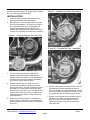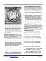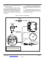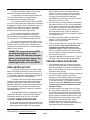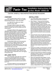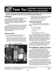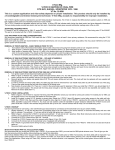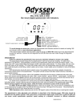
1
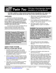
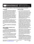
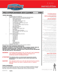
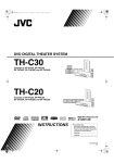
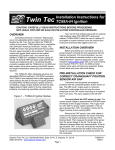
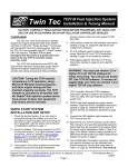
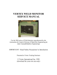
Twin Tec Installation Instructions for Ignition Model 1005 CAUTION: CAREFULLY READ INSTRUCTIONS BEFORE PROCEEDING. NOT LEGAL FOR SALE OR USE IN CALIFORNIA OR ON ANY POLLUTION CONTROLLED VEHICLES. OVERVIEW Twin Tec ignition Model 1005 is intended for use with Harley-Davidson Evolution type motorcycle engines. The Model 1005 replaces the original equipment (OE) electronic ignition system on 1978-99 models. The unit mounts in the gear case cover and uses the standard H-D timing rotor. It can also be used on earlier models with breaker points and mechanical advance. Please note that the 1005S-EX is recommended for 1998 and later Sportster models as it mates directly with the OE wiring harness. The Model 1005 offers adjustable advance, adjustable RPM limit settings in 100 RPM increments, and switch selectable single or dual fire modes. Single fire mode improves starting, reduces the occurrence of backfiring at low RPM, and improves power at high RPM. A red status LED flashes when the engine reaches top dead center (TDC) and allows easy static timing. The status LED also provides diagnostic information. A green VOES LED illuminates when the VOES (vacuum switch) input is active. A special feature allows use of the tachometer wire for a PC link to a laptop computer when the engine is not running. Individual units can be programmed with a custom advance curve and other engine parameters such as rear cylinder timing offset. The use of the tachometer wire for the PC link eliminates the need to remove the outer cover plate. All Model 1005 units log engine operating data that may be downloaded and viewed with our Operating Statistics software. Model 1005 units manufactured starting January, 2006 include a build-in temperature sensor and logging of temperature data. AVOIDING HEAT RELATED FAILURES Heat kills electronics. The Model 1005 uses electronic devices rated for operation at 105 deg C (221 deg F), the highest rating available. The unit can tolerate somewhat higher temperatures, but exposure to temperatures above 125 deg C (257 deg F) will greatly reduce life expectancy. We sometimes see problematic applications where several module failures have occurred. The failure mode is a classic thermal intermittent where the module stops firing one cylinder when it gets hot. We have found that these problematic applications share one or more of the following characteristics: VOES switch removed or non-functional. All street driven engines require vacuum advance. Without vacuum advance at idle and part throttle, thermodynamic efficiency is reduced and engine temperatures increase significantly. Improper carburetor jetting resulting in lean air/fuel ratio (AFR). A lean AFR will cause the engine to run very hot. All performance engine modifications necessitate carburetor rejetting. Carburetors are never correctly jetted out-of-the-box. The only practical means of correctly jetting a carburetor is to test the motorcycle on a chassis dyno equipped with an exhaust gas sniffer or to use our WEGO system. Lack of an oil cooler on a 95 CID or larger engine. Exhaust pipe without heat shield in close proximity to the nose cone. If any of the above applies to your application, the Model 1005 may be exposed to excessive temperatures resulting in reduced life expectancy. Use an infrared thermometer to check the module temperature. Can you also our Operating Statistics software to monitor temperature levels. If excessive temperatures are encountered and cannot be remedied, you should consider using an external module such as our Model 1006 or 1007. INCLUDED AND ADDITIONAL REQUIRED PARTS All units include a parts bag with crimp terminals for coil and VOES hookup and a Packard Weather Pack connector set intended for installation on the tachometer wire to provide an access point for the PC link. FL series Big-Twin models manufactured prior to 1985, FX series Big-Twin and XL Series Sportster models manufactured prior to 1984, all Sportster 1200S models, and all models with original equipment Daytona Twin Tec LLC, 933 Beville Road, Suite 101-H, S. Daytona, FL 32119 (386) 304-0700 www.daytona-twintec.com Page 1 Model 1005 5/2015 breaker points will require H-D timing rotor P/N 3240283 or an equivalent aftermarket part. Figure 2 - Installing Unit (Note Orientation) INSTALLATION 1. Turn off the ignition switch and disconnect the battery ground cable before proceeding. 2. Refer to Figure 1. Remove gear case cover plate and mounting hardware. You may have to drill out two rivets that hold the cover (reassemble with supplied self-threading screws). Remove the sensor plate or breaker points. Make sure that the correct H-D P/N 32402-83 timing rotor is installed. Figure 1 - Feeding Harness Thru Exit Hole Figure 3A - Finished Big-Twin Installation 3. You can completely remove the OE ignition harness and external module (1980 and later models) if desired. However, you must disconnect all OE wires from the coil except the white/black wire from the engine stop/run switch. 4. Install the Model 1005 unit. Wrap one turn of electrical tape around the end of the protective wire harness sleeve. This will compress the sleeve and allow you to easily feed it through the cable exit hole in the gear case cover. The tape will also keep the sleeve end from fraying. You will have to enlarge the hole with a drill on early models and some Sportsters. 5. Rotate the unit and then place it into position as shown in Figure 2. Be careful to avoid damage to the black plastic Hall Effect sensors on the bottom of the unit. 6. Route the wiring harness along the side of the unit and install the mounting standoffs as shown in Figure 3A for Big Twin or 3B for Sportster models. Do not fully tighten the standoffs or install the outer cover plate until after the static timing procedure. 7. Route the wire harness along the frame tubing to the ignition coil. Make sure that the harness is clear of hot exhaust areas and cannot chafe against sharp edges. Secure the harness with nylon cable ties. Daytona Twin Tec LLC, 933 Beville Road, Suite 101-H, S. Daytona, FL 32119 (386) 304-0700 www.daytona-twintec.com Page 2 Model 1005 5/2015 Figure 3B - Finished Sportster Installation CAUTION: Single fire only. Failure to isolate the tach wire from the coil will cause damage to the Twin Tec module that is not covered under warranty. the pink coil wire. Trace the wire going all the way back to the tach to avoid an inadvertent coil connection. 11. Reconnect the battery ground cable. Complete the setup and timing procedures given on pages 3-7. 12. Reinstall the cover plate using two supplied 10-24 x 1/4" socket head screws and lock washers in place of the original rivets. You will have to tap the rivet holes on the inner plate (do this with the plate removed from the bike to avoid damaging the ignition). You can use the supplied 10-24 x 3/8" self threading screw as a tap. 8. Refer to the appropriate wiring diagram. Use the dual fire hookup shown in Figure 4 if you have an OE coil or other coil with two primary terminals. Use the single fire hookup in Figure 5 if you are installing an aftermarket coil with three primary terminals. Use appropriate crimp terminals for coil and VOES hookup. With the exception of the tachometer and rear coil section (single fire only), standard H-D wire color codes are used. Tape up any unused wires. CAUTION: Engine damage from excessive timing advance may result if the purple/white VOES wire is inadvertently shorted to ground. NOTE: The unit is grounded by means of the gear case housing. The mounting surface must not be anodized or painted. OPERATING MODES A single 10 position rotary switch is used to select the operating mode. Switch settings are as follows: 0 Street advance curves, dual fire, multi-spark disabled 1 Street advance curves, dual fire, multi-spark enabled 2 Street advance curves, single fire, multi-spark disabled 3 Street advance curves, single fire, multi-spark enabled 4 Race advance curves, dual fire, multi-spark disabled 9. Install the supplied Weather Pack connector set on the brown tachometer wire as shown. If a tachometer is not used, seal the end of the mating plug with silicone RTV and use it as a protective cover. Use a proper Weather Pack crimping tool or solder the terminals. Pioneer-Standard (www.packard.pios.com) sells Packard crimping tool P/N 12014254. Snap-on sells a low cost tool, P/N PWC30. 10. Single Fire Tach Hookup. If your motorcycle had a tach before installation of the Twin Tec module, the tach was connected to the pink coil wire. When you connect the tach direct to the Twin Tec module as shown in Figure 5 for a single fire application, you must make sure that it is not still connected to 5 Race advance curves, dual fire, multi-spark enabled 6 Race advance curves, single fire, multi-spark disabled 7 Race advance curves, single fire, multi-spark enabled 8 Boot load mode (factory use only - see text) 9 Race advance curves, single fire, kick start (see text) The engine will not run if the mode switch setting does not match the wiring hookup (i.e. you cannot select single fire mode with a dual fire coil hookup). Advance curve families are shown in Figures 6 and 7. Use the street advance curves (mode switch settings 0-3) for stock or mildly modified engines. Use Daytona Twin Tec LLC, 933 Beville Road, Suite 101-H, S. Daytona, FL 32119 (386) 304-0700 www.daytona-twintec.com Page 3 Model 1005 5/2015 the race advance curves (mode switch settings 4-7) for high compression engines. We recommend that you enable multi-spark. When multi-spark is enabled, a continuous series of sparks is fired from the advanced timing point until TDC. Most air-cooled engines require relatively cold spark plugs to prevent detonation under high load. Multi-spark reduces the consequent tendency for plug fouling at idle. Switch setting 8 is a factory reserved setting used for a special "boot load" mode that allows loading an entirely new program into the processor FLASH memory. Switch setting 9 is available on revision 8.3 and later units (revision is labeled on back of unit) and selects race advance curves, single fire, and kick start mode. Multi-spark is disabled. Figure 4 - Dual Fire Wiring Diagram ENGINE STOP/RUN SWITCH WHITE/BLACK TO +12V DUAL FIRE COIL OPTIONAL VOES (VACUUM SWITCH) TO FRONT SPARK PLUG WHITE/BLACK TO REAR SPARK PLUG PURPLE/WHITE PINK TAPE UP WIRE IF VOES NOT USED OPTIONAL TACH ADJUST MODE ADVANCE RPM LIMIT SELECT SLOPE X1000 X100 901 901 78 901 BLUE WIRE USED FOR SINGLE FIRE ONLY - TAPE UP 78 78 901 23 456 23 456 23 456 456 23 RPM 78 STATUS VOES OPTIONAL CABLE CONNECTED TO BROWN TACH WIRE DURING PC LINK TwinTec Internal Ignition Model 1005 BROWN FEMALE TERMINAL MALE TERMINAL WEATHER PACK CONNECTORS TO PC SERIAL PORT MODE SETTINGS FOR DUAL FIRE 0 STREET ADVANCE CURVES, MULTI-SPARK DISABLED 1 STREET ADVANCE CURVES, MULTI-SPARK ENABLED 4 RACE ADVANCE CURVES, MULTI-SPARK DISABLED 5 RACE ADVANCE CURVES, MULTI-SPARK ENABLED Daytona Twin Tec LLC, 933 Beville Road, Suite 101-H, S. Daytona, FL 32119 (386) 304-0700 www.daytona-twintec.com Page 4 Model 1005 5/2015 Figure 5 - Single Fire Wiring Diagram ENGINE STOP/RUN SWITCH TO +12V SINGLE FIRE COIL WHITE/BLACK OPTIONAL VOES (VACUUM SWITCH) TO FRONT SPARK PLUG + _ PINK _ WHITE/BLACK BLUE TO REAR SPARK PLUG PURPLE/WHITE TAPE UP WIRE IF VOES NOT USED OPTIONAL TACH ADJUST MODE ADVANCE RPM LIMIT SELECT SLOPE X1000 X100 901 901 78 78 901 78 78 901 23 456 23 456 23 456 456 23 STATUS WEATHER PACK CONNECTORS FEMALE MALE TERMINAL VOES TwinTec RPM Internal Ignition Model 1005 BROWN MODE SETTINGS FOR SINGLE FIRE 2 STREET ADVANCE CURVES, MULTI-SPARK DISABLED 3 STREET ADVANCE CURVES, MULTI-SPARK ENABLED 6 RACE ADVANCE CURVES, MULTI-SPARK DISABLED 7 RACE ADVANCE CURVES, MULTI-SPARK ENABLED 9 RACE ADVANCE CURVES, KICK START RECOMMENDED TIMING SETTINGS Street and race advance curve families are shown in Figures 6 and 7. Each family has minimum and maximum curves. The advance slope switch allows you to run an advance curve in between these minimum and maximum curves. Advance slope switch setting zero corresponds to the minimum advance curve. Switch setting 9 corresponds to the maximum advance curve. Higher switch settings result in a more aggressive curve. TO PC SERIAL PORT OPTIONAL CABLE CONNECTED TO BROWN TACH WIRE DURING PC LINK Tuning a particular engine setup always requires some trial and error experimentation, but maximum power is usually obtained by using the highest advance setting possible without audible spark knock. Some recommended starting points are given below: For stock engines run on normal pump gas (8789 octane), use the street advance curves and advance slope setting 5. For stock or mildly modified engines run on 92 or higher octane gas, use the street advance curves and advance slope setting 7. Daytona Twin Tec LLC, 933 Beville Road, Suite 101-H, S. Daytona, FL 32119 (386) 304-0700 www.daytona-twintec.com Page 5 Model 1005 5/2015 For high compression engines, use the race advance curves and advance slope setting 2. You can adjust the initial timing by rotating the Twin Tec module relative to the gear housing (clockwise rotation increases initial timing). If you experience spark knock only at low RPM, you can try reducing the initial timing while maintaining an aggressive advance slope for maximum power at high RPM by increasing the advance slope switch setting. If spark knock is a problem at high RPM, decrease the advance slope switch setting. Once you have determined the best switch settings, you can further optimize the timing at a particular RPM by programming a custom advance curve with our PC Link software and optional cable. Note that the wide-open throttle (WOT) curves are active unless the VOES input is grounded. During idle and cruise, the VOES input is grounded (green VOES LED illuminated) and the low manifold pressure (MAP) curves are active. TUNING TIP: Lean air/fuel ratio (AFR) increases the tendency for spark knock. Check AFR and rejet carburetor before optimizing ignition timing. Test the motorcycle on a dyno with an exhaust gas sniffer or use our WEGO. RPM LIMITER SETTING You can set the RPM limit from 3,000 to 9,900 RPM in 100 RPM increments by means of two rotary switches. The RPM limit is X100 switch setting (i.e. 57 = 5,700 RPM). Inadvertent settings below 3,000 RPM are ignored and result in a 3,000 RPM limit. The Model 1005 uses a newly developed RPM limiting algorithm that has been highly optimized for odd firing V twin engines. When the engine is held against the RPM limit, cylinder firing is always paired. This eliminates a torque couple and results in very smooth operation compared to random or sequence type RPM limiters. Set a safe RPM limit that is appropriate for your engine. Most Evolution engines with OE valvetrain components should not be run over 5,700 RPM. STATIC TIMING PROCEDURE 1. Timing marks are located on the flywheel and may be viewed by unscrewing the inspection hole plug. Most engines will have both TDC and advance timing marks for the front cylinder as shown in Figure 8. If you are not sure, refer to your shop manual. You can also identify the TDC mark by removing the spark plugs and rotating the crankshaft (turn rear wheel in high gear) until the front piston comes up on TDC. 2. For static timing, you must rotate the crankshaft so that the front piston is at TDC on the compression stroke. Remove spark plugs and rotate crankshaft. If you place your thumb over the spark plug hole, you will feel pressure as the piston comes up on the compression stroke. Continue rotating the crankshaft until the TDC mark is precisely centered in the inspection hole. 3. Ground the spark plug cables to avoid a shock hazard. You can use small jumper wires with alligator clips for this purpose. 4. Turn on the ignition switch. The red LED is used as a timing indicator. Note that the LED does not immediately illuminate when power is first turned on. Rotate the ignition unit back and forth until the red LED illuminates. Then slowly rotate the unit clockwise until the LED goes out. Note that the LED goes out at TDC. 5. Tighten the standoffs to secure the unit. Turn off the ignition switch and reinstall the spark plugs. PRECISE TIMING PROCEDURE 1. Use a standard timing light. Note that most dialback type timing lights will not work correctly with dual fire applications. If you have a dial-back timing light, set the dial-back to zero. Do not enable multispark while setting timing. 2. The precise timing procedure is based on using the 35 BTDC timing mark and race maximum advance curve with VOES grounded that reaches 35 BTDC around 2,000 RPM (refer to Figure 7). To use this procedure, you must have a VOES switch connected. If a VOES switch is not used, you must ground the purple/white wire while setting the timing. 3. Set mode switch to 4 for dual fire or 6 for single fire. Set advance slope switch to 9. Connect the timing light pickup to the front cylinder spark plug cable. Loosen standoffs securing the ignition unit. Run the engine at a steady speed just over 2,000 RPM. Rotate the ignition to center the 35 BTDC timing mark in the inspection hole. Tighten standoffs and verify that the timing has not changed. When done, change mode and advance slope switches back to desired values. Daytona Twin Tec LLC, 933 Beville Road, Suite 101-H, S. Daytona, FL 32119 (386) 304-0700 www.daytona-twintec.com Page 6 Model 1005 5/2015 Figure 6 - Street Advance Curves 40 35 ADVANCE (DEG) 30 25 20 15 10 MAX ADVANCE AT WIDE OPEN THROTTLE MIN ADVANCE AT WIDE OPEN THROTTLE MAX ADVANCE WITH VOES GROUNDED MIN ADVANCE WITH VOES GROUNDED 5 0 0 1000 2000 3000 4000 5000 6000 7000 ENGINE RPM Figure 7 - Race Advance Curves 40 35 ADVANCE (DEG) 30 25 20 15 10 MAX ADVANCE AT WIDE OPEN THROTTLE MIN ADVANCE AT WIDE OPEN THROTTLE MAX ADVANCE WITH VOES GROUNDED MIN ADVANCE WITH VOES GROUNDED 5 0 0 1000 2000 3000 4000 5000 6000 7000 ENGINE RPM Daytona Twin Tec LLC, 933 Beville Road, Suite 101-H, S. Daytona, FL 32119 (386) 304-0700 www.daytona-twintec.com Page 7 Model 1005 5/2015 Figure 8 - Front Cylinder Timing Marks EARLY STYLE TDC 35° BTDC LATE STYLE TDC 35° BTDC 1996 AND LATER (1995 AND LATER EXPORT) TDC 20° BTDC (NOT USED) GENERAL RECOMMENDATIONS Coil primary resistance must not be less than 3 ohms. Most OE style dual fire and aftermarket single fire coils meet this requirement. Coils for the new Twin Cam 88 engine have low primary resistance and are not compatible. Due to the short lengths involved on motorcycle applications, energy losses in spark plug wires are insignificant. OE carbon core suppression cables will deteriorate after several years. For a more durable replacement, we suggest spiral core spark plug cables. CAUTION: Do not use solid copper spark plug cables or non-resistor type spark plugs. The unit may misfire. The Twin Tec module is compatible with all modern "ground sensing" type tachometers including H-D OE and Autometer units. The red status LED is internally connected to the tachometer output. If the red status LED blinks, the tachometer output should be functional. Some early tachometers require a high voltage trigger pulse. In this case, you will require a commercially available tachometer adapter. VOES CONSIDERATIONS The vacuum switch (VOES) provides the vacuum advance required by all street driven engines. Additional advance under low manifold pressure conditions improves idle stability and fuel economy. Most 1980 and later motorcycles are equipped with a OE VOES. Without vacuum advance at idle and part 35° BTDC throttle, thermodynamic efficiency is reduced and engine temperatures increase significantly. The VOES is normally open. At low manifold pressure (or manifold vacuum greater than about 5 inch-Hg), the VOES grounds the purple/white wire and causes the Twin Tec module to generate additional timing advance. The green VOES LED illuminates whenever the VOES input is active (timing advanced). Refer to the Evo Tech FAQ on our website for more VOES information. The use of a VOES is required for proper operation of the Twin Tec module. If your motorcycle did not include an OE VOES, you can use H-D VOES P/N 26566-91 for stock or mildly modified engines. For high performance engines, we recommend our P/N VOES-KIT-MC7. This is a complete kit with mounting bracket and has a higher vacuum switching level (6-7 inch-Hg) that helps eliminate spark knock under light load or throttle roll-on. PC LINK CABLE AND SOFTWARE The new Twin Tec USB Interface (P/N 18014) provides PC connectivity for all of our engine controls (ignition and fuel injection systems) and eliminates the requirement for multiple cables or a separate USB adapter. Two Windows based programs are available for use with the Model 1005: PC Link Evo for programming custom advance curves and other engine parameters and Operating Statistics for viewing engine operating data. The latest versions of our software are always available for download on our website. The software is free and will work in demo mode without a Daytona Twin Tec LLC, 933 Beville Road, Suite 101-H, S. Daytona, FL 32119 (386) 304-0700 www.daytona-twintec.com Page 8 Model 1005 5/2015 Twin Tec module attached. Refer to the software documentation for details. The brown tachometer wire is used for the PC link. The PC link can access the Twin Tec module when the ignition is turned on and the engine has not yet been started. Once the engine is started, the brown wire resumes its normal function of driving the tachometer. Note that no damage occurs if the engine is inadvertently started while the PC link is still attached. The optional USB interface cable connects to the brown tachometer wire as shown in Figures 4 and 5. The cable also has a ground clip that must be connected to frame or engine ground. The other end of the cable connects to the USB port on a laptop PC. TROUBLESHOOTING FLOWCHART Follow the troubleshooting flowchart shown on the next page. Experience has shown that most units returned for warranty are OK and another problem, such as a defective coil, is later identified. TROUBLESHOOTING TIP: If you are installing an internal (nose cone) ignition for the first time and the engine will not start, the most likely problem is improper static timing. Make sure that the front piston is at TDC on the compression stroke and not on the exhaust stroke. KICK START APPLICATIONS Model 1005 units are preset at the factory with a two revolution cranking delay that is optimum for electric start applications. This cranking delay precludes kick starting. Model 1005 units manufactured starting January, 2006 can be programmed for kick start mode. Twin Tec PC Link Evo software and USB interface cable (P/N 18014) are required to program kick start mode. The mode switch can also be used to select single fire kick start mode on revision 8.3 and higher Model 1005 units (refer to page 3 for details). USE OF VOES INPUT FOR RETARD The Twin Tec module can be programmed to allow alternate usage of the purple/white VOES wire as a retard input. If this feature is enabled, the unit will retard timing up to 10 degrees when the purple/white wire is grounded. This retard feature is useful for turbocharger or nitrous oxide injection applications. Twin Tec PC Link Evo software and USB interface cable (P/N 18014) are required to program the retard feature. Daytona Twin Tec LLC, 933 Beville Road, Suite 101-H, S. Daytona, FL 32119 (386) 304-0700 www.daytona-twintec.com Page 9 Model 1005 5/2015 Troubleshooting Flowchart STARTING POINT DID THE ENGINE RUN PROPERLY BEFORE INSTALLATION OF THE TWIN TEC MODULE? YES NO REPAIR UNDERLYING PROBLEM BEFORE INSTALLING TWIN TEC MODULE. REFER TO MOTORCYCLE SERVICE MANUAL. TURN IGNITION ON. SET ENGINE SWITCH TO RUN. CRANK ENGINE. DOES RED STATUS LED FLASH? NO YES CHECK FOR +12V POWER AT MODULE (WHITE WIRE WITH BLACK STRIPE AT CONNECTOR). IS +12V POWER OK? YES DOES ENGINE START? NO NO YES REPAIR WIRING PROBLEM. REFER TO MOTORCYCLE SERVICE MANUAL. REPLACE TWIN TEC MODULE DOES ENGINE STOP OR DROP CYLINDER AFTER SEVERAL MINUTES OF RUNNING? NO CHECK FOR LOW BATTERY, NO FUEL, OR FOULED SPARK PLUGS. ANY OBVIOUS FAULT FOUND? YES NO CORRECT FAULT REPLACE COIL. IS PROBLEM FIXED? DOES ENGINE MISFIRE UNDER LOAD? NO YES YES NO REPLACE TWIN TEC MODULE DONE CHECK FOR MINIMUM +13V AT COIL+ WITH ENGINE RUNNING AT 2000 RPM. IS VOLTAGE OK? SINGLE FIRE ONLY. INSTALL POWER RELAY KIT. CALL TECH SUPPORT FOR DETAILS. IS PROBLEM FIXED? YES YES YES NO INSTALL POWER RELAY KIT. CALL TECH SUPPORT FOR DETAILS. NO DONE REPLACE SPARK PLUGS, SPARK PLUG WIRES, AND COIL IS PROBLEM FIXED? REPLACE COIL. IS PROBLEM FIXED? YES DONE NO YES NO REPLACE TWIN TEC MODULE DONE REPLACE TWIN TEC MODULE DOES ENGINE MISFIRE AT PART THROTTLE OR WHILE COLD? NO FOR MISC PROBLEMS, CALL TECH SUPPPORT. YES CHECK FOR INCORRECT CARB JETTING OR INTAKE LEAK. IS PROBLEM FIXED? YES DONE Daytona Twin Tec LLC, 933 Beville Road, Suite 101-H, S. Daytona, FL 32119 (386) 304-0700 www.daytona-twintec.com Page 10 NO REPLACE TWIN TEC MODULE Model 1005 5/2015