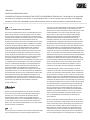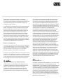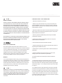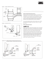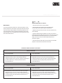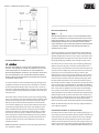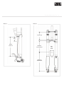
1
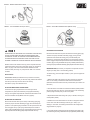
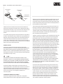
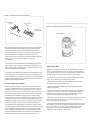
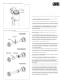
DORADO OWNER’S MANUAL
2009
• ENGLISH
MANITOU SUSPENSION FORKS
CONGRATULATIONS ON CHOOSING THE LATEST IN SUSPENSION TECHNOLOGY. The Dorado is fully assembled
and ready to be installed on your bicycle. It comes equipped with a 1 1/8-inch steerer tube, disc brake mount adapters,
and Hex Lock Thru Axle. A handlebar-mounted reflector must be used for on-road use, which is not included with your fork.
WARNING!
GENERAL CONSUMER SAFETY INFORMATION
BICYCLING IS A HAZARDOUS ACTIVITY THAT REQUIRES THAT THE
RIDER STAY IN CONTROL OF HIS OR HER BICYCLE AT ALL TIMES.
ANY FALL FROM YOUR BICYCLE CAN RESULT IN SERIOUS INJURY
OR EVEN DEATH. READING THIS MANUAL ENTIRELY AND PROPERLY
MAINTAINING YOUR BICYCLE AND SUSPENSION FORK WILL
REDUCE THE POSSIBILITY OF INJURY OR POSSIBLE DEATH. PRIOR
TO EVERY RIDE, YOU SHOULD CLOSELY EXAMINE YOUR SUSPENSION FORK (AFTER CLEANING) IN BRIGHT SUNLIGHT TO ENSURE
THAT NO DAMAGE HAS OCCURRED DURING THE COURSE OF
RIDING, TRANSPORTING OR AFTER A FALL. PAY PARTICULAR
ATTENTION TO THE CROWNS, INNER LEGS, OUTER LEGS, DROPOUTS, BRAKE MOUNT AREAS AND “STRESS POINTS” (SUCH AS
WELDS, SEAMS, HOLES AND POINTS OF CONTACT WITH OTHER
PARTS ETC.) DO NOT RIDE YOUR BICYCLE IF THE FORK SHOWS
ANY SIGNS OF BENDING, LEAKING, CRACKING, CREAKING,
SQUEAKING, CLUNKING OR ANY OTHER UNFAMILIAR NOISES, OR IF
IT IS MISSING ANY OF THE ORIGINALLY SUPPLIED COMPONENTS.
CONTACT YOUR DEALER OR MANITOU CUSTOMER SERVICE AT
888/686-3472 IF YOU HAVE ANY QUESTIONS CONCERNING THE
FUNCTION, INTEGRITY OR CONDITION OF YOUR FORK. ANY
MODIFICATIONS NOT AUTHORIZED IN THIS MANUAL SHOULD BE
CONSIDERED UNSAFE. IF YOU ARE A MODERATE OR AGGRESSIVE
OFF-ROAD RIDER, OR RIDE AT LEAST THREE TIMES A WEEK OVER
ROUGH TERRAIN, MANITOU RECOMMENDS RETURNING YOUR
SUSPENSION FORK TO MANITOU EVERY 2 YEARS FOR A THOROUGH INSPECTION. TAKE YOUR FORK TO A MANITOU AUTHORIZED
DEALER WHO CAN ARRANGE FOR SHIPMENT TO MANITOU.
PHONE: 888/686-3472.
WARNING!
REFLECTORS
MANITOU FORKS ARE DESIGNED FOR OFF-ROAD USE, AND AS
SUCH, THEY DO NOT COME WITH PROPER REFLECTORS FOR
ON-ROAD USE. HAVE YOUR DEALER OR MECHANIC INSTALL
PROPER REFLECTORS TO MEET THE CONSUMER PRODUCT
SAFETY COMMISSION’S (C.P.S.C.) REQUIREMENTS FOR BICYCLES
IF YOUR FORK IS GOING TO BE USED ON PUBLIC ROADS AT ANY
TIME. IF YOU HAVE QUESTIONS REGARDING C.P.S.C. REFLECTORS,
PLEASE CONTACT YOUR DEALER.
WARNING!
IT IS CRITICAL THAT YOU SELECT AND USE THE SUSPENSION FORK
THAT IS APPROPRIATE FOR YOUR ANTICIPATED RIDING STYLE,
THAT YOU USE THE FORK PROPERLY AND FOLLOW THE WARNINGS
CONTAINED IN THE OWNER’S MANUAL, REGARDLESS OF THE
RIDING STYLE. FAILURE TO PROPERLY MATCH THE FORK TO YOUR
FRAME OR RIDING STYLE COULD CAUSE THE FORK TO FAIL,
RESULTING IN A LOSS OF BICYCLE CONTROL AND POSSIBLY
SERIOUS INJURY OR DEATH TO THE RIDER. IN ADDITION, AN
IMPROPER COMBINATION OF FRAME AND FORK FOR THE
INTENDED CATEGORY WILL VOID THE FORK’S WARRANTY. VISIT
OUR WEBSITE AT WWW.MANITOUMTB.COM FOR MORE DETAILED
INFORMATION AND GUIDANCE ON FORK SELECTION FOR YOUR
RIDING STYLE. YOU SHOULD ONLY ATTACH DISC BRAKES AND ANY
OTHER ACESSORIES TO THE DESIGNATED MOUNTING POINTS
PROVIDED ON THE FORKS. NEVER MAKE ANY MODIFICATION TO
YOUR FORK TO ATTACH ANY EQUIPMENT. THERE IS A HEIGHTENED
LEVEL OF VOLUNTARY RISK ASSOCIATED WITH FREERIDING, DIRT
JUMPING AND DOWNHILLING. LARGER STUNTS/JUMPS MEAN MORE
POTENTIAL FOR EQUIPMENT ISSUES OR PROBLEMS AND THE
LIKELIHOOD OF SERIOUS INJURY IS GREATLY INCREASED. LEARN
HOW TO PROPERLY RIDE AROUND OBSTACLES ON THE TRAIL OR
ROAD. HITTING OBSTACLES SUCH AS CURBS, ROCKS, TREES,
ROOTS, HOLES OR SIMILAR OBSTACLES STRAIGHT ON PUTS
FORCES ON YOUR FORK IT WAS NOT DESIGNED TO ABSORB.
LANDING IMPROPERLY AFTER A JUMP OR DROP ALSO PUTS
FORCES ON YOUR FORK IT WAS NOT DESIGNED TO ABSORB. YOU
SHOULD ONLY PERFORM JUMPS OR DROPS WHEN A TRANSITION
OR DOWN RAMP IS AVAILABLE TO HELP YOUR BICYCLE AND FORK
ABSORB THE IMPACT FORCES GENERATED DURING THE LANDING,
AND BOTH WHEELS SHOULD SMOOTHLY MAKE CONTACT WITH THE
TRANSITION OR DOWN RAMP AT THE SAME TIME. ANY OTHER TYPE
OF LANDING IS DANGEROUS, AS IT COULD OVERLOAD THE FRAME
OR FORK AND RESULT IN A COMPONENT PART FAILURE AND AN
ACCIDENT OR COULD CAUSE YOU TO LOOSE CONTROL OF THE
BICYCLE, EVEN WITHOUT A COMPONENT PART FAILURE. THE
STEEPNESS AND LENGTH OF THE TRANSITION OR DOWN RAMP
DEPENDS ON THE HEIGHT FROM WHICH YOU JUMP OR DROP.
EVERY SITUATION IS DIFFERENT FOR EVERY RIDER; CONSULT
WITH AN EXPERIENCED RIDER BEFORE ATTEMPTING ANY
JUMP OR DROP.
FAILURE TO PROPERLY RIDE AROUND OBSTACLES ON THE TRAIL,
OR FAILURE TO PROPERLY LAND AFTER A JUMP OR DROP COULD
CAUSE YOUR FORKS TO FAIL, RESULTING IN A LOSS OF BICYCLE
CONTROL AND, POSSIBLY, SERIOUS INJURY OR DEATH TO THE
RIDER. RIDE ONLY IN AREAS SPECIFICALLY DESIGNATED FOR
YOUR RIDING STYLE. DO NOT MISUSE OR ABUSE YOUR FORKS.
LEARN HOW TO RIDE, AND ALWAYS RIDE WITHIN YOUR ABILITIES.
OUT-OF-CONTROL RIDING PUTS THE EQUIVALENT OF YEARS OF
DORADO OWNER’S MANUAL ‘09
HARD USE ON YOUR FORKS AFTER ONLY A FEW RIDES.
SOMETIMES THE DAMAGE IS NOT OBVIOUS TO THE USER, BUT
COULD HAVE FAILED INTERNAL COMPONENTS OR DAMAGED THE
LOAD CARRYING ABILITIES OF THE MATERIALS USED IN THE
CONSTRUCTION OF THE FORK.
ALL SUSPENSION FORKS REQUIRE REGULAR MAINTENANCE AND
REPAIR. THE HARDER YOU RIDE, THE MORE OFTEN YOU MUST
INSPECT AND MAINTAIN YOUR FORK. IF YOUR FORK STARTS
MAKING ANY STRANGE NOISES, CLUNKS, CREAKS, CLICKS, OR
FEEL “LOOSE” OR DIFFERENT IN ANY WAY, IT SHOULD NOT
CONTINUE BEING USED, BUT IMMEDIATELY HAVE A CERTIFIED
MANITOU SERVICE CENTER INSPECT AND REPAIR THE FORK
BEFORE YOU RIDE AGAIN. INSPECT YOUR FORK REGULARLY TO
SEE THAT IT IS NOT BENT, DEFORMED, CRACKED, OR CHIPPED.
IF ANY OF THESE CONDITIONS EXIST THE FORK SHOULD NOT BE
USED. A CERTIFIED MANITOU SERVICE CENTER SHOULD INSPECT
AND REPAIR THE FORK BEFORE IT IS USED AGAIN.
IDENTIFY YOUR RIDING STYLE
It is critical that you select and use the suspension fork that is appropriate
for your anticipated riding style, that you use the fork properly, and that you
follow all warnings contained in this owner’s manual regardless of riding
style. Visit our website at www.manitoumtb.com for more detailed
information and guidance on fork selection for your riding style.
The Dorado is a downhill-specific suspension fork. This discipline is only for
professional or highly-skilled riders. It includes use on relatively high jumps
(or “drops”) and negotiating larger obstacles such as boulders, fallen trees
or holes. These forks should be used only with disc brakes, as well as frames,
wheels and other components specifically designed for this riding style.
WARNING!
“DOWNHILL”, “FREESTYLE” OR COMPETITIVE RIDING
TO RIDE DOWNHILL AT HIGH SPEED OR IN COMPETITION IS TO
VOLUNTARILY ASSUME A VERY HIGH RISK, AND DOWNHILL OR
FREESTYLE RIDING CAN LEAD TO SERIOUS ACCIDENTS.
“DOWNHILLING” SPEEDS CAN APPROACH THOSE SEEN ON
MOTORCYCLES WITH SIMILAR HAZARDS AND RISKS. WEAR
APPROPRIATE SAFETY GEAR, INCLUDING A FULL-FACE HELMET,
3
FULL- FINGER GLOVES AND BODY ARMOR. HAVE YOUR BICYCLE
INSPECTED BY A QUALIFIED MECHANIC BEFORE EVERY EVENT,
AND BE SURE IT IS IN PERFECT WORKING CONDITION. ROUTINE
AND THOROUGH MAINTENANCE IS EVEN MORE CRITICAL THAN
WITH A BIKE NOT USED FOR DOWNHILLING OR FREESTYLE RIDING.
CONSULT WITH EXPERT RIDERS AND RACE OFFICIALS ON CONDITIONS AND EQUIPMENT ADVISABLE AT THE SITE WHERE YOU PLAN
TO RIDE DOWNHILL OR FREESTYLE. SUSPENSION AND
DISC BRAKES MAY INCREASE THE HANDLING CAPABILITIES AND
COMFORT OF YOUR BICYCLE AND MAY ALLOW YOU TO RIDE
FASTER, BUT DO NOT CONFUSE THE ENHANCED CAPABILITIES OF
A SUSPENSION BIKE WITH DISC BRAKES WITH YOUR OWN CAPABILITIES. INCREASING YOUR SKILL WILL TAKE TIME AND PRACTICE.
PROCEED CAREFULLY UNTIL YOU ARE SURE YOU ARE COMPETENT
TO HANDLE THE FULL CAPABILITIES OF YOUR BIKE. WHILE THE
RUGGED APPEARANCE OF MOUNTAIN BIKES AND DISC BRAKES
MIGHT SUGGEST THEY ARE INDESTRUCTIBLE, THEY ARE NOT.
CERTAINLY THEY ARE TOUGH AND STURDY. DOWNHILL OR
FREESTYLE RIDING OR RACING PLACES EXTREME STRESS ON
BICYCLES AND THEIR COMPONENTS (LIKE IT DOES RIDERS).
REPEATED USE OF A FORK IN DOWNHILL RIDING MAY RESULT IN
SUDDEN OR PREMATURE FAILURE OF A BICYCLE OR COMPONENT
RESULTING IN SEVERE INJURIES. IF YOU PARTICIPATE IN THESE
TYPES OF EVENTS, THE LIFETIME OF THE PRODUCT MAY BE
SIGNIFICANTLY SHORTENED DEPENDING UPON THE LEVEL AND
AMOUNT OF RACING. THE “NORMAL WEAR” OF A COMPONENT MAY
DIFFER GREATLY BETWEEN COMPETITIVE AND NON-COMPETITIVE
USES, WHICH IS WHY PROFESSIONAL LEVEL RIDERS OFTEN USE
NEW BIKES AND COMPONENTS EACH SEASON AS WELL AS HAVE
THEIR BIKES SERVICED BY PROFESSIONAL MECHANICS.
WARNING!
REDUCED FORK LIFE
THE LIFE OF THIS FORK WILL BE REDUCED IF (1) YOU USE IT MORE
THAN THE AVERAGE USER, (2) YOU ARE HEAVIER THAN THE
AVERAGE RIDER, (3) THE TERRAIN YOU RIDE ON IS ROUGHER THAN
AVERAGE, (4) YOU TEND TO BE HARDER ON COMPONENTS THAN
THE AVERAGE RIDER, (5) IT IS INSTALLED OR MAINTAINED IMPROPERLY, (6) IT MUST ENDURE MORE ADVERSE ENVIRONMENTAL
CONDITIONS THAN THE AVERAGE FORK (I.E. SWEAT, CORROSIVE
MUD, SALTY BEACH AIR ETC.), AND/OR (7) YOU DAMAGE IT IN A
CRASH, JUMP, OR THROUGH OTHER ABUSE. THE MORE FACTORS
YOU MEET, THE MORE ITS LIFE WILL BE REDUCED; HOWEVER IT IS
IMPOSSIBLE TO SAY HOW MUCH.
DORADO OWNER’S MANUAL ‘09
WARNING!
PRESS FIT CROWNS
PRESS FIT CROWNS THE STEERER TUBE AND STANCHION DROPOUTS ARE PRESS FIT AT THE FACTORY AND SHOULD NEVER BE
REMOVED FROM THE CROWN OR DROPOUTS RESPECTIVELY.
PRESSING THEM OUT WILL PERMANENTLY DAMAGE THE CROWN
BEYOND REPAIR AND RENDER IT UNSAFE FOR ANY CONTINUED
USE. NEVER ATTEMPT TO THREAD A THREADLESS STEERER TUBE.
CUTTING THREADS WILL WEAKEN THE STEERER TUBE AND CAUSE
AN UNSAFE CONDITION. OBTAIN THE CORRECT CROWN/STEERER
FROM YOUR DEALER, OR CONTACT MANITOU CUSTOMER SERVICE
AT 888/686-3472.
REPLACEMENT OF THE ENTIRE CROWN/STEERER ASSEMBLY MUST
BE DONE TO INCREASE STEERER TUBE LENGTH. REMOVING AND
REPLACING THE STEERER TUBE WILL RESULT IN AN UNSAFE
CONDITION AND SHOULD NEVER BE DONE.
CAUTION!
INSTALLATION INSTRUCTIONS
Ensure that the proper steerer tube has been delivered on your fork.
The steerer tube may need to be cut to length to fit your bicycle’s head tube.
If you are not familiar with this procedure, or do not have the proper tools to
cut the steerer tube, it is recommended that you seek a dealer with a
qualified bicycle mechanic to perform the installation. When cutting a
steerer tube of a fork, make sure to measure twice before cutting; forks cut
too short during installation are NOT covered by the warranty.
BREAK-IN
Your new fork is designed to break in during your first few rides (about 20
hours total riding time). Prior to break-in, you may notice your fork feels tight
and slightly notchy. Following the break-in period, your fork will feel much
smoother and will react to bumps much better than when you first put it on
your bike. After 20 hours, you may want to recheck adjustments (where
applicable) to fine-tune the fork completely.
WARNING!
WHENEVER YOU INSTALL ANY NEW COMPONENT ON YOUR BIKE,
MAKE SURE YOU THOROUGHLY TRY IT OUT CLOSE TO HOME (WITH
YOUR HELMET) WHERE THERE ARE NO OBSTACLES, TRAFFIC OR
OVERLY CHALLENGING TERRAIN. MAKE SURE EVERYTHING IS
WORKING PROPERLY BEFORE GOING OFF ON A RIDE OR
TO A RACE.
4
FORK INSTALLATION – DUAL CROWN FORKS
1. Remove the old fork from your bicycle.
2. Measure and cut the steerer tube to fit your bicycle’s head tube (see
previous WARNING). You can use your old fork as a guide for cutting the
steerer tube length. To determine which upper triple clamp your frame will
need see Table 5 on page 12.
3. Remove the headset crown race from the old fork and press onto the fork
steerer until the race is seated snugly against the top of the crown per the
headset manufacturer’s instructions.
4. Clean and grease the headset bearings and races per the headset
manufacturer’s instructions.
5. Install the lower bearings (if applicable) on fork crown race per the
headset manufacturer’s instructions.
6. Insert the steerer tube into the head tube of the frame.
7. Install the upper bearings, stem spacers, upper triple clamp and stem or
integrated upper handlebar stem clamp.
8. Install the stem cap and bolt. Tighten the bolt to headset manufacturer’s
specifications.
9. Install the handlebars and torque the stem pinch screws or stem
clamping system to stem manufacturer’s specifications.
10. Install the brake levers and adjust per the brake manufacturer’s
instructions.
11. Adjust stanchion legs in the upper and lower crowns. The top of the
lower clamp must be between 10mm-15mm below the top of the gold
sleeve and should be even. Both right and left outer carbon legs should be
set at the same height +/- 1mm. Torque pinch bolts to specs found in Table
6 on Page 12.
12. To install the hex axle, simply slip the axle into the dropout, small axle
hex side first into the large dropout hex. Thread the set bolt into the small
hex side and snug slightly. Push the fork up and down a few times to center
the axle and hub and then tighten all pinch bolts to recommendations found
in Table 6. NOTE: The Dorado may only use a 110mm wide hub. All other
hub sizes are unsafe and will cause the fork to fail and may lead to potential
injury of rider. (See Image 2 on page 5.)
IMAGE 1 - LOWER CROWN INSTALLATION
Lower
Sleeve
DORADO OWNER’S MANUAL ‘09
5
10-15mm
[0.39-0.59in]
BRAKE CALIPER ADAPTER INSTALLATION
Both post mount and IS disc brake caliper adapters are included with your
fork (HBG P/N 141-23817). Identify the mounting standard of your disc
brake caliper. Post mount calipers have bolt holes parallel to the orientation
of the rotor. IS calipers have bolt holes perpendicular to the orientation of
the rotor. Consult your brake manufacturer’s owner’s manual for further
information. Only a 203mm [8in] rotor may be used on the Dorado.
Lower
Crown
Once the proper adapter is identified, install the adapter as shown. Use the
two bolts provided in the kit (M6x1, 20mm long), Torque to 9.0-11.3 N-M
[80-100 lb-in].
IMAGE 2 - AXLE INSTALLATION
BRAKE CABLE INSTALLATION
WARNING!
FAILURE TO PROPERLY ROUTE AND SECURELY ATTACH THE FRONT
BRAKE CABLE TO THE FORK CAN CAUSE SERIOUS INJURY OR DEATH.
Included with your fork is a small, black disc brake cable guide that can be
attached to the lower crown to aid in routing the cables to disc brake
calipers. Also included is a standard zip tie to secure the cable to the bash
guard. The preferred method is to route the cable so that it runs inside the
spring leg, secured to the bash guard, then through the brake cable guide.
The cable should be loose through the lower crown cable guide so the
cable is free to translate up and down. Make sure the brake line is not
crimped and does not touch the tire as the fork moves through its
range of travel. (See Image 5 on page 6)
Hex Axle
Hex Pinch
Set Bolt
IMAGES 3 & 4 - IS MOUNT BRAKE CALIPER ADAPTER INSTALLATION
POST-MOUNT BRAKE CALIPER ADAPTER INSTALLATION
068077
Post Mount Adapter
068078
IS Mount Adapter
2x 064535
4mm Hex
Torque to:
9.0-11.3 N-M
(80-100 lb-in)
2x 064535
4mm Hex
Torque to:
9.0-11.3 N-M
(80-100 lb-in)
Drop-out Boss
Spring (Left) Leg
Drop-out Boss
Spring (Left) Leg
IMAGE 5 - BRAKE CABLE INSTALLATION
DORADO OWNER’S MANUAL ‘09
IMAGE 6 - TOP SCHRADER VALVE (FILL ONLY)
6
IMAGE 7 - BOTTOM SCHRADER VALVE (RELIEF ONLY)
WARNING!
DECREASING AIR PRESSURE
WHEN INSTALLING THE WHEEL WITH A PROPERLY INFLATED TIRE,
CHECK TO MAKE SURE THE FORK ACHIEVES MINIMUM TIRE
CLEARANCE. FAILURE TO CONFORM TO RECOMMENDED TIRE
CLEARANCE SPECIFICATIONS MAY CAUSE THE TIRE TO STOP
SUDDENLY DURING USE CAUSING PERSONAL INJURY OR DEATH.
Remove the Schrader valve cap from the bottom of the left leg (spring leg).
Thread on the pump’s Schrader valve fitting snuggly. Turning the fork
upside down will minimize oil entering pump. If the fork already has
pressure in it, the pressure gauge will read a non-zero pressure when the
valve is engaged. Depress the pressure bleed valve until desired pressure
is read on gauge. If using a traditional shock pump, minimize pressure loss by
removing the pump’s Schrader valve fitting quickly. Replace Schrader valve cap.
Measure minimum tire clearance from any point on the profile of the tire
upward to the bottom of the crown (see Image 15 page 13). Compare to
Table 1 on page 12 for minimum tire clearance. Measure the tire at
maximum width (see Image 15). Compare with Table 1 for maximum
tire width.
INITIAL SET-UP
MEASURING SAG (The amount your suspension compresses due to the
weight of your body when in a natural riding position)
To measure sag, you’ll need a tape measure, a pencil, a piece of paper and
a helper.
MEASURING TRAVEL (the total amount of up and down movement)
To determine how much travel your fork has, simply measure the distance
from the top of the droup-out to the seal on the outer leg.
See Table 2 on page 12 to determine travel.
ADJUSTING MAIN SPRING AIR PRESSURE
The Dorado’s air spring is performance tuned to be high-volume,
low-pressure for quick, linear break-away and progressive bottoming
ramp-up. The negative and positive air chambers are linked with a check
valve; the chambers auto-equilibrate when set-up properly.
1. Measure the distance (M) from the top of the dropout to the dust seal
when no one is sitting on the bike and write down this measurement.
(Remember the exact locations of the two points because you’ll need to use
them later.)
2. Have the rider sit on the bike and measure the distance (SAG1) between
the same two points as in step one. It is important to be in the normal riding
position (weight centered) with your feet on the pedals.
3. Repeat measurement after having rider “jump” on the bike, returning to a
neutral position (SAG2).
INCREASING AIR PRESSURE
Remove the Schrader valve cap from the top of the left leg (spring leg).
Thread on pump’s Schrader valve fitting snuggly. If the fork already has
pressure in it, the pressure gauge will read a non-zero pressure when the
valve is engaged. Pump up air spring until desired pressure is read on
gauge. If using a traditional shock pump, minimize pressure loss by removing
the pump’s Schrader valve fitting quickly. Replace Schrader valve cap.
4. Subtract the second measurement from the first “un-weighted” measurement in each case. Take the average of the two. [(M – SAG1) + (M –
SAG2)] / 2 = AVG SAG. The resulting measurement is the average static
sag (see Table 3 on page 12).
5. To increase air spring pressure remove the Schrader air cap located on the
top of the left leg and, using a dedicated shock pump (Manitou part #85-4162),
IMAGE 8 - HIGH SPEED, SHORT TRAVEL IMPACT
Bicycle Direction
of Travel
Bicycle Direction
of Travel
Unsprung Mass/
Wheel Movement
Rock/Root,
etc.
Rock/Root,
etc.
inflate the fork with the desired pressure. Be aware that sometimes air
systems lose a small amount of pressure when a standard shock pump is
removed from the valve stem, so you may want to check exactly how much
your pump loses by reinstalling it after you have set and checked the
pressure.
6. To decrease air spring pressure remove the Schrader air cap located on
the bottom of the left leg and using a dedicated shock pump (Manitou part
#85-4162), depress the pressure bleed valve until the desired pressure is
reached. Be aware that sometimes air systems lose a small amount of
pressure when a standard shock pump is removed from the valve stem, so
you may want to check exactly how much your pump loses by reinstalling it
after you have set and checked the pressure.
DAMPING SYSTEM
The Dorado is equipped with the following Damping technologies:
Externally Adjustable TPC+ Compression Damping, Externally Adjustable
High Speed Compression Damping, Integrated Hydraulic Bottom-Out
Resistance Circuit, and Externally Adjustable Rebound Damping. All these
technologies are contained in an open-bath cartridge, making it lightweight,
quick to bleed, and easy to set-up.
WARNING!
THE DAMPING SYSTEM IS AN OPEN BATH SYSTEM. OIL MAY
INTERNALLY LEACH OUT OF THE DAMPING CARTRIDGE DURING
SHIPPING OR IF YOUR BIKE IS STORED UPSIDE-DOWN. THE FORK
SHOULD BE BLED PRIOR TO USE IF THE FORK IS NOT STORED
UPRIGHT. FAILURE TO DO SO MAY RESULT IN POOR PERFORMANCE.
To bleed the cartridge, hold fork upright or as mounted on bike. Turn
rebound adjuster knob to “Full Closed” Position. Stroke fork 10-20 times or
until rebound speed is slow throughout travel of fork. Reset rebound
adjuster knob to desired setting. The bleed process may be supplemented
by also turning the TPC+/ red compression adjusted to the
“full closed” position.
COMPRESSION DAMPING ADJUSTMENT
The Dorado is equipped with both an external “TPC+ Compression”
damping adjustment and an external “High Speed Compression” damping
DORADO OWNER’S MANUAL ‘09
7
adjustment, as well as a dedicated independent hydraulic bottom-out circuit.
These damping technologies allow greater adjustability for specific events
encountered on terrain; this allows the fork to be plush during stutter bumps
and firm during bottoming while giving the rider the necessary adjustment to
tune the Dorado to any riding conditions.
There are three distinct damping stages through the travel of the fork. The
first stage, 0-100mm [0-4in] of travel, is dedicated to high-speed unsprung
wheel movement and low speed rider trail movement. The second stage,
100-160mm [4-6in] of travel is dedicated to high-speed sprung weight
movement of the rider and bike. The third stage, 160-203mm [6-8in] of
travel, is dedicated to bottoming resistance.
Typically, a “high speed” compression event is characterized by a high shaft
velocity incident caused by either the unsprung wheel mass being forced
towards bike chassis or the sprung rider mass being forced towards the
ground. In the first case the high shaft velocity is caused by the bike, at high
speeds, coming in contact with a small obstacle (less than 100mm [4in]; i.e.
stutter bumps, rocks, and roots). See figure below. Generally, it is desirable
for the fork to be plush (minimal damping force) when encountering a high
speed event of this nature and should travel through the stroke with minimal
movement translated to the rider. This damping characteristic is set by
High-Speed Adjuster. The High-Speed Adjuster is located on the bottom of
the right dropout. It is black and encircles the red TPC+ adjuster. The
High-Speed Adjuster, when turned clockwise (counter-clockwise when
reference from the handlebars), will make the suspension firmer during
short–travel, high-speed events. Turning the High-Speed Adjuster
counter-clockwise (clockwise when reference from the handlebars) will
make the suspension plusher during high-speed events. The High-Speed
Adjuster is equipped with 18 detent positions. NOTE: WHEN THE
HIGH-SPEED ADJUSTER (OUTER KNOB) IS TURNED, THE TPC+
ADJUSTER (INNER KNOB) WILL FOLLOW. THIS WILL NOT CHANGE
THE SETTING OF THE TPC+ ADJUSTER. THE TPC+ ADJUSTER
SETTING WILL ONLY CHANGE IF TURNED INDEPENDENTLY OF THE
HIGH-SPEED ADJUSTER.
In the second case of high-speed shaft velocity, gravity forces the rider’s
mass downward, deep into the fork’s travel (more than 100mm [4in]) from
landing a jump or a drop. See figure below. This damping characteristic is
set by the TPC+ Adjuster. The TPC+ Adjuster is located on the bottom of
the right dropout. It is red and is encircled by the black High-Speed Adjuster.
The TPC+ Adjuster, when turned clockwise (counter-clockwise when
reference from the handlebars) will make the suspension firmer during
high-speed, deep-travel events. Turning the TPC+ adjuster counterclockwise (counter-clockwise when reference from the handlebars) will
make the suspension plusher during high-speed, deep-travel events. The
TPC+ Adjuster is equipped with 18 detent positions.
IMAGE 9 - HIGH SPEED, DEEP TRAVEL IMPACT
Bicycle Direction
of Travel
DORADO OWNER’S MANUAL ‘09
8
Bicycle Direction
of Travel
IMAGE 10 - REBOUND DAMPING ADJUSTMENT
Sprung Mass/
Chassis Movement
Rebound Adjuster
During extreme High-Speed events, the rider’s mass forces the fork deep
into its travel (more than 160mm [6in]). During these severe bottoming
events the damper will engage the Hydraulic Bottom-Out Resistance
Circuit. This dedicated circuit creates a cushion that is both position- and
shaft-velocity-dependent; the faster and deeper the fork enters the
Hydraulic Bottom-Out, the more force it generates to prevent the fork from
bottoming. The Hydraulic Bottom-Out is factory tuned, and is
non-adjustable.
A “Low-Speed” event is characterized by a short-travel (less than 100mm
[4in]) low-shaft-velocity as a result of changes to the bike’s trail stance (i.e.
berms, G-outs, pedaling, & braking). The low-speed characteristics of the
fork will be dictated by the TPC+ adjuster.
It is the rider’s responsibility to ensure their fork is tuned properly to account
for rider weight, spring rate, tire pressure, terrain style, and riding style. It is
recommended that the fork is tested on “easy” terrain in various High-Speed
Adjuster and TPC+ Adjuster settings to both feel the range of adjustment
and find the ideal setting for the course.
REBOUND DAMPING ADJUSTMENT
Rebound damping controls the speed at which the fork returns to the
un-sprung or sagged position. During a high-speed, short-travel event it is
desirable to have the fork return to un-sprung position quickly to prevent
“pack-up”. “Pack-up” is when the fork does not return fast enough through a
series of stutter bumps and the fork becomes low in the travel, minimizing
the available travel for additional high speed events. Contrarily, during
high-speed, deep-travel events it is desirable to have the fork return to the
un-sprung state more slowly to prevent loss of traction after the event. It is
the rider’s responsibility to ensure their fork is tuned properly to account for
rider weight, spring rate, tire pressure, terrain style, and riding style. It is
recommended that the fork be tested on “easy” terrain in various rebound
settings to both feel the range of adjustment and find the ideal setting for the
course. The Rebound Adjuster is located on top of the right leg. It is blue
and is equipped with 18 detent positions. Turning the Rebound Adjuster
clockwise will make the suspension return slower. Turning the Rebound
Adjuster counter-clockwise will make the suspension return faster.
TRAVEL ADJUSTMENT
The Dorado is capable of being internally adjusted from 203mm of travel to
180mm of travel. This may be done with no change to the spring rate for a
given spring air pressure. The comp-rod assembly must be removed for this
operation. If the fork is not yet installed on the bike, skip to step four.
1. Loosen the four drop-out pinch bolts (two per dropout) using a 4mm hex
wrench; do not remove the pinch bolts from the dropouts.
2. Remove the Hex Axle bolt using a 6mm hex wrench. Slide the 20mm
Hex Axle out of the drop-outs and wheel hub.
3. Remove brake caliper completely from left dropout, along with brake
cable from left leg guard.
4. Remove the Schrader valve cap beneath the left dropout. Relieve all air
pressure from the positive air valve using a shock pump with a pressure
relief valve and pressure gauge. The pressure gauge should read 0 PSI
before removing the pump. Replace the Schrader valve cap.
5. Remove the Schrader valve cap on top of the left leg (spring leg). Using a
36mm wrench loosen (but do not remove) the grey topcap on the gold
sleeve on top of the left leg (spring leg).
6. It is recommended that the left leg (spring leg) be completely removed for
this operation. Loosen the two pinch bolts on the left side (spring side) of the
lower crown, and the one pinch bolt on the left side (spring side) of the
upper crown using a 5mm hex wrench. Slide the left leg (spring leg)
completely out from the upper and lower crowns.
IMAGE 11 - COMPRESSION DAMPING ADJUSTMENTS
Low Speed
Adjuster
High Speed
Adjuster
DORADO OWNER’S MANUAL ‘09
9
7. Holding the leg upright, continue to remove the top cap from the sleeve
on top of the leg. Slide the outer carbon leg down.
8. Using a 13mm open wrench hold the flats on the comp rod adapter (it may
be necessary to slide the bottom-out spacer down to gain access) and remove
the top cap with a 36mm wrench. Do this over an oil pan, as some oil may spill.
9. Turning the leg upside down, allow the Splash-Bath oil to drain into an oil
pan. DO NOT REUSE OIL; DISCARD PROPERLY WITH LOCAL OIL
RECYCLER. When all oil has drained, remove the outer leg by sliding it
away from the dropout.
IMAGE 12 - TRAVEL ADJUSTMENT
Top-Out Seated in
203mm Position
Top-Out Screw
[20mm]
Top-Out Nut
[16mm]
10. Using a 20mm open-end wrench, loosen the comp-rod end cap and
remove the comp-rod assembly form the leg. Do this over an oil pan, as
some oil may spill.
11. Locate the top-out nut (gold) and screw (black) on the comp-rod.
Loosen and unthread the nut from the screw, then slide apart to reveal the
retaining ring. Splay the retaining ring to remove from grove and move to
groove corresponding to the desired travel position; 203mm is the position
closest to the air piston, 180mm is the position closest to the end cap.
Rethread the top-out screw and bolt over the retaining ring, torque to 3.4
N-M [30 IN-LB]. (See ‘Travel Adjustment’ Image)
12. Coat the air piston with Splash Bath (HBG P/N 85-0023). Insert the air
piston into the leg being sure to minimize contact between the threads and
o-ring. Pour an additional 5cc of Splash Bath on top of the inserted piston.
Using a 20mm crow’s foot torque wrench tighten the comp rod end cap to
6.8-9.0 N-M [60-80 LB-IN].
Top-Out Disassembled
for Travel Adjustment
Retaining Ring
203mm Position
Retaining Ring
180mm Position
13. Slide the outer carbon leg back onto the inner leg. Using a 13mm open
wrench hold the flats on the comp rod adapter. Tighten the top cap with a
36mm torque wrench to 1.7-2.8 N-M [15-25 LB-IN]. Pour 30cc Splash Bath
(HBG P/N 85-0023) into outer spring leg.
14. With the leg fully extended, thread the top cap into the spring leg, hand
tight, being sure the o-ring is engaged.
Top-Out Seated in
180mm Position
15. Slide the left leg (spring leg) completely into the upper and lower
crowns. The top of the upper crown must be within 10-15mm below of the
top of the tapered gold sleeve. Tighten the two pinch bolts left side (spring
side) on the lower crown, and the one pinch bolt on the left side (spring
side) on the upper crown using a 5mm hex torque wrench to 10.7-12.4 N-M
[95-110 LB-IN].
16. Using a 36mm wrench, tighten the grey top cap to 8-9.0 N-M [60-80 LB-IN].
17. Fill only the upper Schrader valve with desired air pressure. Manitou
recommends using a pump equipped with a 2-stage valve relief system to
prevent any pressure loss when disconnecting the pump from the valve
stem. Recommended air pressure is 50 – 90 PSI. Replace the Schrader cap.
18. Remount the wheel and Hex Axle and brake caliper per manufacturer’s
specifications. First tighten the hex Axle to 3.4-4.5 N-M [30-40 IN-LB] using
a 6mm hex torque wrench. Then tighten all four pinch bolts to 3.4-4.5 N-M
[30-40 IN-LB] using a 4mm hex torque wrench.
DORADO OWNER’S MANUAL ‘09
10
WARNING!
BEFORE EVERY RIDE YOU SHOULD:
MAINTENANCE
1. Ensure that the Hex Axle is properly installed.
Your fork requires periodic maintenance, cleaning and inspection. This is
because moisture and contamination may build up inside the fork depending on the severity of riding conditions. To maintain top performance, it is
recommended that the fork be periodically disassembled, cleaned, dried
and re-lubricated. You can download service and tuning instructions on the
web at www.manitoumtb.com
2. Ensure that all bolts are tightened to the appropriate torque
recommendations by the parts’ respective manufacturers.
3. Wipe the inner legs and clean the fork. Check the entire fork for any
obvious damage.
4. Check the headset for proper adjustment. To check for a loose front
headset apply the front brake with both wheels on level pavement and push
the bike forwards and backwards rapidly to see if you hear the headset
rattling. If it is then it is too loose. Follow headset manufacturer’s
instructions to tighten.
5. Ensure that the front brake cable is properly routed and check brake
adjustment. Follow brake manufacturer’s instructions.
SUGGESTED SERVICE INTERVALS FOR DORADO
NORMAL CONDITIONS
Short, Infrequent Rides
Long, Frequent Rides
Disassemble fork per Service Manual. Clean outer leg and replace
Splash Bath oil every 6 months. Service damping systems by
changing the damper oil every six months. Check the oil level sitting on
top of the air piston every 12 months per directions found on
www.manitoumtb.com.
Disassemble fork per Service Manual. Clean outer leg and replace
Splash Bath oil every four months. Service damping systems by
changing the damper oil every four months. Check the oil level sitting
on top of the air piston every eight weeks per directions found on
www.manitoumtb.com.
SEVERE CONDITIONS
Short, Infrequent Rides
Long, Frequent Rides
Disassemble fork per Service Manual. Clean outer leg and replace
Splash Bath oil every four months. Service damping systems by
changing the damper oil every four months. Check the oil level sitting
on top of the air piston every eight weeks per directions found on
www.manitoumtb.com.
Disassemble fork per Service Manual. Clean outer leg and replace
Splash Bath oil every three months. Service damping systems by
changing the damper oil every three months. Check the oil level sitting
on top of the air piston every six weeks per directions found on
www.manitoumtb.com.
IMAGE 13 - DAMPING OIL HEIGHT CHECK
Outer Leg
Top Cap
DORADO OWNER’S MANUAL ‘09
106-114mm
[4.2-4.4in]
11
REPLACING DAMPING OIL
WARNING!
Oil Level
Inner Leg
Top Cap
CHECKING DAMPING OIL LEVEL
WARNING!
SETTING THE PROPER OIL LEVEL IN YOUR SUSPENSION FORK IS
CRITICAL. THE DAMPING IS LOCATED IN THE RIGHT LEG OF YOUR
FORK. INSUFFICIENT OIL VOLUME WILL ALLOW FOAMING AND
REDUCE PERFORMANCE. EXCESS OIL WILL RESTRICT TRAVEL AND
MAY CAUSE DAMAGE TO THE SYSTEM AND CREATE AN UNSAFE
RIDING CONDITION. FINISH READING THIS ENTIRE SECTION PRIOR
TO ALTERING THE OIL LEVEL.
To check the oil level it is recommended that the right leg (damping leg) be
completely removed from the rest of the fork for this operation. Loosen the
two pinch bolts right side (damping side) on the lower crown, and the one
pinch bolt on the right side (damping side) on the upper crown using a 5mm
hex wrench. Slide the right leg (damping leg) completely out from the upper
and lower crowns.
Use a 36mm wrench to remove the top cap on the right outer leg (damping
leg). It is not necessary to remove the rebound knob for this operation. Slide
the outer carbon leg all the way down the inner leg locating the oil height.
With the top cap and rebound shaft at full extension, the oil level should
cover the entire cartridge top cap. Only the rebound shaft and inner leg top
cap should be protruding above the oil surface. If the cartridge top cap is
visible, add SAE 5WT suspension fork oil until the top cap is completely
immersed in the damping oil. This oil height should equate to 115-130mm
[4.5-5.1in] from the top of outer leg or gold sleeve. Fully extend the outer
carbon leg away from the dropout before replacing outer top-cap. Replace
top-cap and bleed the system by stroking 10-20 times with the rebound in
“full closed” position. The leg may now be replaced into the crowns per
required torque specs.
NOTE: Use SAE 5WT suspension fork oil from high quality manufacturers
such as Motorex or Maxima.
SETTING THE PROPER OIL LEVEL IN YOUR SUSPENSION FORK IS
CRITICAL. THE DAMPING IS LOCATED IN THE RIGHT LEG OF YOUR
FORK. INSUFFICIENT OIL WILL ALLOW FOAMING AND REDUCE THE
PERFORMANCE. EXCESS OIL WILL RESTRICT TRAVEL AND MAY
CAUSE DAMAGE TO THE SYSTEM AND CREATE AN UNSAFE RIDING
CONDITION. FINISH READING THIS ENTIRE SECTION PRIOR TO
ALTERING THE OIL LEVEL.
To replace the damping oil it is recommended that the right leg (damping
leg) be completely removed for this operation. Loosen the two pinch bolts
right side (damping side) on the lower crown, and the one pinch bolt on the
right side (damping side) on the upper crown using a 5mm hex wrench. Slide
the right leg (damping leg) completely out from the upper and lower crowns.
Use a 36mm wrench to remove the top cap on the right leg (damping leg).
Slide the outer carbon leg down to access the rebound adapter. Use a
12mm open wrench to hold the flats on the rebound while removing the top
cap from the rebound adapter. Pop out the rebound knob from the top cap
by pressing on it from the underside of the top cap. Drain the used
damping oil into an oil pan by turning the leg upside down. Allow to sit and
drain until there is no longer a steady stream of oil from the leg. The outer
carbon tube may be removed at this point. Holding the leg-upright, stroke
the rebound shaft several times to move the oil from behind the rebound
piston to further bleed the cartridge. Turn upside down and allow oil to bleed
out for several minutes. DO NOT REUSE OIL; DISCARD OF PROPERLY
WITH LOCAL OIL RECYCLER. When dry, the outer carbon leg may be slid
back on to the inner leg. Retighten the top-cap onto the rebound adapter.
Pour oil volume found in Table 4 of SAE 5WT suspension fork oil into the
carbon leg below the top cap. With the top cap and outer leg fully extended
thread and tighten the top cap onto the gold sleeve of the outer leg. Pop in
the rebound knob by pressing it back in to the top cap. Bleed the system by
stroking 10-20 times or until rebound speed is slow throughout with the
rebound in “full closed” position. Reset rebound adjuster knob to desired setting.
NOTE: Use SAE 5WT suspension fork oil from high quality manufacturers
such as Motorex or Maxima.
CHECKING SPLASH BATH OIL (SPRING LEG ONLY)
Use a 36mm wrench to remove the top cap on the left leg (spring leg). It is
not necessary to remove the Schrader cap for this operation. Slide the outer
carbon leg down the inner leg to have ample view into the leg. A flashlight
may aide in locating the oil height. With the top cap and comp-rod at full
extension, the oil level should cover the entire inner spring leg and top cap.
Only the comp-rod and outer carbon leg should be protruding above the oil
surface. If the top cap is visible, add Splash Bath (HBG P/N 85-0023) until
DORADO OWNER’S MANUAL ‘09
the top cap is completely immersed in the damping oil. Replace top-cap
and bleed the oil by stroking 10-20 times. The leg may now be replaced
into the crowns per required torque specs.
REPLACING SPLASH BATH OIL (SPRING LEG ONLY)
Use a 36mm wrench to remove the top cap on the left leg (spring leg). It
is not necessary to remove the Schrader cap for this operation. Slide the
outer carbon leg down the inner leg to allow oil to drain into an oil pan.
DO NOT REUSE OIL, DISCARD OF PROPERLY WITH LOCAL OIL
RECYCLER. When fully drained, pour 30cc of Splash Bath (HBG P/N
85-0023) into the outer leg. With the top cap and comp-rod at full
extension, the oil level should cover the entire inner spring leg and top
cap. Only the comp-rod and outer carbon leg should be protruding
above the oil surface. If the top cap is visible, add Splash Bath (HBG
P/N 85-0023) until the top cap is completely immersed in the Splash
Bath oil. Replace top-cap and circulate the oil by stroking 10-20 times.
The leg may now be replaced into the crowns per required torque specs
found in Table 6.
CHECKING AIR PISTON LUBRICATION OIL
Remove the Schrader valve cap from the left dropout and relieve all air
pressure from the air spring. Use a 36mm wrench to remove the top cap
on the left leg (spring leg). Slide the outer carbon leg down the inner leg
to the dropout. Using a 13mm open wrench hold the flats on the comp
rod adapter (it may be necessary to slide the bottom-out spacer down to
gain access) and remove the top cap with a 36mm wrench. Do this over
an oil pan, some oil may spill. Turning the leg upside down, allow the
Splash-Bath oil to drain into an oil pan. DO NOT REUSE OIL; DISCARD
PROPERLY WITH LOCAL OIL RECYCLER. When all oil has drained,
remove the outer leg by sliding it away from the dropout. Using a 20mm
open-end wrench, loosen the comp rod end cap and remove the
comp-rod assembly form the leg. Do this over an oil pan, some oil may
spill. Allow oil to drain off of piston and out of inner leg. Do not wipe oil
from piston; this may contaminate the seal and result in poor
performance. Dip the air piston in Splash Bath (HBG P/N 85-0023).
Insert the air piston back into leg. Be careful to insert the piston straight
to avoid cutting the seal on the threads. Pour an additional 5cc of Splash
Bath (HBG P/N 85-0023) on top of the piston. Replace the spring leg top
cap, and replace the outer carbon leg. Pour 30cc of Splash Bath (HBG
P/N 85-0023) into the outer carbon leg. With the top cap and comp-rod
at full extension, the oil level should cover the entire inner spring leg and
top cap. Only the comp-rod and outer carbon leg should be protruding
above the oil surface. If the top cap is visible, add Splash Bath (HBG
P/N 85-0023) until the top cap is completely immersed in the Splash
Bath oil. Replace top-cap and circulate the oil by stroking 10-20 times.
The leg may now be replaced into the crowns per required torque specs
found in Table 6.
12
TABLE 1 - WHEEL CLEARANCE
MINIMUM TIRE
MAXIMUM TIRE
MAXIMUM TIRE
CLEARANCE
RADIUS
WIDTH
180MM
183MM
345MM (Image 15)
80MM (Image 15)
203MM
206MM
345MM (Image 15)
80MM (Image 15)
FORK TRAVEL
TABLE 2 - TRAVEL MEASUREMENT
FORK TRAVEL SETTING
SEAL TO DROPOUT
MEASUREMENT
180MM
185MM (Image 14)
203MM
208MM (Image 14)
TABLE 3 - SAG MEASUREMENT
FORK TRAVEL SETTING
RECOMMENDED SAG
180MM
35-45MM (Image 14)
203MM
35-45MM (Image 14)
TABLE 4 - VOLUME
OIL VOLUME
160 CC
TABLE 5 - DUAL CROWN SIZING
CUP-TO-CUP
MEASUREMENT*
DUAL CROWN
SIZE
131 - 159MM
SMALL (Flat Upper Crown)
154 - 183mm
LARGE (Drop Upper Crown)
*Cup-to-cup measurement is the distance from the bottom of the lower
headset cup to the top of the upper headset cup. (See Image 1).
TABLE 6 - RECOMMENDED TORQUE SPECIFICATIONS
ITEM
TORQUE SPECIFICATIONS- NM
(IN-LBS)
DUAL CROWN CLAMPS
10.7 - 12.4 NM (95-110 IN-LB)
HEX AXLE PINCH BOLTS
3.4 - 4.5 NM (30-40 IN-LB)
HEX AXLE END SCREW
3.4 - 4.5 NM (30-40 IN-LB)
DORADO OWNER’S MANUAL ‘09
IMAGE 14
IMAGE 15
Cup-to-Cup
Sag
Seal to
Drop-out
Minimum
Tire Clearance
Maximum
Tire Diameter
Max.
Tire
Width
13
DORADO OWNER’S MANUAL ‘09
14
Warranty Service
If you have any questions regarding your Manitou suspension
fork, in the USA contact the Manitou Customer Service Department at 888-686-3472, or for information outside of the USA
contact your authorized Manitou dealer or distributor. You can also
log on to www.manitoumtb.com and download this manual or see
detailed instructions on how to service your suspension fork.
WORLDWIDE LIMITED WARRANTY
Manitou (producer/manufacturer) warrants to the original retail purchaser
(“you”) that the Manitou product for which they received this warranty is free
from defects in material and workmanship for ONE year (two years in
European Union countries) from the date of original retail purchase. This
warranty is not transferable to a subsequent purchaser. Manitou’s sole
obligation under this warranty is to repair or replace the product, at
Manitou’s option. Manitou must be notified in writing of any claim under this
warranty within 60 days of any claimed lack of conformity of the product.
Warranty Limitations
The duration of any implied warranty or condition, of merchantability, fitness
for a particular purpose, or otherwise, on this product shall be limited to the
duration of the express warranty set forth above. In no event shall Manitou
be liable for any loss, inconvenience or damage, whether direct, incidental,
consequential or otherwise, resulting from breach of any express or implied
warranty or condition, of merchantability, fitness for a particular purpose, or
otherwise with respect to this product, except as set forth herein. Some
states or countries do not allow limitation on how long an implied warranty
lasts and some do not allow exclusions or limitations of incidental or
consequential damages, so the above limitations or exclusions may not
apply to you. This warranty gives you specific legal rights, and you may also
have other rights, which may vary, from location to location. This warranty
will be interpreted pursuant to the laws of the United States. The original
English language version/meaning of this warranty controls over all
translations and Manitou is not responsible for any errors in translation of
this warranty or any product instructions. This warranty is not intended to
confer any additional legal, jurisdictional or warranty rights to you other than
those set forth herein or required by law. If any portion of this warranty is
held to be invalid or unenforceable for any reason, such finding will not
invalidate any other provision. For products purchased in countries other
than the United States please contact Manitou’s authorized distributor or
retailer in that respective country.
To obtain service under this warranty you must bring or send your Manitou
product, together with this warranty, the retail seller’s original receipt or other
satisfactory proof of the date of purchase to the retailer where you
purchased the item or another authorized Manitou retailer, or authorized
Manitou distributor.
Any postage, insurance or other shipping costs incurred in sending your
Manitou product for service is your responsibility. Manitou will not be
responsible for products lost or damaged in shipping.
For products purchased in countries other than the United States please
contact Manitou’s authorized distributor or retailer in the country where the
product was purchased. They can be found on our website at
www.manitoumtb.com.
Warranty Exclusions
Retailers and sellers of Manitou products are not authorized to modify this
warranty in any way. It is your responsibility to regularly examine the product
to determine the need for normal service or replacement. This warranty
does not cover the following:
• Products that have been modified, neglected or poorly maintained, used
for commercial purposes, misused or abused or involved in accidents.
• Damage occurring during shipment of the products (such claims must be
presented directly to the shipper).
• Products whose serial number has been altered, defaced or removed.
• Damage to products resulting from improper assembly or repair, the use
or installation of parts or accessories not compatible with the original
intended use of the product, or the failure to follow the product warnings and
usage instructions.
• Damage or deterioration to the surface finish, paint, aesthetics or
appearance of the product.
• The labor required to remove and/or re-fit and re-adjust the item covered
by this warranty.
• Normal wear to the product.
• Any products for which the consumer does not follow the warranty
procedures outlined above.
For the current version of this warranty please visit our website at
www.manitoumtb.com.
Hayes Bicycle Group
5800 W Donges Bay Rd
Mequon, WI 53092
1.888.MTN.DISC (1.888.686.3472)
Fax: (262) 512.4219
Email: [email protected]
www.manitoumtb.com
PN 141-23841