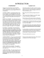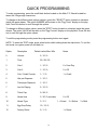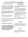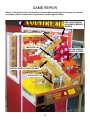
1
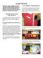
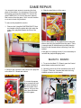
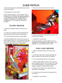
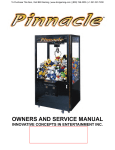
OWNERS AND SERVICE MANUAL
INNOVATIVE CONCEPTS IN ENTERTAINMENT INC.
10123 MAIN STREET, CLARENCE, NY 14031
SERVICE: 1-716-759-0360
FAX: 1-716-759-0884
E-MAIL: [email protected]
WEBSITE: www.icegame.com
1
TABLE OF CONTENTS
INTRODUCTION…………………………….……......PAGE 3
•
•
OVERVIEW
GAME PLAY
QUICK PROGRAMMING INSTRUCTIONS………....PAGE 4
•
OPTIONS
SET-UP / DETAILED PROGRAMMING…………......PAGE 5 & 7
•
•
PROGRAMMING YOUR GAME
PROGRAMMING INSTRUCTIONS
MAINTENANCE………………………………………...PAGE 8
•
•
GENERAL CLEANING
OTHER MAINTENANCE
QUICK TROUBLESHOOTING…………………….....PAGE 9
GAME REPAIR……………………………………..…..PAGE 10 - 17
•
•
•
•
•
•
•
•
•
TROUBLESHOOTING PHILOSOPHY
ACCESSING COMPONENTS
MAIN P.C. BOARD
SCORE SENSOR
EGG LOAD SENSOR
SOLENOID REPLACEMENT
CONVEYOR BELT ASSEMBLY REPLACEMENT
CONVEYOR BELT MOTOR REPLACEMENT
SCORE DISPLAYS
PARTS LISTINGS………………………………...…....PAGE 18
SCHEMATICS……………………………………..…...PAGE 19 - 22
WIRING DIAGRAMS………………………………… .PAGE 23 - 33
WARRANTY INFORMATION………………………....PAGE 34 & 35
ICEDOC CA9001
REVISION
12-19-02
2
INTRODUCTION
OVERVIEW
GAME PLAY
Thank you for purchasing the new COUNTRY
ACRES™ game from I.C.E. We are happy to introduce a great electro-mechanical game with tons of
exciting action.
Game play is simple. The idea is to knock as many
eggs out of the Ferris wheel gondolas as possible in
a given time period. The more eggs you knock out…
The more tickets you win.
COUNTRY ACRES™ was designed with the location serviceman in mind designing both with a high
level of reliability and serviceability. The extensive
use of sub-assemblies makes servicing and cleaning
a snap. The game incorporates some unique features.
Begin the game by inserting enough money for 1
credit.
The conveyor belts will begin to run and the eggs
will start moving around the playfield.
The first time you hit the spin button (or after about
5-10 seconds) the game count down timer will begin.
BARN STYLE CABINET - The cabinet has immediate eye catching appeal to kids of all ages. They just
have to go over to see what it's all about. The all plywood cabinet construction is both very strong and
authentic looking for a game of this type. The plastic
roof "shingles" add a great touch to the look. The
white wood window frames really add to the great
barn look. All glass in the game is 1/4" tempered.
As long as there is time left on the clock, you may try
to knock as many eggs as you can out of the gondolas on the Ferris wheel.
The eggs will fall into the "score" hopper. Each time
an egg goes into the hopper, tickets will be paid out
based on the adjustable settings in game programming.
PLAYFIELD - The playfield is manufactured as a
sub-assembly which is easy to remove should servicing ever be required. The playfield is full of ramps,
slides, conveyor belts and wheels. Along with a spinning game character it is beautiful to watch. At the
same time, game play has been made extremely
easy so kids of all ages can easily play it. Kids just
love to make things happen, and making it happen
easily it what we've accomplished.
As the gondolas are emptied, they will automatically
re-fill as go back around to the top of the game. A
sensor will determine if they are empty and signal a
solenoid gate to release another egg.
The game ends when time runs out.
Please see the programming section of the manual
to determine how to set up your game.
CONVEYOR BELTS - The conveyor belt assemblies
are themselves sub-assemblies making them easy
to service as well. The belts are commercial grade
industrial belts made for years of continual use.
Their use in this product assures a lifetime of trouble
free service. The drive motors have been tested in
excess of 150,000 games with no failures. The motors were chosen for their compact design and extreme reliability for this application.
GREAT GRAPHICS & SOUNDS - The graphics
were chosen for their Kid friendly look. The sounds
are just pure fun.
GAME ELECTRONIC - The game electronics were
chosen for their reliability and serviceability. All of
the game sounds are recorded with a high sample
rate and are played back through a high quality audio amplifier.
3
QUICK PROGRAMMING
To enter programming, press the small black button located on the Main P.C. Board located between the 2 large edge connectors.
To change to the different game option numbers, press the "SELECT" button located on a bracket
inside the game drawer. The option NUMBER will be seen on the "Egg Timer" display on the playfield. Press this button to scroll through the options.
To change to different option values, press the "STEP" button located on a bracket inside the game
drawer. The option VALUE will be seen on the "Egg Counter" display on the playfield. Press this button to scroll through the option values
To exit the programming mode, press the programming button once again.
NOTE: To enter the TEST mode, press select button while holding down the step button. To exit the
test mode, turn game power off and back on.
Option
Description
Default value/ Max / Min
Notes
0
Volume
5 / 10 / 0
1
Time
20 / 99 / 20
2
Coin 1
1 / 10 / 0
0 = Free Play
3
Coin 2
1 / 10 / 0
0 = Off
4
Coin / Credit Counter
1/1/0
1 = Credit
5
Hits per Dispense
1 / 10 / 1
6
Tickets per Dispense
1 / 10 / 1
7
Just for Playing
2 / 10 / 0
8
Ticket Cap
0 / 99 / 0
9
Attract time
3 / 30 / 0 (minutes)
10
Attract Type
3/3/1
11
Egg Drop Delay
10 / 15 / 5
12
Factory Reset
0/1/0
0 = Off
1 = Sound
2 = Motion
1 = Reset
4
3 = Both
SET-UP / DETAILED PROGRAMMING
SAFETY PRECAUTIONS
PROGRAMMING
INSTRUCTIONS
WARNING: WHEN INSTALLING THIS GAME, A 3
PRONG GROUNDED A.C. RECEPTACLE MUST
BE USED. FAILURE TO DO SO COULD RESULT
IN INJURY TO YOURSELF OR OTHERS. FAILURE
TO USE A GROUNDED RECEPTACLE COULD
ALSO CAUSE IMPROPER GAME OPERATION,
OR DAMAGE TO THE ELECTRONICS
To enter programming, press the small black button
located on the Main P.C. Board located between the
2 large edge connectors.
To change to the different game option numbers,
press the "SELECT" button located on a bracket inside the game drawer. The option NUMBER will be
seen on the "Egg Timer" display on the playfield.
Press this button to scroll through the options.
DO NOT DEFEAT OR REMOVE THE GROUNDING
PRONG ON THE POWER CORD FOR THE SAME
REASON AS GIVEN ABOVE. USING AN IMPROPERLY GROUNDED GAME COULD VOID YOUR
WARRANTY.
To change to different option values, press the
"STEP" button located on a bracket inside the game
drawer. The option VALUE will be seen on the "Egg
Counter" display on the playfield. Press this button
to scroll through the option values
HAVE A QUALIFIED ELECTRICIAN CHECK
YOU’RE A.C. RECEPTACLE TO BE SURE THE
GROUND IS FUNCTIONING PROPERLY.
To exit the programming mode, press the programming button once again.
NOTE: To enter the TEST mode, press select button
while holding down the step button. To exit the test
mode, turn game power off and back on.
PROGRAMMING YOUR GAME
This section will give you a detailed explanation of
the functions and operating characteristics of each
of the programming buttons.
OPTION #0
VOLUME
PLEASE READ THIS SECTION CAREFULLY TO
AVOID PROBLEMS WITH YOUR GAME.
This option determines how loud the game volume
will be. The higher the number, the higher the volume. Setting a "0" turns the game sound off. The
range for this option is 0-10. The default value for
this option is "5"
PLEASE NOTE: THE PROGRAMMING BUTTONS
ARE LOCATED INSIDE THE SLIDING DRAWER.
ACCESS THESE BUTTONS BY REMOVING THE
ALLEN BOLTS THAT SECURE THE DRAWER TO
THE CABINET. THERE IS 1 BOLT ON EACH SIDE
OF THE CABINET. AFTER REMOVING THE
BOLTS, PULL OUT ON THE LOG CONTROL
PANEL TO OPEN THE DRAWER.
OPTION #1
TIME
This option determines how long the time of the
game is. The range of this option is 20-99 (20-99
seconds). The default value for this option is
"20" (20 seconds).
5
SET-UP / DETAILED PROGRAMMING
OPTION #2
COIN 1
OPTION #6
TICKETS PER DISPENSE
This option determines how many coins it takes to
earn 1 credit (or play 1 game). The range for this option is 0-10. Setting a "0" puts the game into FREE
PLAY mode. The default value for this option is "1"
This option determines how many tickets are paid
out each time the "dispense command" is given.
This option is handy where the ticket value is very
low and you wish to give away more tickets than you
normally could.
OPTION #3
COIN 2
This option also allows for some interesting possibilities for ticket payouts. EXAMPLE: Lets say you
wanted to pay out 10 tickets BUT ONLY if the player
got 8 eggs. By setting option #5 to 8, and this option
to 10, you would pay out 10 tickets for every 8 eggs
hit.
This option determines how many COIN #1's it takes
to earn a credit (or play 1 game). This option is used
for special instances where a different value of coin
is needed.
The range for this option is 1-10. The default value
for this option is "1" (1 ticket per dispense command,
or egg)
NOTE: FOR MOST APPLICATIONS LEAVE THE
OPTION SET AT "1". FOR OTHER APPLICATIONS, PLEASE CALL OUR SERVICE DEPARTMENT FOR ASSISTANCE. Setting a "0" turns this
coin mech OFF.
OPTION #7
JUST FOR PLAYING
OPTION #4
COIN / CREDIT COUNTER
This option is handy for giving out tickets "just for
playing" the game. This is handy when the kids playing are very young or not talented and have a hard
time scoring. This assures the customer will walk
away with a pre-determined minimum amount of
tickets. This is also handy in jurisdictions that insist
on a guaranteed payout.
This option determines whether the game counter
will register individual coins or credits (games
played). The range for this option is 0-1. Setting a
"0" sets the game up to work on coins. Setting a "1"
sets the game to work on credits. The default value
for this option is "1".
The range for this option is 0-10. Setting a "0" turns
this option OFF. The default value for this option is
2. (2 ticket minimum)
OPTION #5
HITS PER DISPENSE
OPTION #8
TICKET CAP
This option determines how many eggs must be
scored before a "dispense command" is given. This
option is handy if you have a high ticket value and
you wish to dispense fewer tickets.
This option limits the amount of tickets that can be
paid out. For instance, you may wish to have a long
game time to assure that younger players have a lot
of fun and can get tickets, but you don't want to
overpay with older more skilled players. By enabling
the ticket cap, you can determine the maximum
amount of tickets you will pay out. The range of this
option is 0-99. Setting a "0" turns this option OFF.
The default value for this option is "0". (Off)
EXAMPLE: You could set this option to 5, and option
#6 to "1". This would mean that each time you
scored 5 eggs, you would get 1 ticket.
The range for this option is 1-10. The default value
for this option is "1". ( 1 ticket per egg scored)
6
SET-UP / DETAILED PROGRAMMING
OPTION #9
ATTRACT TIME
OPTION #12
FACTORY RESET
This option determines how long a period of time
transpires BETWEEN attract modes. The range for
this option is 0-30 (0-30 minutes). Setting a "0" turns
the attract mode OFF. The default value for this option is "3" (once every 3 minutes).
This option will reset ALL programming options to
their factory default values at one time. The range
for this option is 0-1. Setting a "1" will reset all values. The default value for this option is "0".
OPTION #10
ATTRACT TYPE
This option determines which TYPE of attract mode
will be performed. The range for this option is 1-3.
1= Sound Only
2= Motion Only
3= Sound AND Motion
The default value for this option is "3" (both)
OPTION #11
EGG DROP DELAY
When a gondola is empty, a sensor sees that it is
empty and sends a signal to the game computer to
dispense an egg. The positioning of the sensor requires a delay between the sensing and the dispensing of the egg. Since there are mechanical variations
from motor to motor, the drop delay time might not
be the same from game to game. Also, as the game
gets older, the gears wear in and the internal mechanical resistance in the gear box goes down making it run faster. To compensate for this, the delay
time is adjustable.
If the eggs drop too soon, increase the value of the
option. If the eggs drop too late, decrease the value
of the option. The range for this option is 5-15 (5-15
milliseconds. The default value for this option is "10"
7
MAINTENANCE
DRIVE O-RINGS - After a long period of time, the
urethane o-rings may become more brittle and slippery. If you notice this, simply pop the old o-rings off
and replace.
GENERAL CLEANING
WARNING: DISCONNECT POWER WHEN WORKING ON THE INTERIOR OF THE GAME AS HIGH
VOLTAGE A.C. POWER MAY BE PRESENT.
CONVEYOR BELT BEARINGS - The bearings are
lubed at the factory and will normally never require
and additional lubrication. However if you notice any
squeaking sounds the end of the bearing may be
LIGHTLY lubricated with common motor oil.
CABINET - Since the cabinet is constructed of a
rough finish wood the best way to clean heavy dirt is
to spray a cleaner such as Fantastic™ or Formula
409™ on the cabinet, brush the cleaner onto the
surface, then wipe with a LINT LESS cloth.
LIGHTING - The game uses a single PLL style florescent light bulb for game lighting. This bulb can be
purchased at any lighting supply house or from I.C.
E. The bulb type is: PL-L 40W/41/RS/IS. Simply
snap a new one into position to replace.
GLASS - Any commercially available glass cleaner
will work well, however aerosol products work best.
INSIDE PLAYFIELD - It is necessary to keep the inside of the playfield surfaces slippery for the eggs to
slide through the different chutes properly. Vacuum
all loose debris from the playfield then apply a good
coat of spray type furniture polish such as
PLEDGE™. This product also works well for cleaning the clear plastic guards.
IMPORTANT: IF YOU REMOVE THE PLAYFIELD
FOR ANY MAINTENANCE, BE SURE NONE OF
THE GAME HARNESSING GETS PINCHED WHEN
RE-INSTALLING THE PLAYFIELD.
NOTE: ALWAYS REMEMBER TO INSTALL
THE BOLTS THAT SECURE THE DRAWER TO
THE CABINET WHEN YOU ARE DONE SERVICING THE GAME.
EGGS - Clean the eggs with Fantastic™ or Formula
409™ and a small brush. Polish with a spray furniture polish such as PLEDGE™ when done.
OTHER MAINTENANCE
NOTE: The proper amount of eggs in the game is
necessary to avoid either jam ups (from too many)
or reduced play value (from too few). The proper
amount of eggs for the game is 2 dozen (24).
Most of the game is maintenance free, however you
should check the following occasionally to be sure
that all is in order.
TOOTHED DRIVE BELT - Check periodically for excessive wear. If excessive wear is noted, replace the
belt and check that the pulleys are properly aligned
and that the set screws are tight. Also check that the
motor tension spring is attached and working properly.
8
QUICK TROUBLESHOOTING
PROBLEM
PROBABLE CAUSE
SOLUTION
Game won't take or add money
correctly
Bad coin switch
Bad harnessing
Bad Main P.C. Board
Improper game programming
Replace coin switch
Check w / meter and repair as necessary
Check and repair or replace if necessary
Check settings and program if necessary
Character won't spin and hit targets
Control panel button bad
Bad harnessing
Bad spin gear motor or limit switch
Replace button
Check and repair or replace if necessary
Replace gear motor
No or Low game sound
Bad speaker
Volume set too low
Bad or disconnected speaker wiring
Bad Main P.C. Board
Check connections and replace if
needed
Check programming and adjust
Check wiring
Repair or replace Main P.C. Board
Tickets will not dispense or dispense improperly
Bad or Dirty Ticket dispenser
Bad Harnessing
Bad Main P.C. Board
Programming settings incorrect
Score sensor bad or disconnected
Repair or replace Ticket Dispenser
Repair or replace harnessing
Repair or replace Main P.C. Board
Check programming and adjust if needed
Repair or replace if necessary
Score sensor will not work properly Bad or dirty sensor
Bad harnessing
Bad Main P.C. Board
Clean or replace as necessary
Repair harnessing
Repair or replace Main P.C. Board
Eggs will not load or keep loading
Hopper fill sensor dirty or not working
Gondola sensor mirror missing or dirty
Sensor wiring bad
Egg drop delay programming set incorrectly
Clean or replace sensor as necessary
Clean or replace mirror as needed
Check and repair harnessing as needed
Check programming adjust if necessary
Ferris Wheel won't turn or turns
intermittently
Bad or broken drive belt
Bad drive Motor
Belt tension spring broken or missing
Loose drive pulley
Bad motor harnessing
Bad Main P.C. Board
Repair or replace as necessary
Replace drive motor
Replace tension spring
Check both pulleys and tighten as
needed
Check and repair harnessing as needed
Repair or replace Main P.C. Board
Conveyor belts won't run or run
intermittently
Bad or broken drive o-ring
Bad drive motor
Loose drive pulley
Bad motor harnessing
Bad Main P.C. Board
Replace o-ring
Replace drive motor
Check pulley and tighten as necessary
Repair harnessing as necessary
Repair or replace Main P.C. Board
Eggs get caught and jammed up
Dented or cracked egg
Eggs and pathways dirty
Deflector plastic on top chute broken
Remove and replace bad eggs
Clean and polish with Furniture polish
Replace broken deflector
Game dead - won't work at all
Broken power cord
Blown main power fuse
Bad harnessing to main transformer
Replace power cord
Replace fuse in power module
Check and repair harnessing
Game continuously locks or
freezes up
Bad A.C. ground causing excess static build
up
Check internal harness grounds
Voltage regulator on Main P.C. Board bad
Check cord and outlet for good ground
Repair as needed
Repair or replace Main P.C. Board
9
GAME REPAIR
Shown in the photo below, are locations of serviceable components. Procedure for removal
and repair of these components may be found on the pages to follow.
EGG LOAD SENSOR
& SOLENOID BEHIND
HOPPER
MOTOR UNDER CONVEYOR BELT
TIMER DISPLAY
SCORE SENSOR
BEHIND HOPPER
MOTOR UNDER CONVEYOR BELT
SCORE DISPLAY
10
GAME REPAIR
ACCESSING COMPONENTS
WARNING: ALWAYS REMOVE POWER TO
THE GAME BEFORE ATTEMPTING ANY
SERVICE, UNLESS NEEDED FOR SPECIFIC
TESTING. FAILURE TO OBSERVE THIS
PRECAUTION COULD RESULT IN SERIOUS
INJURY TO YOURSELF OR OTHERS.
All components in the game are accessed by opening up the control panel drawer on the front of the
game. To open the drawer, remove the 2 Allen
screws (1 on each side of the game) that secure the
drawer in place.
TROUBLESHOOTING
PHILOSOPHY
To find problems with this game, always first check
what should be obvious. See that the game is
plugged in, and all of the fuses on the game are
good.
Next, check to see that all of the connectors are
firmly seated, and that none of the wires have pulled
out of them.
When trying to find out if specific components are
bad or not, try swapping them with components from
another player station to see if the problem moves
with the component, or stays where it was. This will
help you to know if you have a problem with a specific component, or maybe a problem with either the
wiring or the Main P.C. Board. Use extreme caution
when using probes or volt-meters if the game is
powered up. If checking continuity, it is important to
disconnect the harnessing at both ends, as attached
they may yield erroneous results.
Pull on the front of the control panel and the drawer
will open.
If P.C. Boards are suspected as causing problems,
check to see that all I.C. chips are firmly seated on
the boards.
Once the drawer is opened, you will notice that you
now have access to the Main P.C. Board and the associated programming buttons.
MAIN PCB
11
PROGRAMMING BUTTONS
GAME REPAIR
You now also have access to removing the front
glass of the cabinet. It is necessary to remove the
front glass to access the playfield. To remove the
glass CAREFULLY lift it out of the lower channel,
then remove from the game. Set it in a safe location
so as not to break it by accident.
4. Slide the playfield out of the game.
To remove the playfield for service:
1. Remove the 2 playfield SHIPPING BOLTS that
are located under the guide rails right under the
sides of the playfield towards the front of the
game.
NOTE: Many items on the playfield can be serviced
without removing the playfield from the game. There
is enough slack in the harnessing to allow the playfield to be slid forward without removing it from the
cabinet.
If the game is not being moved, it is not necessary to
re-install the playfield shipping bolts.
MAIN P.C. BOARD
1. To service the Main P.C. Board, open the Control
panel drawer and access the board.
2. Carefully remove all of the connectors from the P.
C. Board. (There are 2 screws that retain the long
JAMMA connector to the board).
2. Remove the connectors that connect the playfield
to the Main P.C. Board and cabinet.
3. Loosen the square
drive screws that hold
the glass channels to
the front sides of the
cabinet. Lift up on the
rails, then slide them
out of the game.
12
GAME REPAIR
3. Remove the plastic hex Standoffs that secure the
board to the cabinet.
5. Remove the connector to the score sensor.
4. Re-assemble in reverse order
NOTE: DON'T FORGET TO RE-INSTALL THE 2
SCREWS THAT SECURE THE JAMMA HARNESS
TO THE BOARD. FAILURE TO REPLACE THE
SCREWS CAN RESULT IN INTERMITTENT
OPERATION OF THE GAME OR COMPLETE
FAILURE.
SCORE SENSOR
1. Open control panel drawer and remove front
glass.
2. Loosen the square drive screws that fasten the
glass side rails to the front sides of the cabinet.
6. Remove the hardware that secures the score sensor to the score hopper.
3. Lift up, then slide the rails out of the cabinet.
7. Assemble in reverse order.
4. Slide the playfield about 2/3rds of the way out to
make it easier to work on. You can allow it to tilt onto
the control panel drawer. The drawer has been designed to support the weight of the playfield.
NOTE: BE CAREFUL TO BE SURE THAT THE
CONNECTOR IS PROPERLY INSTALLED. IF NOT,
DAMAGE TO THE SENSOR MAY OCCUR.
EGG LOAD SENSOR
1. Open control panel drawer and remove front
glass.
2. Loosen the square drive screws that fasten the
glass side rails to the front sides of the cabinet.
3. Lift up, then slide the rails out of the cabinet.
4. Slide the playfield about 2/3rds of the way out to
make it easier to work on. You can allow it to tilt onto
the control panel drawer. The drawer has been designed to support the weight of the playfield.
5. Remove the connector to the egg load sensor.
(See photo on next page)
6. Carefully remove the sensor and replace with a
new sensor.
7. Assemble in reverse order.
13
GAME REPAIR
NOTE: BE SURE TO SEE THAT THE ORANGE
STRIPED WIRE GOES TO THE BANDED SIDE OF
THE DIODE ON THE SOLENOID WHEN REINSTALLING THE FAST-ON'S.
6. Remove the cotter pin from the solenoid. Discard
the old cotter pin.
NOTE: BE CAREFUL TO BE SURE THAT THE
CONNECTOR IS PROPERLY INSTALLED. IF NOT,
DAMAGE TO THE SENSOR MAY OCCUR.
SOLENOID REPLACEMENT
1. Open control panel drawer and remove front
glass.
7. Remove the three (3) Allen bolts and hex nuts
that mount the egg load hopper to the plastic panels.
2. Loosen the square drive screws that fasten the
glass side rails to the front sides of the cabinet.
3. Lift up, then slide the rails out of the cabinet.
4. Slide the playfield about 2/3rds of the way out to
make it easier to work on. You can allow it to tilt onto
the control panel drawer. The drawer has been designed to support the weight of the playfield.
5. Remove the Fast-on connectors to the solenoid.
NOTE: BE CAREFUL TO NOT LOSE THE SOLENOID SPRING. THE GAME WILL NOT WORK
PROPERLY WITHOUT THIS SPRING.
8. Remove the egg load hopper from the game.
9. Remove the two (2) screws that secure the solenoid and sensor mounting bracket to the plastic panels. (See photo on next page)
14
GAME REPAIR
ORANGE
STRIPED WIRE
BAND ON DIODE
10. Install the new solenoid body to the game by installing the mounting screws through the plastic
panel and sensor mounting bracket, and into the solenoid.
16. Re-connect the Fast-ons to the solenoid tabs.
NOTE: BE SURE TO SEE THAT THE ORANGE
STRIPED WIRE GOES TO THE BANDED SIDE OF
THE DIODE ON THE SOLENOID WHEN REINSTALLING THE FAST-ON'S
11. Slide the solenoid plunger into the solenoid body
and carefully slide the solenoid spring onto the
plunger.
12. Carefully re-align the egg load hopper to the
game making sure that as you install it, the egg
loading lever goes into the slot in the solenoid
plunger.
17. Re-assemble the playfield into the game and
check for proper operation.
13. Re-install and tighten the three (3) Allen bolts
and hex nuts that secure the egg load hopper to the
plastic panels.
CONVEYOR BELT ASSEMBLY
REPLACEMENT
14. Install a new cotter pin making sure that the solenoid spring is kept between the solenoid and the
cotter pin.
Replacement of the conveyor belt and motor is done
as a sub-assembly. Information on motor replacement follows:
15. Bend the cotter pin over to avoid it hitting and
binding on anything.
1. Open control panel drawer and remove front
glass.
NOTE: IT IS IMPERATIVE THAT THE EGG LOAD
LEVER WORKS SMOOTHLY WITH NO BINDING.
IF ANY BINDING IS NOTICED, LOOSEN THE ALLEN BOLTS AND HEX NUTS THAT SECURE THE
EGG LOAD HOPPER TO THE PLASTIC PANELS
AND RE-POSITION SO THAT THERE IS NO BINDING ON THE EGG LOAD LEVER. RE-TIGHTEN
THE BOLTS.
2. Loosen the square drive screws that fasten the
glass side rails to the front sides of the cabinet.
3. Lift up, then slide the rails out of the cabinet.
4. Slide the playfield about 2/3rds of the way out to
make it easier to work on. You can allow it to tilt onto
the control panel drawer. The drawer has been designed to support the weight of the playfield.
5. Unplug the connector from the conveyor assembly.
15
GAME REPAIR
6. Remove the four (4) Allen Bolts that secure the
conveyor to the plastic panels and slide up and out
of the playfield.
NOTE: BE SURE THAT THE PADDLES ON THE
CONVEYOR DO NOT HIT THE METAL HOPPERS
AFTER INSTALLATION.
NOTE CLEARANCE
When replacing the front conveyor, there are adjustable bolts on the left hand hopper to assure that it is
set as close as possible to the conveyor, but not
touching the conveyor paddles. If set too far from the
paddles, binding of the eggs might occur.
NOTE: YOU MAY HAVE TO REMOVE OR
LOOSEN ADDITIONAL HARDWARE FOR THE
CONNECTOR TO CLEAR THE PLASTIC PANELS
DEPENDING ON WHICH CONVEYOR YOU ARE
REMOVING.
CONVEYOR BELT MOTOR
REPLACEMENT
You may now either send the conveyor unit in to
I.C.E. for service, or you may proceed to the next
section to service the motor.
1. Remove the conveyor assembly as instructed
above.
7. Re-assemble in reverse order.
2. Set the conveyor assembly on the edge of a table
and punch out one of the retaining pins that hold the
belt together. You will see that one side of the pins
has a head on it similar to that of a nail. Punch the
pin out from the OPPOSITE side. The belt will now
fall off the conveyor unit exposing the motor.
16
GAME REPAIR
SCORE DISPLAYS
PUNCH OUT PIN FROM
OTHER SIDE OF BELT
1. Open control panel drawer and remove front
glass.
2. Loosen the square drive screws that fasten the
glass side rails to the front sides of the cabinet.
3. Lift up, then slide the rails out of the cabinet.
4. Slide the playfield about 2/3rds of the way out to
make it easier to work on. You can allow it to tilt onto
the control panel drawer. The drawer has been designed to support the weight of the playfield.
5. Remove the connectors from the display. (See
photo)
3. Unsolder and remove the old motor.
NOTE THE POLARITY ON THE WIRES OR THE
NEW MOTOR COULD RUN BACKWARDS.
6. Remove the plastic hex nuts that secure the displays to the plastic panels. Remove the displays.
4. Install the new motor. Be sure the polarity is correct and be sure that the wiring is secured out of the
way so it can't get caught on the conveyor belting.
7. Re-assemble in reverse order.
IF YOU HAVE ANY QUESTIONS REGARDING
GAME REPAIRS, PLEASE CONTACT OUR
SERVICE DEPARTMENT
5. Re-install the belt. Be sure the sprockets are lined
up correctly. Slide the pin through the belting and
tap into place.
PHONE:
FAX:
E-MAIL:
6. Re-assemble in reverse order.
HINT: IF THE EGGS ARE REMOVED FROM THE
GAME, YOU CAN PLUG THE UNIT INTO THE
GAME TO MAKE SURE IT WORKS BEFORE REINSTALLING ANYTHING. YOU CAN ALSO TEST
THAT THE MOTOR WORKS BY CONNECTING TO
A 12VDC SUPPLY IF YOU HAVE ONE
AVAILABLE.
17
1-716-759-0360
1-716-759-0884
[email protected]
PARTS LISTING
MECHANICAL PARTS
FP1004
CA1010X
FP1019
CA1063
CA3001
BG3002
CA3006
CA3027
CA3028
CA3020
CA3030
CA3040
CA3042
CA4001
CS4003
5011
DECALS / GRAPHICS
LEG LEVELER MOUNTING BRACKET
CONVEYOR ASSEMBLY
LEVELER FOOT, LONG
MOTOR TENSIONING SPRING
EGG
4" SPEAKER GRILL
SHINGLE PANEL
FRONT GLASS
SIDE GLASS
EGG RELEASE ARM
GONDOLA SENSOR MIRROR
CONVEYOR BELT
CONVEYOR GEAR SPROCKET
TIMING BELT
CONVEYOR DRIVE O-RING (MOTOR)
SOLENOID SPRING
CA7001
CA7002
CA7004
CA7005
CA7010
CA7011
CA7012
CA7018
CA7020
CA7021
CA7022
7021
7032
7033
7035
CA7053
CA7052
ELECTRONIC / ELECTRICAL
PARTS
PP2002X
HR2005
DD2007X
FP2007
2008
CS2008X
BW2017
BW2018
CC2027
2027G
CG2032X
PP2034X
CA2039X
2289X
HH5005D
8312
CS8449X
TRANSFORMER ASSEMBLY
LARGE ROUND PUSH BUTTON, WHITE
POWER MODULE ASSEMBLY
4" SPEAKER
SOLENOID
GLOBE MOTOR ASSEMBLY
PLASTIC BULB CLIP
PLASTIC BULB SUPPORT
POWER CORD
FAN GUARD
DISPLAY P.C. BOARD
MAIN P.C. BOARD
EGG/SCORE SENSOR P.C. BOARD
RESET BUTTON ASSEMBLY
TICKET DISPENSER (DELTRONICS)
FLUORESCENT BULB, PL-L 40W/41/RS/IS
LIGHT BALLAST ASSEMBLY
18
CHICKEN FEED BAG DECAL
ICE LOGO
CONTROL PANEL OVERLAY DECAL
BUTTON DECAL
LOWER CONVEYOR FRONT DECAL
LOWER CONVEYOR REAR DECAL
UPPER CONVEYOR FRONT DECAL
SCORE HERE DECAL
PROGRAMMING DECAL
TARGET DECAL
CONVEYOR BASE DECAL
SERIAL NUMBER TAG
FUSE REPLACEMENT WARNING DECAL
POWER DISCONNECT WARNING DECAL
ON / OFF POWER DECAL
PLAYFIELD DECAL
INSIDE REAR DECAL (BACKGROUND)
19
20
21
22
23
1
2
yellow
yellow/black
TWIST WIRES
A
B
4
2 PIN CAP #2181
FEMALE PIN
#2102
3
19 "
TITLE
CONVEYER MOTOR
#CS2008
DATE
2
DESCRIPTION
7/30/02
ASSEMBLY
REVISED
11/15/02
#CA2008CX - CONVEYER MOTOR
COUNTRY ACRES
1
PAGE
DRAWN BY
FILENAME
1 OF 11
MMARTIN
CA1000X.VSD
#CS2008 - MOTOR GLOBE
415A-541
A
B
C
1
C
2
D
3
D
4
24
A
B
4
1
2
red
red/black
TWIST WIRES
3
2 PIN CAP #2181
FEMALE PIN
#2102
8"
DATE
2
DESCRIPTION
TITLE
#CS2008 - MOTOR GLOBE
415A-541
7/30/02
ASSEMBLY
REVISED
11/15/02
COUNTRY ACRES
#CA2008WX - WHEEL MOTOR
WHEEL MOTOR
#CS2008
1
PAGE
DRAWN BY
FILENAME
CA1000X.VSD
2 OF 11
MMARTIN
A
B
C
1
C
2
D
3
D
4
25
A
B
4
To Transformer
#PC20217
3
GREEN/YELLOW
24 "
DATE
2
DESCRIPTION
TITLE
#PC20217
7/30/02
REVISED
11/15/02
COUNTRY ACRES
#CA2056X - GROUND HARNESS
GREEN/YELLOW
To Door, Lower
Screw
1
PAGE
DRAWN BY
FILENAME
CA1000X.VSD
3 OF 11
MMARTIN
A
B
C
1
C
2
D
3
D
4
26
A
B
C
D
DATE
DESCRIPTION
TITLE
7/30/02
4
REVISED
11/15/02
COUNTRY ACRES
15 PIN PLUG #2144
SPLIT PIN #2100
PIN 2: 20-14 AWG MALE #8260
PIN 15: KEY PLUG #2549
KEY
ORANGE
orange *3
violet/blue
violet/white
BLACK
gray/yellow
gray/brown
black
gray/red
violet/orange
black
violet/green
#CA2050X - DOOR HARNESS
1
2
3
4
5
6
7
8
9
10
11
12
13
14
15
4
39 "
#2815
PAGE
DRAWN BY
FILENAME
#2558
#2558
3
4 OF 11
MMARTIN
CA1000X.VSD
violet/green
39 "
orange
39 "
violet/orange
17 "
3
red
black
black
red
23 "
T Sense
P GND
T Run
+ 12VDC
1 + 12VDC
2 T Out
0000000000
TICKET
0000000000
COIN
black
#PC20224
12v COUNTER
#PC20224
12v COUNTER
#651
.187
2
To Low Ticket
Switch
#651
.187
2 PIN MOLEX HOUSING #2089
MINI KK PIN #2074
violet/green
orange
violet/green
10 "
1
2
3
4
To Ticket
Dispenser
53 "
orange
black
gray/red
black
gray/brown
gray/yellow
8"
#648
.250
#648
.250
#648
.250
#648
.250
#651
.187
#651
.187
#651
.187
gray/yellow
#650
.110
black
#651
.187
#650
.110
#650
.110
#650
.110
orange
8"
black
orange
orange
6"
49-1/2 "
8"
56-1/2 "
8"
57 "
RED FLASHING LED #8212
WITH LED HOLDER #1017
4 PIN MLX CAP #2158
MLX FEMALE PIN #2176
PINS 2 & 4: 20-14 AWG MLX FEMALE PIN #8177
violet/blue
BLACK + black
violet/white
ORANGE + orange
62 "
2
1
To Coin Switch 2
To Coin Switch 1
To Lockout
Coils
To Lockout
Coils
To Coin Lamps
To Coin Lamps
1
A
B
C
D
27
A
B
C
D
+12 VDC
Gondola Signal 1
GND
Gondola Signal 2
1
2
3
4
5
6
1
2
3
4
5
6
4
KEY #2991
KEY
orange
white/orange
black
white/yellow
KEY 6 PIN IDC #8634
KEY #2991
KEY
orange
white/brown
black
white/red
KEY 6 PIN IDC #8634
BLACK/BLUE
#638
.187
Solenoid
+12 VDC
Egg Score Signal 1
GND
Egg Score Signal 2
ORANGE/WHITE
2 PIN PLUG #2103
SOLID PIN #2100S
red
red/black
6 PIN AMP HOUSING #2944
CONTACT PIN #2201
black
white/green
violet/black
violet
2 PIN PLUG #2103
SOLID PIN #2100S
yellow
yellow/black
2 PIN PLUG #2103
SOLID PIN #2100S
yellow
yellow/black
#638
.187
1
2
1
2
3
4
5
6
1
2
1
2
+12 VDC
+5 VDC
Wheel Motor
GROUND
CHUCK-E Home
+24 VDC
CHUCK-E MOTOR
+ 12 VDC
Conveyer
+ 12 VDC
Conveyer
4
63-1/2 "
45-1/2 "
58-1/2 "
33 "
41-1/2 "
41-1/2 "
3
3
49 "
38-1/2 "
DATE
2
DESCRIPTION
TITLE
2
1
2
3
4
5
6
7
8
9
10
11
12
13
14
15
7/30/02
REVISED
11/20/02
#CA2051X - PLAYFIELD HARNESS
COUNTRY ACRES
1/2 " Spiral - #2955 @ 14 "
15 PIN PLUG #2144
SPLIT PIN #2100
PIN 8: 20-14 AWG
#8260
yellow *2
violet
red
ORANGE/WHITE
orange *2
yellow/black *2
violet/black
black *3
white/green
red/black
BLACK/BLUE
white/brown
white/red
white/orange
white/yellow
1
PAGE
DRAWN BY
FILENAME
1
5 OF 11
MMARTIN
CA1000X.VSD
A
B
C
D
28
A
B
C
D
Switch
Light
STEP
SELECT
.250 #653T
.250 #653T
.250 #653T
.250 #653T
1
2
3
4
5
6
7
8
9
10
11
12
13
14
15
brown/gray
red/gray
brown/gray
red/gray
4
black
black
2"
#2289X - BUTTON ASY
black
black
2"
#2289X - BUTTON ASY
#650
#651
#650
#651
violet/red
black
#2909
.187
#2909
M
.187
#2909
M
.187
#651
#651
#651
#651
37 "
43-1/2 "
#2909
M
.187
M
15 PIN CAP #2367
FEMALE PIN #2102
YELLOW
violet
red
ORANGE/WHITE
ORANGE
yellow/black
violet/black
BLACK
white/green
red/black
black/blue
white/brown
white/red
white/orange
white/yellow
violet/brown
orange
4
black
gray/blue
black
gray/green
21 "
30 "
30 "
39-1/2 "
3
50 "
50 "
50 "
Attach "SWITCH" label
around these wires
6"
A
1
2
C
22
Z
16
14
13
17
L
d
f
U
Y
28
26
B
3
27
3
19
E
5
T
24
gray
black/blue
black
1
2
3
4
5
6
7
8
9
10
11
12
13
14
15
1
2
3
15 PIN CAP #2367
FEMALE PIN #2102
KEY
ORANGE
ORANGE
violet/blue
violet/white
BLACK
gray/yellow
gray/brown
black
gray/red
violet/orange
black
violet/green
DATE
2
DESCRIPTION
TITLE
7/30/02
COUNTRY ACRES
REVISED
1
12
c
9
10
M
25
18
N
11
21
R
20
12/2/02
1
PAGE
DRAWN BY
FILENAME
6 OF 11
MMARTIN
CA1000X.VSD
Tipp 122 & heatsink in
drawer assembly #CA3085X
28-1/2 "
#CA2052X - MAIN CABINET HARNESS
3 PIN MINI KK HOUSING #2090
MINI KK PIN #2074
13 "
13 "
2
A
B
C
D
29
A
B
C
D
4
4
SOLENOID
LOCKOUT COIL
CHUCK-E MOTOR
WHEEL MOTOR
CONVEYER MOTORS
EGG SENSE 1
GOND. EMPTY 2
COIN 1
ADV BUTTON
TICKET CNTR
COIN CNTR
BUTTON LIGHT
KEY
GROUND
T-SENSE
T-RUN
COIN 2/DBV
+ 12 VDC
GOND. EMPTY 1
EGG SENSE 2
SEL BUTTON
SPEAKER +
SPIN BUTTON
CHUCK-E HOME
1
2
3
4
5
6
7
8
9
10
11
12
13
14
15
16
17
18
19
20
21
22
23
24
25
26
27
28
3
gray
gray/yellow
violet/black
red/black
yellow/black
white/brown
white/yellow
gray/brown
gray/blue
violet/green
violet/orange
violet/brown
violet/blue
violet/white
gray/red
ORANGE
white/orange
white/red
KEY
gray/green
red/gray
violet/red
white/green
3
+
+
+
+
12 VDC
24 VDC
24 VDC
5 VDC
+ 12 VDC
+ 12 VDC
GROUND
GROUND
GROUND
+ 12 VDC
GROUND
GROUND
SPEAKER GROUND
GROUND
+ 18 VDC
GROUND
+ 18 VDC
KEY
+18 VDC
GROUND
+ 12 VDC
GROUND
GROUND
DATE
2
DESCRIPTION
TITLE
2
7/30/02
A
B
C
D
E
F
H
J
K
L
M
N
P
R
S
T
U
V
W
X
Y
Z
a
b
c
d
e
f
REVISED
12/6/02
COUNTRY ACRES
CARD EDGE PINOUT
red
ORANGE
violet
ORANGE
orange
black
ORANGE/WHITE
black
YELLOW
BLACK
black
KEY
black
brown/gray
BLACK
black
1
PAGE
DRAWN BY
FILENAME
1
7 OF 11
MMARTIN
CA1000X.VSD
A
B
C
D
30
A
B
C
D
4
4
To Fan
To Board
1
2
3
6 PIN PLUG #2173
PINS 3&6: SOLID PIN #2100S
PINS 1,2,4,5: MALE PIN #2014
YELLOW (12 AWG)
ORANGE (12 AWG)
RED (18 AWG)
YELLOW (12 AWG)
ORANGE (12 AWG)
RED (18 AWG)
3 PIN CAP #2288
FEMALE #2102
BLACK
GREEN
WHITE
1
2
3
4
5
6
P4
3
3
#8173 - SVT
51 "
42 "
DATE
2
DESCRIPTION
TITLE
2
1
2
3
4
5
6
1
2
3
7/30/02
REVISED
EXTENSION HARNESS
#CA2053X - FAN/TRANSFORMER
11/15/02
1
PAGE
DRAWN BY
FILENAME
To Power Module
COUNTRY ACRES
3 PIN PLUG #2206
SOLID PIN #2100S
BLACK
GREEN
WHITE
6 PIN CAP #2366
PINS 3&6:FEMALE PIN #2102
PINS 1,2,4,5:FEMALE PIN #8269
YELLOW (12 AWG)
ORANGE (12 AWG)
RED (18 AWG)
YELLOW (12 AWG)
ORANGE (12 AWG)
RED (18 AWG)
To
Transformer
1
8 OF 11
MMARTIN
CA1000X.VSD
A
B
C
D
31
A
B
C
D
4
4
1
2
3
4
5
6
7
8
9
10
11
12
P3
MAIN
3
12 PIN PLUG #2106
SPLIT PIN #2100
brown
red/black
orange/black
yellow
green
blue
ORANGE
gray
white
black/white
tan
BLACK
3
50 "
TWISTED WIRES
DATE
2
DESCRIPTION
TITLE
12 PIN PLUG #2106
SPLIT PIN #2100
7/30/02
REVISED
11/15/02
COUNTRY ACRES
#CA2054X - DISPLAY HARNESS
1
2
3
4
5
6
7
8
9
10
11
12
P1
DISPLAY
brown
red/black
orange/black
yellow
green
blue
ORANGE
gray
white
black/white
tan
BLACK
2
1
PAGE
DRAWN BY
FILENAME
1
9 OF 11
MMARTIN
CA1000X.VSD
A
B
C
D
32
A
B
C
D
1
2
3
4
5
6
7
1
2
3
4
5
6
7
P2
4
4
3
DATE
2
DESCRIPTION
7/30/02
HARNESS
REVISED
11/15/02
#CA2057X - DISPLAY INNERCONNECT
COUNTRY ACRES
1
1
2
3
4
5
6
7
1
2
3
4
5
6
7
P3
1
PAGE
DRAWN BY
FILENAME
7 PIN IDC #2091
7 PIN IDC #2091
TITLE
violet/brown
violet/red
violet/orange
violet/yellow
violet/green
violet/blue
violet
violet/brown
violet/red
violet/orange
violet/yellow
violet/green
violet/blue
violet
gray/brown
gray/red
gray/orange
gray/yellow
gray/green
gray/blue
gray/violet
7 PIN IDC #2091
26 "
Twisted
2
7 PIN IDC #2091
gray/brown
gray/red
gray/orange
gray/yellow
gray/green
gray/blue
gray/violet
3
10 OF 11
MMARTIN
CA1000X.VSD
A
B
C
D
33
A
B
C
D
1027
2364G
2764
6146
SK624
4
2
1
4
4
4
PART #
QTY
4
DESCRIPTION
1
2
3
3
3 PIN PLUG #2206
SOLID PIN #2100S
black
GREEN/YELLOW
black
BRACKET (HEAT SINK 'L')
FAN GUARD (FG-8) METAL 80MM
FAN 110V AC (SUNON SF-11580A-1
6-32 x 2 PPHMS
6-32 KEP NUT
3
DATE
2
DESCRIPTION
TITLE
#PC20217
7/30/02
REVISED
11/15/02
COUNTRY ACRES
#CA2764X - FAN ASSEMBLY
GREEN/YELLOW
11 "
2
1
PAGE
DRAWN BY
FILENAME
1
11 OF 11
MMARTIN
CA1000X.VSD
A
B
C
D
Warranty
I.C.E warrants all components in the COUNTRY ACRES™ game to be free of
defects in materials and workmanship for a period of 90 days from the date of
purchase. Furthermore, all MAIN P.C. BOARDS are warranted for 180 days.
This warranty does not cover items damaged due to normal wear and tear,
subjected to abuse, improperly assembled by the end user, modified, repaired, or
operated in a fashion other than that described in the service manual.
If your COUNTRY ACRES™ game fails to conform to the above-mentioned
warranty, I.C.E.'s sole responsibility shall be at its discretion to repair or replace
any defective component with a new or remanufactured component of equal to or
greater O.E.M. specification.
I.C.E. will assume no liability whatsoever, for costs associated with labor to replace
defective parts, or travel time associated therein.
I.C.E.'s obligation will be to ship free of charge, replacement parts by U.P.S.
Ground, U.S. mail, or other comparable shipping means. Any express mail or
overnight shipping expense is at the cost of the purchaser.
Products will be covered under warranty only when:
·
The serial number of the game with the defective parts is given.
·
The serial number of the defective part, if applicable, is given.
·
Defective parts are returned to I.C.E., shipping pre-paid, in a timely fashion, if
requested by I.C.E.
·
A copy of the sales receipt is available as proof of purchase upon request of
I.C.E.
I.C.E. distributors are independent, privately owned and operated. In their judgment, they may sell parts or accessories other than those manufactured by I.C.E.
We cannot be responsible for the quality, suitability, or safety of any non-I.C.E.
part, or any modification, including labor, which is performed by such a distributor.
34
WARRANTY
ICE Inc warrants that all of its products will be free from defects in material and workmanship.
When placing a warranty request, please be prepared to provide the following information:
•
•
•
Serial Number of Game or Bill of Sale
Machine Type
A Detailed Description of the Equipment Fault Symptoms
ICE product, including Cromptons, Sam’s Billiards, Uniana and Bell Fruit is warranted as follows:
•
•
•
•
•
180 days on the Main PCB and Computers
90 days on all other components (i.e. DBV’s, Ticket Dispensers, etc)
30 days on repaired items
3 years on all Crane Harnessing
9 Months on Printers
DKS cashless systems offer a 3-year warranty on all components.
ICE Inc shall not be obligated to furnish a warranty request under the following conditions:
•
•
•
Equipment has been subjected to unwarranted stress through abuse or neglect
Equipment has been damaged as a result of arbitrary repair/modification attempts
Equipment that has failed through normal wear and tear
ICE Inc will assume no liability whatsoever for costs associated with labor to replace defective parts or
travel time associated therein.
All defective warranty covered components will be replaced with new or factory refurbished components
equal to OEM specifications. ICE Inc will cover all UPS ground, or comparable shipping means, freight
costs during the warranty period. Expedited shipments are available for an additional charge.
Defective parts are returned to ICE Inc, at the customer’s expense, in a timely fashion.
ICE distributors are independent, privately owned and operated. In their judgment, they may sell parts
and/or accessories other than those manufactured by ICE Inc. We cannot be responsible for the quality,
suitability or safety of any non-ICE part, modification (including labor) that is performed by such a
distributor.
I.C.E. Parts/Service Dept.
Innovative Concepts in Entertainment
10123 Main St.
Clarence, NY 14031
Phone #: (716) - 759 – 0360
Fax #: (716) – 759 – 0884
35