1
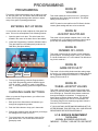
OWNERS AND SERVICE MANUAL
INNOVATIVE CONCEPTS IN ENTERTAINMENT INC.
10123 MAIN STREET, CLARENCE, NY 14031
SERVICE: 1-716-759-0360
FAX: 1-716-759-0884
E-MAIL: [email protected]
WEBSITE: www.icegame.com
1
TABLE OF CONTENTS
INTRODUCTION…………………….…………………..PAGE 3
•
•
GAME FEATURES
GAME PLAY
PROGRAMMING……………....…………………...…...PAGE 4 - 5
•
•
•
ENTERING SET-UP MODE
CHANGING GAME SETTINGS
PROGRAMMING MODES
QUICK TROUBLESHOOTING…..………………..……PAGE 6
MAINTENANCE & TROUBLESHOOTING...……........PAGE 7 - 11
•
•
•
•
OPERATIONAL BACKGROUND
MECHANICAL REPAIR
MECHANICAL MAINTENANCE
ELECTRONIC & ELECTRICAL REPAIR
PARTS LISTING………………………………………....PAGE 12
SCHEMATICS…………………………………………...PAGE 13 - 14
WARRANTY INFORMATION…………………………..PAGE 15 - 16
ICEDOC SX9001
REVISION D
11-01-07
2
INTRODUCTION
GAME PLAY
GAME FEATURES
BREAK THE BANK™ is an electronic coin operated
amusement game designed to be played by one or two
players.
BREAK THE BANK™ is a new and exciting “Coin Roll
Down” game. The unique shape of the game makes this
game stand out from the others. Revolving lights on the
target playfields add to the attraction. The front “Bank
Vault” scene adds a bit of cartoon like humor to the game.
BREAK THE BANK™ is a game similar to the traditional
coin roll down games already on the market. However, we
have made this an even more exciting game. The object
of the game is to break into the bank’s vault, and retrieve
the “loot”.
BREAK THE BANK™ incorporates two separate coin roll
down chutes that allow the game to be played by two
players simultaneously. The whimsical audio game theme
along with verbal comments from potential “bank robbers”
amuse players as the game progresses.
The colorful cabinet decals, lighting and attractive “Marble
Like” bank front are key features in attracting customers.
The top and sides of the playfield are enclosed by glass
panels, making game play visible, not only to the players,
but also to potential players watching the game.
As each coin is rolled down the chute, the player tries to
“time” the coin, so that it stops the revolving light on the
“BONUS” wedge on the wheel. When a coin stops the
revolving light on the “BONUS” wedge on the wheel, the
player is awarded 500 tickets. When a coin stops the revolving light on any other value on the wheel, that number
of tickets is awarded to the player.
The game cabinetry is a unique plywood construction with
a special overlay for a superior finish. All of the cabinet
panels interlock together, are reinforced with cleats and
are glued together to produce a strong cabinet that can
handle abuse.
When the “BONUS” wedge on the wheel is lit, a bonus of
500 tickets is awarded, indicating that the burglar “Broke
the Bank”. On the front display of the game, the bank
vault doors open and a siren goes off, indicating that
someone has “Broke the Bank”.
After the 500 tickets are paid out, the bank vault doors
close and a new game starts.
Loading tickets is a snap, with our easy pivot out door.
This feature drastically reduces the time needed to load
tickets, as well as making it much to service ticket jams or
the dispenser.
When the game is played by two people, the game play
stays the same. The only difference is that two players
compete against each other to see who will win the 500
ticket bonus.
The single center door makes emptying the cash box easier. Coins from both side of the game collect into one
cash box, which can be pulled out and easily emptied.
The use of long life fluorescent and incandescent lighting
provides for lower game maintenance, and greatly adds
to the lively appearance of the game.
NOTE:
THIS GAME IS INTENDED FOR INDOOR USE ONLY.
ON THE BACK PANEL OF THE GAME: WARNING:
SHOCK HAZARD - DO NOT OPEN. REFER SERVICING TO SERVICE PERSONNEL.
3
PROGRAMMING
MODE #1
VOLUME
PROGRAMMING
This section will discuss subjects such as setting up credits, time per game, etc. The section below will show how
to enter into the programming mode and how to adjust
many of the game’s operating parameters.
This mode adjusts the volume from 0 to 5, 0 being the
highest level and 5 being the lowest level. The default
setting for this mode is 3.
NOTE: If power is removed from the PC Board, all other
custom game settings will have to be re-entered.
ENTERING SET-UP MODE
MODE #2
JACKPOT MULTIPLIER
You must enter set-up mode to adjust all of the game features. This can be accomplished in the following manner:
1. Open the game’s coin door. This is the lower door
located in the center of the lower front of the cabinet.
This mode is for the jackpot multiplier from 1 to 20, and
multiplies by 25. (e.g. setting this mode to 8 gives a jackpot of 200) The default setting for this mode is 20.
2. Locate the Programming / Advance & Select buttons.
They are located on the inside panel just above the
Cash Box. (See photo below)
MODE #3
NUMBER OF LOCKS
This mode is used to set the number of locks needed to
get the jackpot. The setting range is from 1 to 4, where 4
is 4 locks needed and 1 is 1 lock needed. The default setting for this mode is 1.
MODE #4
GAME DIFFICULTY
PROGRAM
BUTTON
ADVANCE
BUTTON
This mode is for the ability window and the setting range
is from 0 to 14, 0 being the easiest and 14 being the hardest. Suggested setting for this mode is 10. The default
setting for this mode is 13.
SELECT
BUTTON
3. To enter programming, press the Program button
once. Each programming mode is identified by the
“LED lit” (mode 1, 1st LED lit, mode 2, 2nd LED lit;
etc.). To exit programming, press the Program button
once.
MODE #5
WHEEL JACKPOT VALUES
This mode is used to set the values for the wheel ticket
values. To enter this mode, press the Select button until
all 4 LEDs light up. Press the Select button to advance
through the wedges on the wheel. To change any of
these values, press the Advance button. The “BONUS”
value setting range is from 0 to 50, in increments of 5.
The setting range for the remaining ring wheel values is
from 0 to 9 in increments of 1.
CHANGING GAME SETTINGS
When you press the Program button, you will be in the
programming mode.
1. Each push of the Select button will advance you
through the programming modes.
IF YOU HAVE ANY QUESTIONS REGARDING SET-UP
AFTER READING THIS SECTION, CALL OUR SERVICE
DEPARTMENT BEFORE PROCEEDING AT:
2. Push the Select button to keep you in that mode.
3. Pushing the Advance button will advance you through
the settings for the mode you are in.
I.C.E. SERVICE DEPARTMENT
4. To exit and save your new settings, press the Program button once. You will now be in the normal
game play mode.
716-759-0360
NORMAL BUSINESS HOURS ARE:
MONDAY – FRIDAY, 9:00 AM TO 6:00 PM EST
4
PROGRAMMING
5. Insert your coin or token of choice.
PROGRAMMING
This section will discuss setting up the coin selectors. In
order for the coin selectors to work properly, a “sample” of
the coin or token that will be used for playing the game,
must be placed in the optical comparator of each coin
selector.
To accomplish this task, please perform the following:
1. Remove the rounded cover on the front of the game.
To remove the cover, open the game’s coin door.
This is the lower door located in the center of the
lower front of the cabinet.
2. Reach up underneath the cover and release the 2
latches that secure the cover to the game. (see photo
below) Remove the cover.
6. Release the coin sensor holder. Be sure that the coin
or token is properly seated.
7. Test the coin selector before replacing the front cover.
If the coin selector does not recognize the coin, or
allows coins other than the “compared” coin, a coin
sensitivity adjustment can be made.
3. Determine the type of coin or token that will be used
to play the game.
4. Lift up the coin sensor holder.
8. Locate the coin sensitively adjustment dial on the rear
of the unit. To increase sensitivity, turn the dial
counter-clockwise. To decrease sensitivity, turn the
dial clock-wise. (see photo below)
COIN SENSITIVITY
ADJUSTMENT DIAL
5
QUICK TROUBLESHOOTING
PROBLEM
NO POWER
GAME WILL NOT TAKE COINS /
TOKENS
COINS DO NOT SCORE POINTS
GAME HAS NO SOUND
PROBABLE CAUSE
BAD FUSE AT POWER MODULE
GAME UNPLUGGED
TRIPPED CIRCUIT BREAKER
DAMAGED POWER CORD
INSPECT MAIN FUSES
CHECK POWER CORD
CHECK BREAKER BOX
REPLACE CORD
NO COIN / TOKEN IN COIN COMPARITOR
BAD HARNESSING OR CONNECTOR
BAD MAIN P.C. BOARD
BAD COIN SENSOR
BAD SPEAKER
VOLUME LEVEL SET INCORRECTLY
BROKEN “O” RING
INSERT COIN / TOKEN BEING USED
CHECK AND REPAIR
REPAIR OR REPLACE
REPLACE COIN SENSOR
REPLACE SPEAKER(S)
CHECK SERVICE MANUAL FOR
VOLUME SETTING PROCEDURES
CHECK AND REPAIR
CHECK, REPAIR OR REPLACE AS
NECESSARY.
CHECK AND REPAIR
REPAIR OR REPLACE
ADD TICKETS
CHECK, REPAIR OR REPLACE AS
NECESSARY
CLEAN SENSOR
CHECK, REPAIR OR REPLACE AS
NECESSARY
REPLACE “O” RING
STATIC ELECTRICITY
RESET POWER TO GAME
BAD HARNESSING OR CONNECTOR
BAD MAIN P.C. BOARD
TICKET DISPENSER DOES NOT
WORK OR WORKS
IMPROPERLY
VAULT DOORS DO NOT OPEN
WHEN JACKPOT IS WON
GAME LOSES SOUND DURING
GAME PLAY
SOLUTION
BAD HARNESSING
BAD TICKET DISPENSER
DISPENSER OUT OF TICKETS
BAD MAIN P.C. BOARD
OPTICAL SENSOR ON DISPENSER DIRTY
BAD MOTOR
6
MAINTENANCE & TROUBLESHOOTING
FRONT DISPLAY LIGHT
MECHANICAL REPAIR
•
Remove the rear panel from the game. Locate the
PL-L lamp and remove the clips that retains the lamp.
Press the red button by the end of the bulb that plugs
in and lift the bulb out. Replace with new bulb. Replace clip.
•
REPLACEMENT BULB: 8312
IMPORTANT: USE ONLY ICE REPLACEMENT PARTS
WHEN SERVICING YOUR GAME. USING NON-ICE
APPROVED PARTS COULD VOID YOUR WARRANTY,
AND COULD CAUSE SERIOUS DAMAGE TO THE
GAME OR INJURY TO OTHERS.
IF YOU HAVE ANY QUESTIONS REGARDING REPAIR
AFTER READING THIS SECTION, CALL OUR SERVICE
DEPARTMENT BEFORE PROCEEDING AT:
PLL LAMP LOCATED
BEHIND PC BOARD
I.C.E. SERVICE DEPARTMENT
716-759-0360
NORMAL BUSINESS HOURS ARE:
MONDAY – FRIDAY, 9:00 AM TO 6:00 PM EST
LIGHT BULB REPLACEMENT
WARNING: TURN OFF THE GAME POWER
BEFORE REPLACING LIGHT BULBS
“BREAK THE BANK” MARQUEE LIGHTS
PRIZE WHEEL LIGHTS
•
Remove the rear panel from the game. Locate the PC
Board where the light bulb is not working. Remove
the PC Board by unscrewing the white hexagon spacers that secure the PC Board to the game. Replace
the light bulb. Re-attach the PC Board to the game.
•
REPLACEMENT BULB: 2005
•
Remove the “Bank Front” cover from the game by
removing the 8 screws that attach the cover to the
game. Remove the retaining clips from the PL-L fluorescent bulbs. Press the red button by the end of the
bulb that plugs in and lift the bulb out. Replace with
new bulb.
•
REPLACEMENT BULB: 8312
BANK GUARD SHADOW LIGHTS
•
Remove the rear panel from the game. Unscrew the
“Coin Art” panel and remove from game. Locate the
burned out bulb and replace.
•
REPLACEMENT BULB: 2005
SEE PHOTO ON NEXT PAGE
7
MAINTENANCE & TROUBLESHOOTING
CLEANING
Regular cleaning of the game will keep it looking
new and greatly enhance its appeal.
Clean the glass portions of your BREAK THE
BANK™ with a standard window cleaner such as
Windex®.
Clean the cabinet sides with a good cleaner such as
Fantastik® or Formula 409® and a soft rag. A mild
soapy solution can also be used.
NOTE: DO NOT USE ALCOHOL, THINNERS OF
ANY KIND, OR PINBALL PLAY FIELD CLEANERS
ON ANY OF THE CABINET SURFACES.
ESPECIALLY THE DECALS.
STROBE LIGHT
•
•
Remove the rear panel from the game. Unscrew the
Strobe light, unplug and remove from game. Replace
the entire strobe light unit.
Never spray cleaner directly on surface of game. Spray
cleaner onto rag and wipe clean.
REPLACEMENT LIGHT: SX2535
BEACON LIGHT
•
Remove the 3 screws that attach the cover to the light
base. Replace bulb.
•
REPLACEMENT BULB: 2798
STOPLIGHT FLASH BULBS
•
See STOPLIGHT OPTO SENSOR REPLACEMENT
8
MAINTENANCE & TROUBLESHOOTING
FUSES
ELECTRONIC AND
ELECTRICAL REPAIR
Fuses are the first items that should be checked when the
game is inoperable or works incorrectly. There are 5
fuses in the game.
The following section will describe repair procedures and
trouble shooting hints for the game electronics.
One fuse is located in the Power Mod which is located in
the lower left side in the rear of the cabinet.
Please read the section “Operational Background” in the
beginning of Maintenance and Trouble Shooting to get a
good understanding of the game’s basic operating parameters.
To check or service the fuse, FIRST REMOVE THE
POWER CORD. FAILURE TO DO SO COULD RESULT
IN SERIOUS INJURY OR DEATH. Using a small flat
blade screwdriver, pry down the fuse block cover. Remove the fuse block from the power mod. Pull the fuse
from the fuse block and test the fuses. Be sure to replace
the fuses with the same type and value.
WARNING: EXERCISE CAUTION WHENEVER WORKING WITH ELECTRONICS, THEY CAN BE VERY SUSCEPTIBLE TO DAMAGE FROM SHORT CIRCUITING,
OR PHYSICAL ABUSE. ALWAYS UNPLUG THE GAME
WHEN WORKING ON HIGH VOLTAGE AREAS OF THE
GAME, SUCH AS THE TRANSFORMER.
USE EXTREME CAUTION WHEN USING VOLTMETERS TO DO CIRCUIT CHECKS IF THE GAME POWER
HAS BEEN LEFT ON.
FUSE
ALWAYS REMOVE THE BATTERY BACK-UP POWER
WHEN WORKING ON THE GAME. THIS IS NECESSARY AS SOME CIRCUITS ARE CONSTANTLY UNDER POWER FROM THE BATTERY.
WHEN USING A VOLTMETER, BE SURE IS SET TO
THE CORRECT VOLTAGE OR RESISTANCE RANGE
BEFORE USING. THIS CAN PREVENT POSSIBLE
DAMAGE TO THE PC BOARD OR MISDIAGNOSIS.
ALWAYS REMOVE POWER TO THE GAME WHEN
PLUGGING OR UNPLUGGING PC BOARDS.
IT IS NECESSARY TO USE ICE REPLACEMENT
PARTS TO CONTINUE WARRANTY COVERAGE. USE
OF NON-ICE APPROVED PARTS WILL NOT ONLY
VOID YOUR WARRANTY, BUT COULD CAUSE SERIOUS HARM TO THE GAME, OR CAUSE SERIOUS
BODILY INJURY.
Three fuses are located on the Power Supply PC Board,
and one fuse is located on the AC Power PC Board. Using a small flat blade screwdriver, pry the fuse from the
fuse holder. Remove the fuse from the fuse holder and
test each fuse as required. the fuses. Be sure to replace
the fuses with the same type and value.
IF YOU HAVE ANY QUESTIONS REGARDING REPAIR
AFTER READING THIS SECTION, CALL OUR SERVICE
DEPARTMENT BEFORE PROCEEDING AT:
I.C.E. SERVICE DEPARTMENT
716-759-0360
NORMAL BUSINESS HOURS ARE:
MONDAY – FRIDAY, 9:00 AM TO 6:00 PM EST
9
MAINTENANCE & TROUBLESHOOTING
BALLAST
•
•
Remove the rear panel from the game. Unscrew the
ballast and unplug the wire harness. Replace the ballast “.
•
Remove the Opto Sensor PC Board by unscrewing
the 2 white spacers. Replace the Opto Sensor PC
Board and reassemble in reverse order.
•
REPLACEMENT OPTO SENSOR PC BOARD:
RB2009AX
REPLACEMENT BALLAST: SX8449X
VAULT DOOR SWITCHES
•
Remove the rear panel from the game. Unplug the
wire harness from the switch. Unscrew the switches
and replace.
•
REPLACEMENT SWITCH: 211
STOPLIGHT OPTO SENSOR
•
Remove the rear panel from the game. Remove the
“coin chute elbow” from the score wheel panel, to replace the Opto sensor that is not working.
VAULT DOOR “O” RING
•
Unplug the harness from the Opto Sensor PC Board.
Remove the 2 screws that attach the sensor bracket
to the wheel panel.
10
•
Remove the rear panel from the game. Cut the 2 wire
ties that secure the “O” ring to the vault doors.
(NOTE: one vault door is attached to the “O” ring from
one side of the “O” ring and the other vault door is
attached to the other side of the “O” ring. After the “O”
ring is replaced, the vault doors MUST be attached in
the same manner) Remove the “O” ring and replace.
Re-attach the “O” ring to the vault doors with new wire
ties.
•
REPLACEMENT “O” RING: SX4001
MAINTENANCE & TROUBLESHOOTING
VAULT DOOR MOTOR
•
Remove the rear panel from the game. Locate the
motor in the upper left side of the game. Remove the
“O” ring from the pulley on the motor. Unscrew the 2
carriage bolts and remove the motor. Unplug the harness from the motor.
•
Remove the pulley and the mounting plate from the
motor. Replace the motor and reassemble in reverse
order.
•
REPLACEMENT MOTOR: CS2008X
TICKET DISPENSER
Refer to the supplied service manual for all information
other than software settings.
OVERVIEW
IF YOU HAVE ANY QUESTIONS REGARDING REPAIR
AFTER READING THIS SECTION, CALL OUR SERVICE
DEPARTMENT BEFORE PROCEEDING AT:
I.C.E. SERVICE DEPARTMENT
716-759-0360
NORMAL BUSINESS HOURS ARE:
MONDAY – FRIDAY, 9:00 AM TO 6:00 PM EST
11
PARTS LISTINGS
MECHANICAL PARTS
211
2790
2798
8312
8395
AR2130X
BW2017
BW2018
FP2007
HH5005
HR1019
SX2535
SX4001
TT5001
TX2007X
Low Ticket Micro Switch
Beacon Light
Bulb, 12V, 20W
Bulb, PL-L
Bulb #192
2D Bulb Socket Assembly
Light Clip Base
Light Clip
Speaker, 4” Round
Ticket Dispenser
Leveler Foot - White
Strobe, Small Red
O-Ring Belt
Coin Mech (Electronic Roll Down Acceptor)
Power Mod
ELECTRICAL & ELECTRONIC
PARTS
CA2008WX
SX8449X
RB2009AX
SX2034X
SX2035X
WS2032X
Motor
Ballast Assembly (WH-5)
Opto PC Board
Main PC Board
AC PC Board
Display PC Board
GRAPHICS & DECALS
SX7012
SX7050
SX7051
Decal - Instructions
Decal - Left Side
Decal - Right Side
12
13
14
Warranty
I.C.E warrants all components in the BREAK THE BANK™ game to be free of defects in materials and workmanship for a period of ninety days from the date of purchase.
This warranty does not cover items damaged due to normal wear and tear,
subjected to abuse, improperly assembled by the end user, modified, repaired, or
operated in a fashion other than that described in the service manual.
If your BREAK THE BANK™ game fails to conform to the above-mentioned warranty, I.C.E.'s sole responsibility shall be at its option to repair or replace any defective component with a new or remanufactured component of equal to or greater
O.E.M. specification.
I.C.E. will assume no liability whatsoever, for costs associated with labor to replace
defective parts, or travel time associated therein.
I.C.E.'s obligation will be to ship free of charge, replacement parts by domestic
U.P.S. Ground, U.S. mail, or other comparable shipping means. Any express mail
or overnight shipping expense is at the cost of the purchaser.
Products will be covered under warranty only when:
·
The serial number of the game with the defective parts is given.
·
The serial number of the defective part, if applicable, is given.
·
Defective parts are returned to I.C.E., shipping pre-paid, in a timely fashion, if
requested by I.C.E.
·
A copy of the sales receipt is available as proof of purchase upon request of
I.C.E.
I.C.E. distributors are independent, privately owned and operated. In their
judgment, they may sell parts or accessories other than those manufactured by
I.C.E. We cannot be responsible for the quality, suitability, or safety of any nonI.C.E. part, or any modification, including labor, which is performed by such a distributor.
15
WARRANTY
ICE Inc warrants that all of its products will be free from defects in material and workmanship.
When placing a warranty request, please be prepared to provide the following information:
·
·
·
Serial Number of Game or Bill of Sale
Machine Type
A Detailed Description of the Equipment Fault Symptoms
ICE product, including Cromptons, Sam’s Billiards, Uniana and Bell Fruit is warranted as follows:
·
⋅
·
·
·
·
180 days on the Main PCB and Computers
180 days on Motors
90 days on all other components (i.e. DBV’s, Ticket Dispensers, etc)
30 days on repaired items
3 years on all Crane Harnessing
9 Months on Printers
ICE Inc shall not be obligated to furnish a warranty request under the following conditions:
·
·
·
Equipment has been subjected to unwarranted stress through abuse or neglect
Equipment has been damaged as a result of arbitrary repair/modification attempts
Equipment that has failed through normal wear and tear
ICE Inc will assume no liability whatsoever for costs associated with labor to replace defective parts or
travel time associated therein.
All defective warranty covered components will be replaced with new or factory refurbished components
equal to OEM specifications. ICE Inc will cover all domestic UPS ground, or comparable shipping means,
freight costs during the warranty period. Expedited shipments are available for an additional charge.
Defective parts are returned to ICE Inc, at the customer’s expense, in a timely fashion.
ICE distributors are independent, privately owned and operated. In their judgment, they may sell parts
and/or accessories other than those manufactured by ICE Inc. We cannot be responsible for the quality,
suitability or safety of any non-ICE part, modification (including labor) that is performed by such a
distributor.
I.C.E. Parts/Service Dept.
Innovative Concepts in Entertainment
10123 Main St.
Clarence, NY 14031
Phone #: (716) - 759 – 0360
Fax #: (716) – 759 – 0884
16