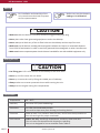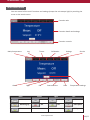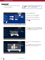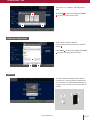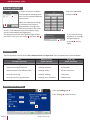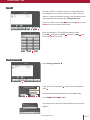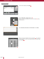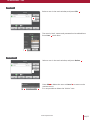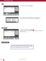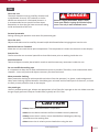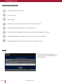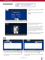
1
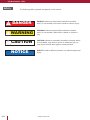
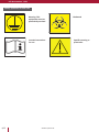
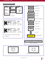
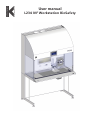
User manual L234 IVF Workstation BioSafety IVF Workstation - L234 2/57 www.k-systems.dk IVF Workstation - L234 Dear Customer Congratulations with your new K-SYSTEMS product. Before installation, please check the product for obvious damage, which may have happened during transport. K-SYSTEMS encourage you to register your product on our homepage. This will enable us to inform you about important updates and safety issues directly. Please go to http://www.k-systems.dk/product-registration.html for registration For further information on installation and validation of your new product - Please read and follow carefully the instructions in the User Manual. If you need further assistance, please contact your local K-SYSTEMS supplier or K-SYSTEMS directly. Best regards, Kivex Biotec Ltd. - K-SYSTEMS www.k-systems.dk 3/57 IVF Workstation - L234 Content Safety. . . . . . . . . . . . . . . . . . . . . . . . . . . . . . . . . . . . . . . . . . . . . . . . . . . . . . . . 6 General safety . . . . . . . . . . . . . . . . . . . . . . . . . . . . . . . . . . . . . . . . . . . . . 7 Safety symbols on the unit. . . . . . . . . . . . . . . . . . . . . . . . . . . . . . . . . . . 8 Other symbols on the unit . . . . . . . . . . . . . . . . . . . . . . . . . . . . . . . . . . . 9 Intended use . . . . . . . . . . . . . . . . . . . . . . . . . . . . . . . . . . . . . . . . . . . . . . . . . . 10 Operating principles. . . . . . . . . . . . . . . . . . . . . . . . . . . . . . . . . . . . . . . . 10 Safe handling of embryos and blastocysts. . . . . . . . . . . . . . . . . . . . . . . . 11 Characteristics . . . . . . . . . . . . . . . . . . . . . . . . . . . . . . . . . . . . . . . . . . . . 11 Overview . . . . . . . . . . . . . . . . . . . . . . . . . . . . . . . . . . . . . . . . . . . . . . . . . . . . . 12 Airflow and filter . . . . . . . . . . . . . . . . . . . . . . . . . . . . . . . . . . . . . . . . . . 14 Touch screen . . . . . . . . . . . . . . . . . . . . . . . . . . . . . . . . . . . . . . . . . . . . . 14 Microscope light. . . . . . . . . . . . . . . . . . . . . . . . . . . . . . . . . . . . . . . . . . . 14 AluHeat Technology . . . . . . . . . . . . . . . . . . . . . . . . . . . . . . . . . . . . . . . . 14 Monitor . . . . . . . . . . . . . . . . . . . . . . . . . . . . . . . . . . . . . . . . . . . . . . . . . 14 Gassing and humidification system – GH01. . . . . . . . . . . . . . . . . . . . . . . 14 Tray lid . . . . . . . . . . . . . . . . . . . . . . . . . . . . . . . . . . . . . . . . . . . . . . . . . . 14 Connections panel. . . . . . . . . . . . . . . . . . . . . . . . . . . . . . . . . . . . . . . . . . 15 Lock . . . . . . . . . . . . . . . . . . . . . . . . . . . . . . . . . . . . . . . . . . . . . . . . . . . . 16 Network connection. . . . . . . . . . . . . . . . . . . . . . . . . . . . . . . . . . . . . . . . 16 Gas system connector. . . . . . . . . . . . . . . . . . . . . . . . . . . . . . . . . . . . . . . 16 Alarm output . . . . . . . . . . . . . . . . . . . . . . . . . . . . . . . . . . . . . . . . . . . . . 16 Backside of unit. . . . . . . . . . . . . . . . . . . . . . . . . . . . . . . . . . . . . . . . . . . . 17 Setup. . . . . . . . . . . . . . . . . . . . . . . . . . . . . . . . . . . . . . . . . . . . . . . . . . . . . . . . . 18 Moving the unit . . . . . . . . . . . . . . . . . . . . . . . . . . . . . . . . . . . . . . . . . . . 18 Environment. . . . . . . . . . . . . . . . . . . . . . . . . . . . . . . . . . . . . . . . . . . . . . 18 Touch screen menu. . . . . . . . . . . . . . . . . . . . . . . . . . . . . . . . . . . . . . . . . 19 Time settings . . . . . . . . . . . . . . . . . . . . . . . . . . . . . . . . . . . . . . . . . . . . . . 20 Ethernet configuration . . . . . . . . . . . . . . . . . . . . . . . . . . . . . . . . . . . . . . 21 Unit lock. . . . . . . . . . . . . . . . . . . . . . . . . . . . . . . . . . . . . . . . . . . . . . . . . 21 Calibration. . . . . . . . . . . . . . . . . . . . . . . . . . . . . . . . . . . . . . . . . . . . . . . . . . . . 22 Heat zones and temperature measure points. . . . . . . . . . . . . . . . . . . . . 22 Adjustment procedure . . . . . . . . . . . . . . . . . . . . . . . . . . . . . . . . . . . . . . 23 Access control. . . . . . . . . . . . . . . . . . . . . . . . . . . . . . . . . . . . . . . . . . . . . . . . . 26 Access levels. . . . . . . . . . . . . . . . . . . . . . . . . . . . . . . . . . . . . . . . . . . . . . 26 Access control settings . . . . . . . . . . . . . . . . . . . . . . . . . . . . . . . . . . . . . . 26 Login . . . . . . . . . . . . . . . . . . . . . . . . . . . . . . . . . . . . . . . . . . . . . . . . . . . 27 Change password. . . . . . . . . . . . . . . . . . . . . . . . . . . . . . . . . . . . . . . . . . 27 Create new user. . . . . . . . . . . . . . . . . . . . . . . . . . . . . . . . . . . . . . . . . . . 28 Edit user. . . . . . . . . . . . . . . . . . . . . . . . . . . . . . . . . . . . . . . . . . . . . . . . . 29 Delete user. . . . . . . . . . . . . . . . . . . . . . . . . . . . . . . . . . . . . . . . . . . . . . . 29 Log. . . . . . . . . . . . . . . . . . . . . . . . . . . . . . . . . . . . . . . . . . . . . . . . . . . . . 30 Logging out. . . . . . . . . . . . . . . . . . . . . . . . . . . . . . . . . . . . . . . . . . . . . . . 30 Lost password. . . . . . . . . . . . . . . . . . . . . . . . . . . . . . . . . . . . . . . . . . . . . . 30 Use . . . . . . . . . . . . . . . . . . . . . . . . . . . . . . . . . . . . . . . . . . . . . . . . . . . . . . . . . . 31 General workflow overview . . . . . . . . . . . . . . . . . . . . . . . . . . . . . . . . . . 32 Fans . . . . . . . . . . . . . . . . . . . . . . . . . . . . . . . . . . . . . . . . . . . . . . . . . . . . 32 Temperature setpoint. . . . . . . . . . . . . . . . . . . . . . . . . . . . . . . . . . . . . . . 33 Logs . . . . . . . . . . . . . . . . . . . . . . . . . . . . . . . . . . . . . . . . . . . . . . . . . . . . 33 Timers schedule. . . . . . . . . . . . . . . . . . . . . . . . . . . . . . . . . . . . . . . . . . . 34 Alarm. . . . . . . . . . . . . . . . . . . . . . . . . . . . . . . . . . . . . . . . . . . . . . . . . . . 35 Microscope light. . . . . . . . . . . . . . . . . . . . . . . . . . . . . . . . . . . . . . . . . . . . 36 Microscope light. . . . . . . . . . . . . . . . . . . . . . . . . . . . . . . . . . . . . . . . . . . 37 Filters. . . . . . . . . . . . . . . . . . . . . . . . . . . . . . . . . . . . . . . . . . . . . . . . . . . 37 4/57 www.k-systems.dk IVF Workstation - L234 Monitor . . . . . . . . . . . . . . . . . . . . . . . . . . . . . . . . . . . . . . . . . . . . . . . . . . . . . . 38 On-screen display (OSD) menu. . . . . . . . . . . . . . . . . . . . . . . . . . . . . . . . 38 Picture . . . . . . . . . . . . . . . . . . . . . . . . . . . . . . . . . . . . . . . . . . . . . . . . . . 39 Position . . . . . . . . . . . . . . . . . . . . . . . . . . . . . . . . . . . . . . . . . . . . . . . . . 39 Clock and phase. . . . . . . . . . . . . . . . . . . . . . . . . . . . . . . . . . . . . . . . . . . 39 Color temperature . . . . . . . . . . . . . . . . . . . . . . . . . . . . . . . . . . . . . . . . . 39 Management . . . . . . . . . . . . . . . . . . . . . . . . . . . . . . . . . . . . . . . . . . . . . 40 OSD Display . . . . . . . . . . . . . . . . . . . . . . . . . . . . . . . . . . . . . . . . . . . . . . 40 Language . . . . . . . . . . . . . . . . . . . . . . . . . . . . . . . . . . . . . . . . . . . . . . . . 40 Input source. . . . . . . . . . . . . . . . . . . . . . . . . . . . . . . . . . . . . . . . . . . . . . 40 Recall. . . . . . . . . . . . . . . . . . . . . . . . . . . . . . . . . . . . . . . . . . . . . . . . . . . 40 Gas humidifier system GH01. . . . . . . . . . . . . . . . . . . . . . . . . . . . . . . . . . . . . 41 Glass bottle . . . . . . . . . . . . . . . . . . . . . . . . . . . . . . . . . . . . . . . . . . . . . . 42 Tube connections. . . . . . . . . . . . . . . . . . . . . . . . . . . . . . . . . . . . . . . . . . 42 Warming . . . . . . . . . . . . . . . . . . . . . . . . . . . . . . . . . . . . . . . . . . . . . . . . 43 Condensation. . . . . . . . . . . . . . . . . . . . . . . . . . . . . . . . . . . . . . . . . . . . . 43 Gas flow adjustment. . . . . . . . . . . . . . . . . . . . . . . . . . . . . . . . . . . . . . . . 43 Glass incubator hoods. . . . . . . . . . . . . . . . . . . . . . . . . . . . . . . . . . . . . . . 44 Warming blocks for tubes. . . . . . . . . . . . . . . . . . . . . . . . . . . . . . . . . . . . 45 Warming blocks for culture dishes. . . . . . . . . . . . . . . . . . . . . . . . . . . . . 46 Warming blocks for syringes. . . . . . . . . . . . . . . . . . . . . . . . . . . . . . . . . . 47 Warming blocks for media flasks . . . . . . . . . . . . . . . . . . . . . . . . . . . . . . 47 Maintenance. . . . . . . . . . . . . . . . . . . . . . . . . . . . . . . . . . . . . . . . . . . . . . . . . . 48 Daily maintenance . . . . . . . . . . . . . . . . . . . . . . . . . . . . . . . . . . . . . . . . . 48 Weekly maintenance . . . . . . . . . . . . . . . . . . . . . . . . . . . . . . . . . . . . . . . 48 Annually maintenance . . . . . . . . . . . . . . . . . . . . . . . . . . . . . . . . . . . . . . 48 Additional maintenance. . . . . . . . . . . . . . . . . . . . . . . . . . . . . . . . . . . . . 48 Service information . . . . . . . . . . . . . . . . . . . . . . . . . . . . . . . . . . . . . . . . . . . . 49 Fuses. . . . . . . . . . . . . . . . . . . . . . . . . . . . . . . . . . . . . . . . . . . . . . . . . . . . . 49 Replacing interior light . . . . . . . . . . . . . . . . . . . . . . . . . . . . . . . . . . . . . . 50 Troubleshooting . . . . . . . . . . . . . . . . . . . . . . . . . . . . . . . . . . . . . . . . . . . . . . . 51 Technical data . . . . . . . . . . . . . . . . . . . . . . . . . . . . . . . . . . . . . . . . . . . . . . . . . 53 Disposal . . . . . . . . . . . . . . . . . . . . . . . . . . . . . . . . . . . . . . . . . . . . . . . . . . 56 Recyclable components . . . . . . . . . . . . . . . . . . . . . . . . . . . . . . . . . . . . . 56 Warranty and product liability . . . . . . . . . . . . . . . . . . . . . . . . . . . . . . . . . . . 57 Models covered in this manual: Model L234 Copyright K-SYSTEMS Kivex Biotec. This manual contains information protected by copyright law. No part of this manual may be reproduced or transmitted in any form without prior written permission from the copyright holder. This manual is subject to change without further notice. Version 1.00 10/2013 Original instructions www.k-systems.dk 5/57 IVF Workstation - L234 Safety The following safety symbols may appear in this manual: DANGER 6/57 DANGER indicates an imminently hazardous situation which, if not avoided, will result in death or serious injury. WARNING WARNING indicates a potentially hazardous situation which, if not avoided, could result in death or serious injury. CAUTION CAUTION indicates a potentially hazardous situation which, if not avoided, may result in minor or moderate injury. It may also be used to alert against unsafe practices. NOTICE NOTICE is used to address practices not related to personal injury. www.k-systems.dk IVF Workstation - L234 General safety WARNING •Use only suitable premix gas. Use of other gasses could result in serious injury, depending on the gas connected. CAUTION •Read and understand the manual completely before use. Keep the manual close to the unit. •Do not use the workstation if the outer packaging is damaged. •Never use and handle this unit in other ways than specified in this manual. Your safety may be at risk and the unit may be damaged. •Never try to lift or move the unit alone. •Protect the power cord from being walked on or pinched. •Always use a grounding-type plug. If the plug does not fit into your outlet, consult an electrician for replacement of the outlet. •Unplug the unit during lightning storms or when unused for a long period of time. •Always wear protective shoes while moving the unit. •Do not perform repairs, disassembles, assembly operations, extensions, re-adjustments or modifications on this unit. This must be carried out by K-SYSTEMS or by persons authorized by K-SYSTEMS only. •Never use the device without the front windows correctly attached. •Always have the tray closed when using the unit. •Never use the workstation without an original K-SYSTEMS HEPA filter. •Reduce the risk of fire or electric shock. This equipment should not be exposed to rain or moisture and large objects filled with liquids (>500ml). •Do not expose the filter to liquids. Change filters that have been exposed to liquids. •Always wear full protective equipment and clothing i.e. gloves, masks and general clean room clothing. NOTICE •Do not change the calibration value yourself. This should be done only by an authorized K-SYSTEMS service technician, as described in the service manual. •Do not use the workstation at room temperatures exceeding 30° C. Room temperature above 30° C will compromise the fertilization process. The relative humidity must not exceed 75% (non-condensing). www.k-systems.dk 7/57 IVF Workstation - L234 Safety symbols on the unit Warning: This equipment must be protectively earthed Consult instructions for use 8/57 www.k-systems.dk Biohazard Specific warning or precaution IVF Workstation - L234 Other symbols on the unit Aux, light T5.0AH, 250V Fans T4.0AH 250V Controller T10.0AH, 250V Outlets T1.0AH, 250V AUX, monitor T1.0AH, 250V Key label LOCK Right table T10.0AH, 250V Left table T10.0AH, 250V Fuse labels MAIN SWITCH Switch label MAINS Mains label GAS INLET (MAX 1 BAR) Gas label GAS OUTLET Gas label CAUTION SAMPLE PORT KEEP SILICONE CAP ON ETHERNET GND P Ma Label for sample port Ethernet label HDMI HDMI label ALARM OUTPUT Alarm label GND WARRANTY VOID IF BROKEN O Main product label, K-Systems brand logo and address. On / Off I LOCK WARNING USE ONLY SUITABLE PREMIX GAS MAIN SWITCH MAINS GAS INLET (MAX 1 BAR) Warranty label GND VIDEO + Gas warning label 12V DC GAS OUTLET Power inlet Max. 500 mA IVF Workstation L234 BioSafety CAUTION SAMPLE PORT KEEP SILICONE CAP ON LOCK Product model label ETHERNET MAIN SWITCH HDMI MAINS GAS INLET (MAX 1 BAR) ALARM OUTPUT GND 12V DC GAS OUTLET Power inlet Max. 500 mA CAUTION SAMPLE PORT KEEP SILICONE CAP ON 12V DC VIDEO + VIDEO - O I WARNING USE ONLY SUITABLE PREMIX GAS ETHERNET HDMI GND WARRANTY VOID IF BROKEN Power inlet for camera Video inlet / power outlet for camera ALARM OUTPUT GND 12V DC WARRANTY VOID IF BROKEN O I www.k-systems.dk 9/57 IVF Workstation - L234 Intended use Intended medical indication / Intended use definition The intended use for the L234 Workstation according to the MDD Article 2 is defined as: The intended use of the L234 IVF Workstations is to establish a single or multiple workplaces with a laminar flow hood supplied with a HEPA filtered gas mixture of atmospheric air and CO2 suitable for manipulations of embryos and blastocysts. Requirements to the operator The L234 IVF Workstation shall be used by personnel trained in using IVF workstations. When using the L234 IVF Workstation operator shall wear full protective equipment and clothing i.e. gloves, masks and general clean room clothing. Operating environment The L234 IVF Workstation is intended to be used at room temperature, in a stand-alone environment, at medical clinics and hospital laboratories under normal working conditions. Intended Patient population No patient is in contact with or treated by this workbench. Intended part of the body or type of tissue applied to or interacted with The type of tissue applied to or interacted with is the human egg fertilized with the sperm. Intended User Profile The user profile is the trained health professional who as a qualified person provide the functions of fertilizing the human egg. Operating principles The L234 Workstations typically works the following way: •the unit is connected, the gas is attached and the unit is turned on •after 30 minutes the unit will be at a constant working temperature and air flow •dishes with eggs and sperm are transferred to the working area, eggs and sperm will not come in physical contact with the workstation •a dish with an egg is placed under the microscope •the egg is fertilized with the sperm •the embryo is removed from the L234 and placed in an incubator •the embryo is repeatedly placed back under the microscope for control 10/57 www.k-systems.dk IVF Workstation - L234 Safe handling of embryos and blastocysts To protect the embryos and blastocysts from particle emission from the operator, he or she must always wear protective equipment and clothing i.e. gloves, masks and general clean room clothing. Special attention should be given to hands and lower parts of the arms, as these are the parts of the operator most likely to emit particles near the product. Minimizing the risk of mix up of eggs and sperm •Never work in the unit with eggs and sperm from more than one pair of donors at the same time. •Always mark the eggs and the sperm with name and journal number/social security number. •Use color code labels. Use one color for one pair of egg and sperm cell to be fertilized. Use another color for another pair of egg and sperm cell to be fertilized. This method further prevent mix up as the operator only fertilizes for instance a red tabled egg with a red tabled sperm cell, and a green labeled egg with a green labeled sperm cell. •Do not use the same workstation or the same room for handling of contaminated (i.e. HIV or Hepatitis) eggs and sperm and non-contaminated eggs and sperm. Always use separate workstations and separate rooms. •Protect the workstations with an emergency power system in case of power failure. Characteristics Significant performance characteristics The K-Systems L234 Workstation are devices for maintaining temperature and clean gas conditions for gametes and/or embryos. The L234 IVF Workstations are designed as a biological safety cabinet to protect both the embryos and the operator. Significant physical characteristics A single aseptic workplace created by the controllable laminar flow (with two HEPA filters) and a recirculation of air flow through HEPA filters (app. 60% recirculation – app. 40% exhaust). The average air speed inside the work area is around 0.30 m/s and the velocity is measured via an anemometer placed inside the work area. The HEPA filter is a H14 grade filter having an efficiency of 99.995% regarding particles size < 0.3μm. Incorporating a warm area together with the option of having humidified premixed gas helps in keeping correct pH-levels, required in various ART techniques. The gas used for these workstations is a suitable premixed gas which ensures a correct pH-level. The idea is to achieve the best possible environment for gametes and embryos during the various procedures. The workstations are prepared for the mounting of up to two stereo microscopes, one on the right hand side and one on the left hand side. The workstation will be operated from a touchscreen module, and it is available with the options of an incorporated external monitor. www.k-systems.dk 11/57 IVF Workstation - L234 Overview ① ② ③ ④ ⑤ Feature 12/57 1 Airflow system 2 Touch screen 3 Heat zones 4 Microscope light unit 5 Tray lid www.k-systems.dk IVF Workstation - L234 HDMI ① ② ③ ④ ⑤ ⑥ Feature 1 Monitor 2 Power outlet 230 VAC / 115 VAC 3 Gas hose connector 4 Power outlet for video camera 5 HDMI connector for monitor 6 Power outlet 230 VAC / 115 VAC External computing devices connected to the Ethernet and HDMI connector of IVF Workstation must only be Limited Power Source and SELV circuit according to the standards IEC/UL 60950-1. www.k-systems.dk 13/57 IVF Workstation - L234 Airflow and filter The airflow keeps particles away from the operator. The air is filtrated through the HEPA filters to ensure it is clean when leaving and circulating the unit. For more information about the airflow and filter, see chapter Use and Maintenance. Touch screen With the exception of the microscope light, all functions and adjustments are accessed via the touch screen. For more information about the touch screen, see chapter Use. Microscope light The microscope light is adjustable. For more information about the microscope light, consult the separate Microscope light units manual. AluHeat Technology The units are equipped with adjustable heat zones. The heat zones vary according to the unit model. The heat zones are marked on the tabletop. For more information about the heating system, see chapter Use and Calibration. Monitor The monitor can be used to show images from the microscope camera, and is suitable for educational purposes. For details about the monitor, see chapter Monitor. Gassing and humidification system – GH01 The unit is prepared for usage of the K-SYSTEMS GH01 gas system. For more information about the gas system, see chapter Gas humidifier system GH01. Tray lid The lid allows access to the tray. 14/57 For more information about the tray lid, see chapter Maintenance. www.k-systems.dk GAS OUTLET IVF Workstation - L234 Power inlet Max. 500 mA CAUTION SAMPLE PORT KEEP SILICONE CAP ON Connections panel ETHERNET HDMI ALARM OUTPUT GND WARRANTY VOID IF BROKEN ① 12 ④ O I ② WARNING USE ONLY SUITABLE PREMIX GAS ③ V ⑥ WARNING THIS EQUIPMENT MUST BE PROTECTIVELY EARTHED # ⑤ VIDEO + Feature 1 Lock 2 Mains connection with fuse 3 Network connection 4 Main switch (I= ON, O= Off) 5 Gas system connector 6 Alarm output www.k-systems.dk 15/57 IVF Workstation - L234 Lock The unit has a lock and a set of keys. It is only possible to switch the unit on when it is unlocked and the key is in place. For more information about the lock, see chapter Use. Network connection RJ45 network connector for optional data logger. For more information about the network connector, consult the Data logger manual. Gas system connector Gas hose connector for optional premix gas system GH01. For more information about the gas system, consult the Gas equipment manual. Alarm output Output for external alarm system (e.g. sms alarm system). 16/57 www.k-systems.dk For more information about the alarm system, contact an authorized K-systems service representative. IVF Workstation - L234 Backside of unit ① ⑤ ② ⑥ ③ ④ # Feature 1 Warning labels (Shock hazard) 2 Left table, controller and auxiliary fuses 3 Fan fuses 4 Light and AUX fuses 5 Right table and outlets fuses 6 Technique hatches www.k-systems.dk 17/57 IVF Workstation - L234 Setup For installation and assembly of the unit, consult an authorized K-systems service representative. Before use, see the chapters Settings and Calibration. CAUTION •Make sure that the device is correctly earthed using grounding-type plug •Never place other heat generating equipment under the tabletop. •Never attempt to block any of the air flow holes on the tabletop and on top of the unit. •Make sure that all devices emitting electromagnetic radiation are kept at a reasonable distance from L234 IVF workstation in order to avoid any potential electromagnetic or other interferences. •Make sure there are separate power circuits that are intended for use with medical equipment only. Moving the unit CAUTION •Use lifting gear. Lift in all 4 corners of the tabletop at the same time. •Never try to lift or move the unit alone. •Never try to move the unit by lifting the middle part of tabletop. •Always make sure to wear protective shoes while moving the unit. •Always use the original casing for transportation. Environment 18/57 Temperature 20 – 30 oC Humidity Less than 75% (non-condensing) Placement On a flat, hard and stable surface. Unit must be kept away from heating and cooling devices Clearance Allow at least 2 cm clearance from the rear, 30 cm from the top and 20 cm from left and right for proper ventilation. Environment Indoor use only. Avoid high temperature, moisture, water and dust This unit must not be exposed to dripping or splashing. This unit is designed for use at altitudes under 2000 m. www.k-systems.dk IVF Workstation - L234 Touch screen menu You can control all the unit’s functions and settings (except the microscope light) by touching the areas on the touch screen. Function tabs Function details and settings Function controls Main/temperature Log Alarm Light Heat Timers Calibration Fan Date and time Alarm Light Settings Heat Service Temperature settings Fan Off Not set Off Off Warming up Set On Half speed On Full speed www.k-systems.dk 19/57 IVF Workstation - L234 Time settings During startup check system time and date, and correct if needed. Several of these settings require login. See Access control. Press the Settings tab 1 . 1 2 To adjust the time press Set time 2 . To adjust the date press Set date 3 . 3 Select 12h or 24h time settings under Format 4 . 4 Select either 12h or 24h time settings, and press Ok 5 to save the setting or Cancel 6 to return to the previous screen. 5 6 Press the + or - buttons 7 to adjust the time. 7 8 20/57 Press Set 8 to save the setting or Cancel 9 to return to the previous screen. 9 www.k-systems.dk IVF Workstation - L234 Press the + or - buttons 10 to adjust the date. Press Set 11 to save the setting or Cancel 12 to return to previous screen. 10 11 12 Ethernet configuration Select usb0, Dhcp or static IP. If you choose static ip, enter the static IP adress 1 . Press Save 2 to save the setting or Cancel 3 to return to the previous screen. 1 2 3 Unit lock The unit cannot be switched on while it is locked. It is only possible to switch the unit on when it is unlocked and the key is in place. Turn the key on the units' side to unlock. www.k-systems.dk 21/57 IVF Workstation - L234 Calibration NOTICE The units can be equipped with different heat zone and heated glass layouts. The temperature calibration procedure for a specific heat zones depends on the heat zone's layout. •Use only thermometer and temperature probe equipment that are specified in the service manual. •Calibration must only be carried out by trained personnel. (i.e., a service technician authorized by K-SYSTEMS). Heat zones and temperature measure points 4 feet unit with 4 heat zones. Right. 1 2 Temperature measure points. Heat zone number. 1 2 Temperature measure point for heated glass. 3 4 4 feet unit with 4 heat zones. Left. 4 3 4 1 3 22/57 2 www.k-systems.dk 2 4 IVF Workstation - L234 Adjustment procedure To calibrate the heat zones, K-Systems recommends that you use the precision thermometer F100 and a Falcon® or Nunc® dish with a PT-100 temperature probe. Alternatively, you can buy a probe from your local K-Systems distributor. Identify your unit's heat zone layout. Refer to the section Heat zones and temperature measure points. Several of these settings require login. See chapter Access control. 1 Turn on the heat zone 1 and the fan 2 . Wait at least 40 minutes for the temperature to stabilize. 2 1 2 36.8 oC 1 3 2 Place the temperature probe on the first calibration point in one of the heat zones. Measure the temperature and write it down. 4 www.k-systems.dk 23/57 IVF Workstation - L234 3 Measure the temperature at the second calibration point in the same heat zone. Write the value down. 1 2 36.2 oC 4 The mean temperature for the heat zone is calculated using the following formula: Temperature 1 + Temperature 2 2 4 3 In the example shown above, the mean temperature would be: 36.8 oC + 36.2 oC = 2 36.5 oC 5 3 Press the Calibration tab 3 on the touch screen. Press the calibration button 4 at the relevant heat zone. 4 6 Adjust the temperature to the same value as the measured mean temperature. The calibration value 5 is shown just beneath the temperature value. Press Save 6 to store the new value. 5 6 24/57 www.k-systems.dk IVF Workstation - L234 7 1 Only one measurement is taken at the calibration point for the center of the heated glass. Calibrate using the measured value directly. 2 36.9 oC 4 3 8 Press the calibration button 7 for the heated glass. 9 Adjust the temperature to the same value as the measured temperature. 7 10 Continue with calibration on all heat zones. Calibration must be performed at least once a year. www.k-systems.dk 25/57 IVF Workstation - L234 Access control 1 Enter your password and press OK 3 . In order to prevent unauthorized changes to setup parameters, the unit provides different access levels. When you attempt to change 2 a parameter that requires authorization, the login window will pop up on the touch screen. If you leave the topic that requires login, you will automatically be logged out. The popup only shows users possessing a valid access level. Press your user name 1 and press OK 2 . 3 4 If you enter a wrong password, a message will be displayed. Press OK 4 and try again. Access levels The unit supports 3 access levels: User, Advanced user and Super user. Their characteristics are shown below: User (no login required) Advanced user (login required) •Switch heat and light on/off Super user (login required) Same as User and Same as Advanced user and •Switch fan on/off/reduced •Change setpoint •Calibration •Move between the different tabs •Change timers •Create new users •See the alarm log •Change settings •Edit users •See the security log and users •Change own password •Delete users Access control settings 1 Press the Settings tab 1 . Press Settings 2 under Security. 2 26/57 www.k-systems.dk IVF Workstation - L234 Login The user “admin” is the only active user upon delivery of the workbench. The admin's password is 1234. The user "admin" cannot be deleted. However, the password is editable and should be changed. See Change Password. 1 Press the "admin" user name 1 and press Login 2 , or press Exit 3 to return to the previous menu. 2 3 Enter the password. The default password is 1234. Press OK 4 to proceed, Cancel 5 to abort or Back 6 to return to the previous menu. 6 5 4 Change password Press Change password 1 . 1 2 3 4 5 Enter the current password 2 . Enter the new password twice 3 . The password must be between 4 and 10 digits long. Press Ok 4 or Cancel 5 to abort. If you don't enter the same password twice, this warning appears www.k-systems.dk 27/57 IVF Workstation - L234 Create new user 1 In the main window, Press New 1 . Select Advanced or Super user level 2 . When you press the buttons for the user's name 3 , a keyboard pops up. 2 3 Enter Surname, First name and User name. Press Next. When pressing the buttons for the password 4 , the numeric keyboard pops up. Enter a password between 4 and 10 digits. Press OK 5 . 4 5 28/57 www.k-systems.dk IVF Workstation - L234 Edit user Select a user in the main window, and press Edit 1 . 1 The security level, names and password can be edited here. Press Save 2 when done. 1 Delete user Select a user in the main window, and press Delete 1 . 1 2 3 Press OK 2 to delete the user or Cancel 3 to return to the previous menu. It is not possible to delete the "admin" user. www.k-systems.dk 29/57 IVF Workstation - L234 Log In the main window press Log 1 . 1 The log shows the last 100 changes including their date, time and user. You can slide the screen up and down. Logging out In the main window press Logout 1 . Super users will be automatically logged out after 5 minutes without activity. 1 Lost password If all super user passwords become lost, please contact your local K-System distributor to acquire a special login that is calculated from the unit's serial number. 30/57 www.k-systems.dk IVF Workstation - L234 Use Clean the unit The work chamber must be carefully cleaned and/ or disinfected. Use only 70% ethanol or similar. NEVER use ammonia or chlorinated cleaners. It is recommended to use special lint-free wipes. Remember to clean the gas hose connector sitting inside and outside of the unit. DANGER Ethanol is highly flammable. Keep it away from open flames. Unplug all electrical equipment. Use only in well-ventilated room. Personal protection During cleaning the operator must wear full protective gear. Clean the tools Objects and tools must be carefully cleaned and/or disinfected before bringing them into the unit. Switch the heat on if needed Allow the unit to reach the set point temperature. The temperature is shown on the touch screen display. Start the fan The fan must be run at normal speed for at least 30 minutes prior to working inside the unit. Avoid movement Tools and objects must be placed within reach to avoid unnecessary movement inside the unit. Do not overfill the working area It is important to keep the air flow undisturbed as much as possible. Therefore, never overload the work chamber - insert only tools and objects necessary for the actual work. Wear protective clothing Wear protective clothing to reduce particle emissions from the operator (i.e. gloves, masks and general clean room clothing). Special attention should be given to hands and the lower parts of the arms, as these are likely to emit particles close to the sample. Use premix gas Use only suitable premix gas. Always use appropriate in-line filters for input gas to the unit. Make sure that the gas supply pressure is kept at a stable level, typically at 0.5-0.7 bar. CAUTION •Always have the lid closed when in operation. •Never use the device without the front windows correctly attached. •Always cover the air velocity sensor head before initiating any cleaning procedure on the working area. •Never cover the air velocity sensor head when using the unit. www.k-systems.dk 31/57 IVF Workstation - L234 General workflow overview ① Insert the key and unlock the unit ② Turn the unit on ③ Attach the gas ④ Wait 30 minutes until the temperature and the air flow is constant ⑤ Transfer dishes with eggs and sperm to the working area ⑥ Place a dish with an egg under the microscope and fertilize the egg with the sperm ⑦ Remove the dish with the embryo from the unit and place it in an incubator ⑧ Control repeatedly the embryo back under the microscope for control Fans The fans of this unit are designed to run at all time. If you stop the fans, this warning appears. 32/57 www.k-systems.dk IVF Workstation - L234 Temperature setpoint Several of these settings require login. See Access control. 1 The temperature is displayed on the Main tab 1 . To adjust the temperature set point press Edit 2 . 2 Press the arrow buttons 1 to adjust the temperature from 25 - 42oC. When you keep your finger on the button, the temperature will change in steps of 0.1 oC at a time within a range of 2 oC. After that, the temperature will change in steps of 1 oC at a time. 1 2 3 Press Save 2 to save the setting or Cancel 3 to return to the previous screen. Logs 1 2 The temperature log is displayed on the Log tab 1 . The flow log is displayed on the Log tab 2 . The log interval is 30 seconds and the graph shows the last 3 hours. The log interval is 30 seconds and the graph shows the last 3 hours. www.k-systems.dk 33/57 IVF Workstation - L234 Timers schedule The timers schedule lets users give the timers different settings on different days during the week. Press the Edit buttons 1 to set up a weekly schedule for the fan timer and the heat timer. 1 1 Press the day buttons for the fan and / or the heat. Press Ok 2 to save the setting or Cancel 3 to return to the previous screen. In this example the fan and heat timer is set weekdays. 2 3 When one or more timers are set, a clock icon 4 is displayed on the relevant button. 4 If you set a timer that turns the fan completely off, this warning appears. Each day can have its own individual time settings. See Timers. 34/57 www.k-systems.dk IVF Workstation - L234 Alarm The alarm will be activated: •If the heat zone's temperature is too high or too low •If the airflow is too low •When the HEPA filter must be checked •When there is a hardware error A flashing red light on the alarm button indicates that an alarm has been activated. An audio alarm will be heard. Press the alarm button to open the alarm message box. The alarm box shows information about the current alarm. Press Mute 1 to turn off the audio alarm's sound. 1 In case of a hardware error a message and an error code will be shown. The unit is equipped with an external alarm connector, which can be connected to a monitoring device. The connector can be connected to either a voltage source or a current source. For more information about alarms, see the chapter Troubleshooting. For more information about the external alarm connector, see the chapter Technical data. www.k-systems.dk 35/57 IVF Workstation - L234 Microscope light Microscope light Turn on Increase light ▲ Decrease light ▼ Switch off 36/57 ▼ or ▲ www.k-systems.dk ▼ and ▲ SP IVF Workstation - L234 Microscope light The microscope light units are equipped with an adjustable dual-sided mirror with a plane side and a concave side. The plane mirror is often used for high magnifications, and the concave mirror is used for lower magnifications. Turn the mirror knob 180o to switch between the two mirrors. Position the mirror almost vertical to use dark field illumination. The mirror knob can be turned and moved horisontally to adjust the light. Filters The filter holder can be equipped with colored filters for creating different light effects. www.k-systems.dk 37/57 IVF Workstation - L234 Monitor Turn on: Press the control dial under the monitor. Turn off: Press and hold the control dial for at least 1 second. Power on. Power off. On-screen display (OSD) menu Press the control dial to open the monitor menu. Rotate it to move to the desired menu item. Press the dial to open the selected menu. Press the dial again to confirm selections and adjustments. Select Auto Setup to make automatic adjustment of the monitor's settings. This will optimize the settings for general use. 38/57 www.k-systems.dk IVF Workstation - L234 Picture The picture can be adjusted using the submenus under Picture. The selected submenu item can be adjusted from 0 to 100 by rotating the control dial clockwise (+) or counterclockwise (-) . Position With Position you can adjust the pictures position by rotating the control dial. Clock and phase Clock adjusts the horizontal sampling rate, to equal the video source value, giving a steadier image. Phase adjusts the crispness and focus of the image. Color temperature Color Temp allows you to choose between different preset color temperatures. User allows you to adjust the colors individually. www.k-systems.dk 39/57 IVF Workstation - L234 Management The Management menu allows you to control the language and the position of the OSD. OSD OSD Display Adjust the position of the OSD on the screen with OSD Display. Language In the Language menu you can select various OSD languages. Input source In the Input Source menu you can select various inputs. Recall 40/57 Select Recall to reset all parameters to their factory defaults. www.k-systems.dk IVF Workstation - L234 Gas humidifier system GH01 WARNING Use only suitable premix gas. Use of other gasses could result in serious injury, depending on the gas connected. 1 GH01 (gas humidifier) 2 Humidifier glass bottle 3 Glass incubator hood 4 Warming block ① ② ③ ④ The GH01 is a standalone unit for warming and humidifying a continuous CO2 flow. The unit is used for media flushing or to keep cells and specimens, that are placed under an incubator hood, in a stable PH and osmolarity environment. The GH01 is equipped with a digital flow meter. www.k-systems.dk 41/57 IVF Workstation - L234 Glass bottle Place the diffuser in the bottle. Fill up the bottle with distilled water. Tube connections 1 1 To incubator hood 2 To gas supply 2 4 3 42/57 www.k-systems.dk 3 Workstation gas supply 4 Workstation power connector (14 V AC) IVF Workstation - L234 Warming Warming up from 20 to 40, 0° C takes less than 20 minutes, depending on the bottle's initial temperature. The gas in the incubation hood will be about 37° C due to heat loss in the silicone tubes. Condensation Condensation will occur in the silicone tubes because of the heat difference. Make sure that the tubes are drained at intervals so that water doesn´t drip on the specimens in the hood. Draining is done by removing the tube and letting the water drip out or by blowing it dry with clean air. Gas flow adjustment 1 Adjust the gas flow rate by turning the flow control knob 1 . The flow rate is visible in the display 2 . It's adjustable between 0 – 50 litres per hour 2 www.k-systems.dk 43/57 IVF Workstation - L234 Glass incubator hoods G01 Ø 140 mm, height 75 mm G02 Ø 130 mm, height 130 mm G03 Ø 140 mm, height 25 mm 44/57 www.k-systems.dk IVF Workstation - L234 Warming blocks for tubes B01 Ø 17mm B06 Ø 12mm B03 Ø 12mm B08 Ø 17mm B04 Ø 23.5mm B09 Ø 17mm www.k-systems.dk 45/57 IVF Workstation - L234 Warming blocks for culture dishes B16F B28 B16N B29 B24 B25 46/57 www.k-systems.dk IVF Workstation - L234 Warming blocks for syringes Warming blocks for media flasks B40 125 ml B30 20 ml, Ø 22.5 mm B41 2 x 60 ml B35 10 ml, Ø 18 mm B43 4 x 10 ml www.k-systems.dk 47/57 IVF Workstation - L234 Maintenance Daily maintenance DANGER •Unplug the power cord. •Clean all surfaces using 70% ethanol or similar on a clean cloth or lint free paper towel. •Do not use water. Ethanol is highly flammable. Keep away from open flames. Unplug all electrical equipment. Use only in a well-ventilated room. Weekly maintenance •Wipe the exterior with a mild detergent of house-hold type. •Antistatic spray can be used for cleaning the front window. •Clean the tray. Open the lid 1 for access. 1 Annually maintenance The HEPA filter and airflow should be tested after 17,000 hour of operation or once per year. (Whatever comes first). K-Systems recommends that testing should be be carried out by trained personnel. (i.e. a service technician authorized by K-Systems) using specialized testing equipment. Additional maintenance The HEPA filters should be replaced for every four year. K-Systems recommend that replacing should be carried out by trained personnel using specialized tools. 48/57 www.k-systems.dk IVF Workstation - L234 Service information 1 2 3 The Service tab 1 provides service information. 2 3 4 6 4 Hours to next service. Hours to next filter change. Version information. Serial number. 5 Fuses You can gain access to the fuse for the mains by using a screwdriver to pry open the fuse compartment lid. You can gain access to the fuse at the unit's backside by unscrewing the fuse holder top. www.k-systems.dk 49/57 IVF Workstation - L234 Replacing interior light 1 1 Remove the screws 1 holding the lamp cover 2 . 2 Turn the fluorescent tube 90o. 1 2 3 Pull the tube gently down. Replacement is the reverse of removal. 50/57 www.k-systems.dk IVF Workstation - L234 Troubleshooting Alarms Symptom Cause Action See chapter Alarm The airflow is to low Check HEPA filter and replace if necessary Check that both fans are running Maintenance Airflow is blocked Remove objects and tools from workspace The temperature is more than 0.5 °C off Calibrate the temperature Hardware error Contact K-SYSTEMS distributor for details. Use Heating system Symptom Cause Action See chapter No heat The heat is turned off Turn on the heat Use Alarm The temperature is more than 0.5 °C off Check fuse for the heating system Check temperature setpoint Service Low heat Set point is to low Raise the set point Use No heat Blown fuse Check fuse for heating system Service Laminar flow Symptom Cause Action See chapter Alarm Too low or high airflow Check HEPA filter and replace if necessary Defective airflow sensor Maintenance One or more fans not running Blown fuse Replace fuse Service Microscope light Symptom Cause Action See chapter No light Light is turned off Turn on the light Microscope light units Defective light bulb Replace bulb Maintenance Blown fuse Replace fuse Maintenance Defective electrical connections Contact K-SYSTEMS www.k-systems.dk 51/57 IVF Workstation - L234 Monitor Symptom Cause Action See chapter No image Monitor is turned off Turn on the monitor Monitor Brightness is too low Adjust the brightness Blown fuse Replace fuse Defective electrical connections Check video connector Wrong input selected Select signal input Touch screen Symptom Cause Action See chapter No image Blown fuse Replace fuse Service No touch screen response SW stopped Restart unit Hardware error Contact K-Systems Gas humidifier system GH01 Symptom Cause Action See chapter No heating No mains supply Check the lead is connected to the outlet in the inner wall of the workstation Gas humidifier system GH01 Display remains off but heated area is functional. Defective display PCB Contact distributor or K-Systems There are normal gas flow and bubbles in the bottle but display shows 00. Defective airflow sensor. Contact distributor or K-Systems 52/57 www.k-systems.dk IVF Workstation - L234 Technical data Workstation unit specifications L234 Overall dimensions, (W x D x H) 1246x735x2020 mm - (49x29x80”) Weight 250 kg Table plate 1225x490mm - (48 x 19”) Height from floor to table top 835mm - 860mm Height from table plate to filter 700mm Warmed surface Optional. Left and right side AluHeat Technology Electrical controlled heating system with edge enhancement Temperature range Ambient to 42.9 °C / 109.22 °F User interface Touch screen User interface functions Digital temperature readout, datalogger, temperature setpoint, calibration, warning for next service Connections Main switch, mains, gas, Ethernet, alarm Laminar flow Vertical Heating rate 1 °C ± 0.5 °C / minute Alarms Visual alarm for out of range temperature and air velocity. Exhaust Filter (HEPA) H14, 75PA, 99.995% T.EN 1822, 610 x 305 x 117 mm Main HEPA Filter Classification H-14 with resistance of 130 Pa and an efficiency of MPPS of 99.995%. Grid on the inlet. Distribution cloth on the outlet. Dimensions: 1214x464x69 mm. Sound Level 57 ± 2 dB(A) IP class IP30 Interior light T8 15W cool white Air flow In conformity with EN 12469 (0.25 to 0.5 m/sec) Rated pollution degree 2 Power specifications 220 – 240 VAC L234 Max consumption 850 VA Voltage 1/N/PE AC, 220 - 240VAC Class 1 type B Frequency 50/60 Hz Current 3.7 A MAINS supply voltage fluctuations Up to +/-10 % of the nominal voltage Overvoltage category Transient overvoltage II www.k-systems.dk 53/57 IVF Workstation - L234 Power specifications 110 – 120 VAC L234 Max consumption 850 VA Voltage 1/N/PE AC, 110 - 120VAC Class 1 type B Frequency 50/60 Hz Current 7.4 A Fuses 230V Mains connection T5.0AH/250V Aux, light T5.0AH/250V Controller T10.0AH/250V Left table T10.0AH/250V Fans T4.0AH/250V Aux, Monitor T1.0AH/250V Right table T10.0AH/250V Outlets T1.0AH/250V Fuses 115V Mains connection T10.0AH/250V Aux, light T5.0AH/250V Controller T10.0AH/250V Left table T10.0AH/250V Fans T4.0AH/250V Aux, Monitor T1.0AH/250V Right table T10.0AH/250V Outlets T2.0AH/250V 54/57 www.k-systems.dk IVF Workstation - L234 Monitor Panel size and type 19" TFT ActiveMatrix LCD, antiglare, hard (2H) coated Resolution SXGA 1280 x 1024 (optimum), UXGA 1600 x 1200 (maximum) Contrast ratio 500:1 (Typical) Brightness 250 cd/m2 (Typical) Display colors 16.7 million True Color Consumption On: < 40W, Standby: < 5W Voltage Input: 100~240VAC, Output: 12VDC Frequency 50/60 Hz Current Input: 1.5 A, Output: 5A Materials Front and side windows Polycarbonate/Glass Workstation body Mild Steel Plate EN 10130, DC01 (FePO1) Aluminum AW-1050 Corrosion protection 60 μm polyester coating pretreated to corrosion class 1 Stand Mild Steel Tube EN 10219-1 Stainless Steel Tube ST1203, ISO 127/DIN 2462 AluHeat Technology Aluminum heat zone with copper element Tabletop Stainless steel - AISI 304 Ambient conditions Working temperature and humidity 20 – 30 oC. Less than 75% RH (non-condensing) Storage temperature and humidity 5 – 55 oC. Less than 95% RH (non-condensing) Transport temperature and humidity 5 – 55 oC. Less than 95% RH (non-condensing) Gas humidifier system GH01 Power consumption 30 W Heating 20 W Temperature preset 40° C Temperature accuracy ± 0,8° C Flow meter Digital LED display Warmed surface Ø 54 mm Material Stainless steel Weight (without bottle) 920 g Overall dimensions 174 x 123 x 54 mm www.k-systems.dk 55/57 IVF Workstation - L234 Spare parts Windows 52199, 1 x Front window with cut out for microscope (for 4-foot model / 120 cm) Light sources 59063, 2 x Fluorescent light tube T8 (for 4-foot models) Cables 52758 Main cable - Schuko type 52773 Main cable - US type 53886 Main cable - UK type 52775 Special main cable, different than Type B (US), Type C (Schuko compatible), Type G (UK) Disposal The unit contains reusable materials. All components (with the exception of the HEPA filter) can be discarded after having been cleaned and disinfected. Please note that the HEPA filters must be discarded in accordance with the applicable national regulations for special solid waste. Recyclable components Component Material Table plate Stainless steel Exterior housing Steel – painted Interior housing Aluminium – painted Device back panel Aluminium – painted Printed circuit board Enclosed electronic components mounted on a PCB board Front window(s) Polycarbonate windows, w. UV protection. Light source Aluminum , anodized . CAUTION Contamination Hazard Since this device might have been used for processing and treating infectious substances, it might be contaminated. Prior to disposal, the whole device (including light source) must be disinfected. 56/57 www.k-systems.dk IVF Workstation - L234 Warranty and product liability Product liability Because Kivex Biotec Ltd, K-SYSTEMS (here after called "The manufacturer") has no control or influence over the conditions under which this device is used, over its method of use or administration, or over handling of the product after it leaves its possession, the manufacturer takes no responsibility for the results, use and/or performance of the product. The manufacturer expects that use of the product will be confined to trained and expert users. In no event shall the manufacturer be liable for any direct or indirect damages including incidental, consequential or special damages, arising out of or in connection with the use or performance of the product. If the manufacturer provides you with technical documentation, this does not authorize you to perform repairs, adjustments or alterations on the device or accessories. No representative of the manufacturer and no vendor of the product is authorized to change any of the foregoing terms and conditions, and the purchaser accepts the product subject to all terms and conditions herein, subject always to any contrary provisions which are necessarily implied by stature or law notwithstanding the within terms and conditions. Limited Warranty & Replacement The manufacturer warrants to the purchasers of all devices and products manufactured by the manufacturer, that the product was prepared and tested in accordance with good manufacturing practices and guidelines and are in compliance to the CE norms issued by the competent authority. The decision whether to provide any remedy or whether to refund any portion of the purchase price shall be at the discretion of the manufacturer. Before returning a product for any reason, please contact your nearest distributor for assistance and instructions. This limited warranty does not apply to products subjected to abnormal use or conditions, improper storage, damaged by accident, misuse or abuse, improper line voltage, products whose serial number has been altered, to products not shipped in accordance with the recommendations of the manufacturer, and/or to products altered or serviced by anyone other than the manufacturers authorized distributors. Distributors are responsible for the labor and travel costs during this period. This limited warranty is exclusive and in lieu of all other warranties whether written, oral, expressed or implied. In particular, the manufacturer does not warrant that the product is suitable for the needs of the purchaser and there are no warranties given as to merchantability or fitness for a particular purpose other than the one specified in the manufacturer's documentation that accompanies every specific product. The manufacturer assumes that the Purchaser is experienced in the use of this device and is able to judge from his/her own expertise the suitability or unsuitability of the product for the intended use. The manufacturer reserves the right to change or discontinue this product without prior notice. www.k-systems.dk 57/57