1
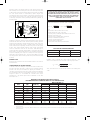
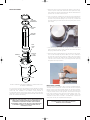
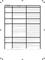
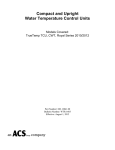
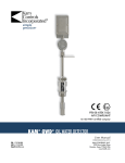
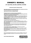
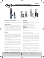
F-41-B
8/1/07
1:40 PM
Page 1
Bulletin F-41-B
Series SSM & SSB All Metal Flowmeters
Specifications - Installation and Operating Instructions
15.640
[397]
10.780
[273]
4.026
[102]
Series SSM 316 & SSB All Metal Flowmeters are ideal for dirty or
opaque fluids, high temperature and high pressure service and harsh
environments. The direct reading scale provides ±2% accuracy.
Flowmeters can quickly be disassembled without removing the body from
the pipeline for easy cleaning.
SAFETY PRECAUTIONS
Personnel safety should be considered before pressurizing and operating
the system. There are numerous possibilities for error in system operation
and maintenance as well as component installation. Because human eyes
must necessarily come into close proximity with the flowmeter to read it,
Dwyer Instruments, Inc. recommends that safety shielding such as a sheet
of transparent, high impact material be used in front of the meter. If
hazardous, toxic, or flammable fluids are being metered, recommended
safeguard should include methods to protect personnel from splash or
rebound. A method of quick, safe removal of dangerous fluids should also
be included.
INSTALLATION
PREPARATION: Series SSM & SSB All Metal Flowmeters are ready to
install as-is, although the sight tube may need repositioning so the scale is
visible after installation. First, remove the protective caps from the
connection ports. ALSO, REMOVE THE PLASTIC TUBING ABOVE THE
INLET CAP IN THE METER CORE TUBE! This tubing blocks the float
assembly in place during shipment. Check that the float moves freely within
the core tube, and that no packing materials are in the meter.
RECOMMENDED PIPING
Series SSM & SSB All Metal Flowmeters generally have no special straight
run or other piping requirements. Inlet piping should be the same size as
the meter connection. Some effect on meter accuracy may occur at high
flow velocities if inlet piping guidelines are violated. Please refer to the table
on the next page. When installing on different size pipe, use standard pipe
adapters and come into the meter inlet with a nipple 8 diameters long of
the same size for greatest accuracy. Control valves should be mounted on
the outlet side of the meter. The use of a three valve manifold around the
meter is suggested, as it allows uninterrupted process flow while the meter
is being cleaned.
PLUMBING-IN
While the flowmeters should be vertical, exact plumbness is not necessary.
A general rule is that if the meter appears plumb, it is close enough (even
if off by 10º, the predictable reading error is usually less than 1%). Pipe
should be cut to proper lengths to avoid stress on the meter. Avoid overtightening, and do no use wrenches on the body or sight tube. If using
DWYER INSTRUMENTS, INC.
P.O. BOX 373 • MICHIGAN CITY, INDIANA 46361, U.S.A.
2.680
[68]
MODEL SSM110,111,112
4.503
[114]
3/4" NPT
Ø 1.350 [34.3]
Ø 2.754
[70]
1-1/2" NPT
124072
2.810
[71.4]
5.695
[145]
Ø 4.010
3.710
[101.8]
[94]
MODEL SSM113,115
Ø 2.480
[63]
SPECIFICATIONS
Service: Compatible liquids.
Wetted Material: T316 SS, Alnico magnet, FKM O-ring.
Temperature Limits: 300ºF (149ºC), temperatures from 300˚F to 600°F
(149˚C to 316°C) require “hot top” sold separately.
Pressure Limits: 3/4” models: 1000 psig (68.9 bar) @ 250ºF (121ºC),
1-1/2”models: 800 psig (55 bar) @250ºF (121ºC).
(See the chart on pg. 6 for temperature vs.. pressure ratings.)
Accuracy: ±2% full scale.
Repeatability: ±0.5% of indicated flow rate.
Process Connections: 3/4” or 1-1/2” female NPT.
Scale Length: 3/4” models: 3.2” (8 cm); 1-1/2” models: 5.2” (13 cm).
Weight: 3/4” models: 5 lb (2.3 kg); 1-1/2” models: 13 lb (5.9 kg).
solvents in the vicinity of polysulfone sight tubes, the tube should be
removed until fumes clear.
SURGE & WATER HAMMER PREVENTION
Operating Limits are for non-shock conditions only. Flowmeters are more
accurate and less likely to be damaged when the fluid flow is smooth.
Water hammer is a hazardous phenomenon and should be eliminated from
any fluid system. Water hammer is a series of pressure shocks create by a
sudden change in the flow velocity of liquid in a pipe. This sudden change,
often caused by a fast acting valve or starting, stopping, or change in
speed of a pump, generates an immediate rise in pressure that sometimes
makes a noise similar to striking the pipe with a hammer. The pressure
wave is transmitted from the source throughout the system, subjecting
every component to the sudden shock. Pressure returns to normal only
when a larger vessel or pipe section is reached, the energy dissipated thru
friction and pipe expansion, or some component ruptures. Rupture of
piping, valves, flowmeters, or other components have obvious safety
ramifications that must be addressed.
Surge Chambers & Accumulators: Flowmeters are more accurate and less
likely to be damaged when the fluid flow is smooth. If the meter must be
installed on a line where reciprocating pumps causing pulsation are used,
surge chambers, accumulators, or desurgers are strongly suggested to
dampen the shock wave. This is a good, general practice for all
flowmeters.
SIGHT TUBE ROTATION: Series SSM & SSB All Metal Flowmeters use
magnetically-linked ball indicators and the scale usually may be positioned
over approximately a 300˚ range. However, the magnet position must also
be changed accordingly, requiring removal of the sight tube (see
“Disassembly”). On standard SSM & SSB All Metal Flowmeters as
Phone: 219/879-8000
Fax: 219/872-9057
www.dwyer-inst.com
e-mail: [email protected]
F-41-B
8/1/07
1:40 PM
Page 2
depicted in Figure 1, the magnet slides out of the carrier at the top of the
float assembly. The screw holding the carrier to the float may be loosened
to allow rotation of the carrier toward the desired scale location. Re-tighten
the screw (thread sealant is recommended), replace magnet, and
reassemble the meter (see “Assembly”). Verify that the ball indicator has
been “captured” by the magnet. If not, rotate the sight tube (DO NOT twist
on the edges of the plastic raceway assembly) until the ball is “grabbed” by
the float magnet.
CAUTION: DO NOT OPERATE THE FLOWMETER ON A SYSTEM
EXCEEDING THE OPERATING LIMITS OF THE UNIT. WHEN
CHANGING OPERATING CONDITIONS, MAKE SURE THAT THE
NEW SYSTEM CONDITIONS ARE WITHIN THE FLOWMETER
OPERATING LIMITS, AND ALL WETTED MATERIALS ARE
COMPATIBLE WITH THE FLUID.
CORRECTING READINGS FOR NEW LIQUID CONDITIONS
SEC A-A, TOP VIEW
A
A
MAGNET
METAL
PRESSURE
TUBE
Qa = Qs
BALL
INDICATOR
SNORKELGUIDE
POLYCARBONATE
PHENOLIC
COVER
RACEWAY
FIGURE 1
STARTUP: System flow should be started with the bypass valve open and
meter inlet and outlet valves closed. After the system is operating, open the
meter inlet valve gradually to equalize internal pressure. Then slowly crack
meter outlet valve and wait for float to stabilize. Finally, slowly open the
meter outlet and/or flow regulating valve all the way and close the system
by-pass valve. AVOID SUDDEN SURGES THAT CAUSE THE METER
FLOAT TO SLAM INTO THE TOP OF THE SIGHT TUBE! Although not
essential, the meter sight tube should be filled to a level above the float on
liquid systems. The snorkel tube (present in most standard models) allows
escape of entrapped gases except for a small pocket in the upper end
which helps cushion hydraulic shock. To assure proper filling and to flush
any foreign particles from the meter, operate the system at full flow briefly
at startup.
READING FLOW
Read flow directly from the scale as the number nearest to the center of
the ball indicator.
COMPENSATING FOR SYSTEM CHANGES
To find the correct flow reading for a system whose fluid conditions vary
from those for which the meter is scaled, use the conversion equations
provided. The most practical method of applying the formulae is to
calculate a conversion factor for the new system condition and multiplying
the scale reading by that factor. In the problems to the right, “Q’s” has been
assigned a value of “1” to determine the conversion factor. (Dwyer
Instruments, Inc. can provide special scales at additional cost for other
fluids and/or units.)
Ps(Pf-Pa)
√ Pa(Pf-Ps)
ds(df-da)
or Qa = Qs
√ da(df-ds)
Where:
Qa=Actual flow, GPM (or same units as scale)
Qs=Meter reading from scale, (scale units)
ps=Specific gravity of calibration liquid related to water in std.
atmosphere at 70˚F being 1.00
pa=Specific gravity of metered liquid, same base
ds=Density of calibration liquid, lbs/ft3
da=Density of metered liquid, lbs/ft3
pf=Specific gravity of meter float
df=Density of the meter float as per Table below
FLOAT SPECIFIC GRAVITIES/DENSITIES
Material
Stainless Steel
Brass
pf
df
8.05
8.30
501.1
516.6
EXAMPLE: Using a standard brass meter scaled for water (ps = 1.00),
what is the conversion factor for an oil with a specific gravity of 0.85?
Qa = 1.00 x
1.00 (8.30-0.85)
=1.096
√ 0.85 (8.30-1.00)
Thus, actual flow of the oil would be the observed scale reading times
1.096.
MAXIMUM FLOWS (WITHOUT EFFECTING ACCURACY)
FOR UNDERSIZED PIPES CONNECTED DIRECTLY TO FLOWMETER INLETS
PIPE
NPS
1/4
3/8
1/2
3/4
1
1-1/4
1-1/2
2
2-1/2
3
DATA
(ID)2
0.132
0.243
0.387
0.679
1.100
1.904
2.592
4.272
6.096
9.413
MAX. *
GPM LIQ.
1.72
2.98
4.74
8.31
13.47
23.32
31.74
52.29
74.56
115.2
ATMOS.
0.864
1.59
2.53
4.44
7.20
12.5
17.0
28.0
39.9
61.6
MAX. SCFM AIR @ †
100 PSIG
50 PSIG
6.74
3.80
12.4
7.00
19.8
11.1
34.7
19.5
56.1
31.7
97.2
58.8
132
74.6
218
123
311
176
480
271
200 PSIG
12.6
23.2
37.2
64.9
105
182
248
408
582
804
* Data per Cameron Hydraulic Data. Based on 5 FPS max. liquid velocity having no effect on flowmeters accuracy if the inlet pipe is smaller than the
meter connections.
† SCFM=0.445 x (psig + 14.7) x (ID)2. Based on 20 FPS max. air velocity having no effect on flowmeters accuracy if the inlet pipe is smaller than the
meter connections.
F-41-B
8/1/07
1:40 PM
Page 3
MAINTENANCE
Upon final installation of the Series SSM & SSB All Metal Flowmeters, no
routine maintenance is required. A periodic check of the system calibration
is recommended. The Series SSM & SSB All Metal Flowmeters are not field
serviceable and should be returned if repair is needed (field repair should
not be attempted and may void warranty). Be sure to include a brief
description of the problem plus any relevant application notes. Contact
customer service to receive a return goods authorization number before
shipping.
CORRECTING READINGS FOR NEW GAS CONDITIONS
Qg = Qs
Pg x Ts x Ps
√ P xT xP
s
g
g
Where:
Qg=SCFM, corrected to new conditions
Qs=SCFM read on meter scale
Pg=Operating pressure, psia (psig + 14.7)
Qs=Pressure stated on scale, psia (psig + 14.7)
Tg=Operating temperature, absolute (˚F +460)
Ts=Temperature stated on scale, absolute (˚F + 460)
Pg=Specific gravity of metered gas
Ps=Specific gravity stated on scale
EXAMPLE: If using a standard meter scaled for SCFM Dry Air @ 100 psig,
70˚F on argon (SP. GR.=1.378) at 50 psig, 100˚., what would the
conversion factor be?
Qa = 1.00
64.7 x1.00 x530 = 0.622
√ 114.7 x1.378 x560
Thus, actual flow of the argon would be the observed scale reading times
0.622.
STEAM
Series SSM & SSB gas flowmeters may be used for vapors such as steam.
The conversion factor may be determined with the following formula:
5.879
Mfh = Qm _______
√Sv
Where:
Mfh=Actual flow, lbs/hr.
Qm=Meter scale reading, Std. (SCFM Dry Air @ 100 psig, 70˚F)
Sv=Specific volume of media (from steam table)
EXAMPLE: When using a standard gas meter scaled from SCFM Dry Air @
100 psig, 70˚F, what is the conversion factor for lbs/hr. steam at 50 psig,
300˚F?
5.879
Mfh =
√6.727
Thus, actual flow of steam in lbs/hr. would be the observed scale reading
times 2.267.
VISCOSITY CONSIDERATIONS
Each liquid flowmeter has so-called “Viscosity Immunity Ceiling” (V.I.C.).
Usually, if the viscosity of the metered liquid is less than the V.I.C., the
meter will be influenced significantly, and must be calibrated for that
viscosity. Effects of viscosity on a given flowmeter are not always
predictable. Two apparently similar liquids with comparable densities and
viscosities may impact meter calibrations quite differently. The table below
provides general guidelines for the typical maximum viscosity for meter
models without affecting accuracy.
AVERAGE V.I.C., CENTISTOKES, FOR STANDARD
“THRU VIEW” FLOWMETERS
100% GPM,
3/4” METERS
CTS
100% GPM,
1-1/2” METERS
CTS
0.54-0.80
1.20-2.60
3.80-7.00
10.0-23.0
0.54-0.80
1.20-2.60
3.80-7.00
10.0-23.0
0.54-0.80
1.20-2.60
3.80-7.00
10.0-23.0
0.54-0.80
1.20-2.60
3.80-7.00
10.0-23.0
F-41-B
8/1/07
1:40 PM
Page 4
METER DISASSEMBLY
1. Remove the raceway cover by removing the stainless screw at the top,
and lift it up and off the meter. Remove the black phenolic raceway,
being careful not to displace the ball indicator. Remove the ball indicator
by hand, and set it where it will not be lost.
NEW SPIRAL
RETAINING RING
2. Using a screwdriver, carefully pry the notched end of the spiral retaining
ring out of the body groove. Move the screwdriver blade under the ringthe action is very much like putting a key on a key ring. Continue until
the entire spiral ring has been removed from the groove (please see the
photo below).
INNER FLANGE
RING
SIGHT TUBE
ASSEMBLY
STATIC
O RING
SEAL
MAGNET(S)
CORE TUBE/
FLOAT
ASSEMBLY
3. Using hands only, pull the sight tube straight up out of the body with a
slight twisting motion, lifting it clear of the body and snorkel. The inner
flange ring will lift off with the sight tube.
4. Remove the float assembly by lifting it up and away from the snorkel.
The core tube assembly may then be lifted out. If stuck, CAREFULLY
pry at the top of the slot with a brass rod, taking care not to damage
the body or core tube. The spider ring and O-ring will come out with the
core tube. If the core tube is stuck, try removing the metal spider ring
first (please see the photo below).
BODY
FIGURE 2: PARTIALLY EXPLODED DRAWING OF SERIES SSM & SSB
ALL METAL FLOWMETERS
It is not necessary to remove the flowmeters from the pipeline for cleaning
or replacing parts. The body remains plumbed into the pipe, allowing easy
service and even installation of the different sensing elements to
accommodate new flow rates or fluids. Figure 2 shows some of the major
components. Step by step disassembly and reassembly instructions and
photos are included in the following.
INSPECTION & CLEANING
Inspect parts for nicks, scratches, chips, wear, and contaminant build-up.
The edges of the core tube slot, ID of the core tube and OD of the piston
(largest section at the float assembly bottom) are precision machined.
Damage to these areas can destroy the meter’s accuracy. Also inspect the
O-ring, the bottom section of the sight tube, and the inside of the upper
body section. Damage to these areas may result in leaking. Clean, rinse,
and dry all parts carefully, including the O-ring, preferably with a mild
detergent and water and a soft cloth or soft tube brush. If solvents are
used, make sure they are compatible with meter parts.
CAUTION: BE SURE PRESSURE IS FULLY VENTED AND FLUIDS
COMPLETELY DRAINED BEFORE DISASSEMBLING THE
FLOWMETER. DISCONNECT POWER TO ELECTRONIC
ACCESSORIES. WEAR SAFTEY GLASSES AND PROTECTIVE
CLOTHING IF THERE IS A CHANCE OF EXPOSURE TO
HAZARDOUS FLUIDS!
CAUTION: DO NOT SCRAPE OR USE ABRASIVE
MATERIALS FOR CLEANING!!!
F-41-B
8/1/07
1:40 PM
Page 5
FLOWMETER ASSEMBLY
In general, replace all parts in reverse order of the disassembly.
1. Place the slotted meter tube into the body, aligning the “key” at the
bottom of the tube with the keyslot in the bottom of the body.
6. Slide the inner flange ring over the sight tube. When properly seated, the
top of the flange ring should be flush with the bottom edge of the snap
ring groove.
2. Place the spider over the meter tube with the “notched leg over the
snorkel tube or guide rod. Slide the spider down to the meter tube’s
shoulder.
3. Place the meter float in the meter tube, aligning the notch in the
indicator disk with the snorkel.
4. Seat the O-ring on the sight tube, lubricating it with a small amount of
service-compatible silicone grease or petroleum jelly to facilitate
replacement.
5. Using hands only, press the sight tube firmly down into the meter body
with a twisting motion. Be careful not to rock the sight tube side to side
and bend the snorkel tube/guide inward where it might interfere with
float movement. Rotate sight tube as necessary for scale visibility
and/or alignment of the raceway screw.
7. Separate the coils of the spiral retaining ring, and insert one end into the
body groove. Wind the ring into the groove, making sure the ring is
properly seated. Then replace the ball indicator (the tip of a screwdriver
can be used to help locate the magnet), and replace the raceway and
raceway cover.
If reassembled correctly, the center of the ball indicator should lineup with
the scale “zero” (either dotted black or scribed line). If it does not,
disassemble the meter completely and carefully reassemble it, making sure
the slotted meter tube is completely seated in the body.
If new flow internals are used, the scale may have to be remounted on the
sight tube. Depending on the model type, this can be done either by
loosening the mounting screw, or reattaching the scale with double sided
adhesive (new flow internals are shipped with a new scale).
F-41-B
8/1/07
1:40 PM
Page 6
REPLACEMENT PARTS
Under proper care, there should be no need to stock replacement parts. If
the service or environment is quite harsh, or frequent meter disassembly
dictated, a spare O-ring may be desirable.
Otherwise, parts only need to be replaced if damaged. Any visible damage
to the entire surface of the O-ring or sight tube (particularly from the bottom
edge) indicates need for replacement. To insure accuracy, the inside
surface of the meter core tube, slot edges, and OD of the float piston
should be free of nicks, chips, with no visible erosion of any surfaces. If
abrasive particles are suspended in the meter fluid, it may be desirable to
keep replacement core tube/float assemblies on hand (Dwyer Instruments,
Inc. may also be able to recommend a more abrasive-resistant
construction).
To order parts, include the model and serial number of the units involved,
and description of the part ordered. If converting the meter to a new
application, in addition to the model and serial numbers, SEND DWYER
INSTRUMENTS, INC. COMPLETE APPLICATION DATA INCLUDING
FLUID, MAXIMUM FLOW RATE, MAXIMUM AND OPERATING
PRESSURES AND TEMPERATURES, AND APPLICATION PARTICULARS
OR FLUID CHARACTERISTICS. This information is essential for Dwyer
Instruments, Inc. to provide proper items, and verify that the new
application is within the operating limits of the flowmeter.
TEMPERATURE VS. PRESSURE, OPERATING LIMITS, “SERIES SSM & SSB” ALL METAL FLOWMETERS*
METER SIZE
& MATERIAL
MAXIMUM NON-SHOCK WORKING PRESSURE, PSIG @ ˚F
400˚F †
300˚F †
350˚F †
450˚F †
500˚F †
600˚F †
0˚F
70˚F
6 (3/4” NPT)-Stainless
1000
1000
1000
990
970
950
930
900
12 (1-1/2” NPT)-Stainless
800
800
800
790
780
770
760
750
* OPERATING LIMITS GIVEN ARE BASED ON WATER OR AIR. FOR MORE SEVERE SERVICE, CORROSIVE, AND OTHER MEDIA AND/OR ENVIRONMENTAL FACTORS, AN
ADDITIONAL CORRECTION FACTOR DOWN-RATING THESE LIMITS MAY BE REQUIRED. LIMITS ARE BASED ON TESTING AND PRACTICAL EXPERIENCE. POSSIBLE
EXTREME APPLICATIONS CONDITIONS CANNOT BE FORESEEN. THUS, DATA OFFERED ONLY AS A GUIDE. IT IN NO WAY CONSTITUTES A SPECIFIC
RECOMMENDATION OR WARRANTY EXPRESSED OR IMPLIED.
† OPERATING TEMPERATURES ABOVE 300˚F REQUIRE SPECIAL HIGH TEMPERATURE MODIFICATIONS.
F-41-B
8/1/07
1:40 PM
Page 7
TROUBLESHOOTING
USUAL CAUSE
SUGGESTED REMEDY
FLOAT HANG-UP:
Caused by particles, sludge, etc. (including failure to
remove the plastic tubing used to block meter float during
shipment) inside the core tube and/or sight tube holding
float. A bent snorkel tube/guide rod (usually caused by
careless disassembly or violent surges) may also be
causing float to stick. Violent surges may also unseat the
internals in extreme cases.
Remedies include tapping the meter gently to temporarily
dislodge the float, but if problem reoccurs, meter should
be disassembled & cleaned, and/or snorkel/guide rod
straightened. If hang-up caused by sludge or pipe scale,
clean lines & install a filter or other form of cleaner in supply
line. If surges have caused the internals to unseat, install a
desurger, accumulator, etc.
FLOAT BOUNCE:
Caused by pumping/compressor surges or other pulsation
sources, loose valve disks or similar mechanical
components, extreme violation of inlet piping
recommendations, or for gas applications, harmonics
commonly found in systems with low pressure, low density
gas.
Modification of piping, such as addition of a desurger,
receiver, accumulator, vibration eliminators, loops, hoses,
etc. between the source and meter should remedy the
problem. Severe vibration may ultimately damage the
meter, and should be avoided. If “bounce” seems to be
from some other source, or shocks such as “water
hammer” (a potentially dangerous condition), discontinue
using the meter and contact Dwyer Instruments, Inc.
LOSS OF BALL INDICATOR:
Caused either by rotating the sight tube without realigning
the float magnet, or sudden flow surges or shocks.
Check the ball alignment to magnet by removing the
raceway cover and using the tip of a small screwdriver to
locate the float magnet. Rotate the sight tube as required,
and replace raceway (or disassemble meter to change
magnet position if required). If the alignment is okay,
eliminate system shock or surges with desurgers or
accummulators.
APPARENT FALSE
READINGS, LIQUID
METERS:
Liquid density not according to calibration data (differ
temperature or new liquid or liquid mixture), excessive
dissolved or suspended solids or gases, partial clogging of
core tube slot or foreign matter interfering with float
movement, or viscosity levels above the meter’s immunity
index (V.I.C.)
By determining the actual density (due to changes in
mixture, temperature, etc.), the correction formulae may be
applied. If dissolved gases are in the liquid, some
elimination means should be provided on the supply side
(also recheck all piping, as improper seals at connection
points are common sources of air in the liquid). If the
metered liquid is near the boiling point producing partial
“flash gas” at the meter, relocate the meter to point of
lower temperature and/or higher pressure, or cool lines
and/or increase system pressure. Note: It is potentially
dangerous to meter near the “flash point” of any fluid, and
this practice should be avoided. Consult Dwyer
Instruments, Inc. for recommendations. The previous
recommendations regarding cleaning the meter and/or
filtration will also solve problems due to dirt. If metering
liquids with high viscosities, consult Dwyer Instruments,
Inc. (may require special calibration). If none of these
causes seem to be present, contact Dwyer Instruments,
Inc. for assistance.
SYMPTOM
NOTE: If the meter is suspected of giving false readings,
and none of the causes mentioned is found, please advise
Dwyer Instruments, Inc. as to the method used in
determining the suspected flow “error”. Each Flowmeter is
individually calibrated by traceable methods, and carefully
inspected. There may be some error in checking the meter
against another standard.
APPARENT METER
READING MIGRATION
(reading changes but flow
appears constant):
Frequently caused by use of soft disc type valves, which
may need to be replaced with a valve more suited to flow
control. Can also be indicative of changing fluid conditions
(density, viscosity, etc.). Problems with other elements of
the flow system, including leaks, clogged filters,
pump/compressor wear, etc. may first appear as a change
in meter reading-one of the functions of a flowmeter.
Verifying the proper fluid conditions are known and
applying correction formulae as needed will remedy
problems associated with changing fluids. Cleaning,
servicing, and replacement and/or repair of other system
components may be required.
LEAKAGE:
If at the junction of the body and sight tube, it is indicative
of either (a) damaged O-ring (most common); (b) damaged
sight tube; or (c) damage to the gland section of the body.
It may also be caused by improper reassembly of the
flowmeter in the field.
If there is leakage at the pipe connections to the meter, it
is probably caused from over-tightening pipes on a prior
installation (or the initial installation).
Replace any damaged parts immediately, using the proper
assembly procedures indicated in this instruction and the
assembly detail drawings.
Remove the body and inspect for damage-if none is
visible, check pipe threads, reapply proper thread
lubricant/sealant, and reinstall. If leak persists, replace
meter body.
NOTE: Flowmeters are hydrostatically pressure tested before they are shipped. Dwyer Instruments, Inc. encourages you to contact your Dwyer Instruments, Inc. representative or
the factory with any questions regarding proper installation and operation of our flowmeters.
F-41-B
8/1/07
1:40 PM
Page 8
©Copyright 2007 Dwyer Instruments, Inc.
Printed in U.S.A. 8/07
DWYER INSTRUMENTS, INC.
P.O. BOX 373 • MICHIGAN CITY, INDIANA 46361, U.S.A.
Phone: 219/879-8000
Fax: 219/872-9057
R1-443566-00
www.dwyer-inst.com
e-mail: [email protected]