1
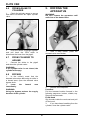
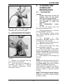
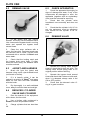
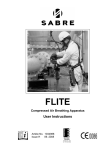
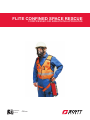
FLITE CONFINED SPACE RESCUE
COMPRESSED AIR BREATHING APPARATUS
1034990 D
05.2012
CE 0086
Contents
WARNINGS ....................................................................................................................................... ii
1.
INTRODUCTION ...................................................................................................................... 1
1.1
BREATHABLE AIR .......................................................................................................... 1
1.2
AIRLINE PRESSURE AND FLOW .................................................................................. 1
1.3
TRAINING ....................................................................................................................... 1
1.4
SERVICING .................................................................................................................... 2
1.5
PARTS AND ACCESSORIES ......................................................................................... 2
2.
TECHNICAL DESCRIPTION.................................................................................................... 2
2.1
GENERAL ....................................................................................................................... 2
2.2
DEMAND VALVE ............................................................................................................ 2
2.3
HEADPIECES ................................................................................................................. 3
2.4
REDUCER / CYLINDER VALVE ..................................................................................... 3
2.5
CYLINDERS .................................................................................................................... 3
2.6
SAFETY HARNESS ........................................................................................................ 4
2.7
QUALITY ATTRIBUTES .................................................................................................. 4
3.
PRE-USE CHECKS .................................................................................................................. 4
3.1
HEADPIECES ................................................................................................................. 4
3.2
JACKET AND HARNESS ................................................................................................ 5
4.
DONNING AND OPERATING PROCEDURES........................................................................ 5
4.1
JACKET AND SAFETY HARNESS ................................................................................. 5
4.2
HEADPIECES ................................................................................................................. 6
4.2.1
Panaseal Facemask .............................................................................................. 6
4.2.2
ELSA Hood ............................................................................................................ 6
4.3
POSITIVE PRESSURE TEST ......................................................................................... 7
4.4
LEAK TEST ..................................................................................................................... 7
4.5
CYLINDER SUPPLY TEST ............................................................................................. 7
4.6
FROM AIRLINE TO CYLINDER ...................................................................................... 8
4.7
FROM CYLINDER TO AIRLINE ...................................................................................... 8
4.8
BYPASS .......................................................................................................................... 8
5.
DOFFING THE APPARATUS .................................................................................................. 8
6.
CLEANING AND SCHEDULED MAINTENANCE.................................................................... 9
6.1
FACEPIECES ................................................................................................................. 9
6.2
DEMAND VALVE .......................................................................................................... 10
6.3
JACKET AND HARNESS .............................................................................................. 10
6.4
REDUCER / CYLINDER VALVE AND CYLINDER ........................................................ 10
6.5
CHECK APPARATUS ................................................................................................... 10
6.6
DEMAND VALVE .......................................................................................................... 10
6.7
RECORD DETAILS OF CHECKS ................................................................................. 11
6.8
STORAGE..................................................................................................................... 11
6.9
MONTHLY MAINTENANCE .......................................................................................... 11
6.10
ANNUAL MAINTENANCE ............................................................................................. 11
Registered office: Scott Safety, Pimbo Road, West Pimbo,
Skelmersdale, Lancashire, WN8 9RA, United Kingdom.
i
WARNINGS
Please Read Carefully and Fully Understand
This manual is for use by personnel trained in the use and care of compressed air
breathing apparatus (BA) and MUST NOT be used as a self-teaching guide by untrained
users. Failure to understand or adhere to these instructions may result in injury or death.
Scott Safety have taken great care to ensure that the information contained within this
manual is accurate, complete and clear. However, Training and Technical Support
Services will be pleased to clarify any points in the manual and answer any questions on
Scott Safety breathing apparatus.
The following warnings are in accordance with certifying authority requirements and
apply to the use of breathing apparatus in general:
Breathing apparatus users must be fully trained in the use and care of airline
and self-contained, compressed air breathing apparatus.
Ensure that the selection of the apparatus type is sufficient for the tasks
being undertaken and the hazards likely to be encountered. Please refer to
National Regulations for guidance.
In order to ensure optimum performance and user safety, the apparatus
must be tested and serviced in accordance with Section 6 - Cleaning and
Scheduled Maintenance and the notes in Section 1 - Training and Servicing.
The quality of air used to supply and charge breathing apparatus must meet
the requirements of EN 12021, Annex A. See Section 1 for details.
The wearing of beards, side-burns or spectacles may adversely affect the
sealing of a facemask to the wearer’s face.
The apparatus is not approved for fire fighting or for use close to high heat
sources.
The apparatus must not be used underwater.
DISCLAIMER
Failure to comply with these instructions or misuse of the apparatus may result in death, injury
or material damage and invalidate any resulting warranty or insurance claims.
COPYRIGHT
This manual must not be copied in part or in whole, or used for purposes other than it’s
intended purpose without the written permission of Scott Safety.
ii
FLITE CSR
1.2
1. INTRODUCTION
1.1
BREATHABLE AIR
Number of
Wearers
Air for compressed air breathing
apparatus may be natural or synthetic. A
typical composition of natural air is shown
in Table 1.
ELEMENT
MASS %
(Dry Air)
23.14
20.948
NITROGEN
Supply Pressure bar
(psi)
Airflow
(L/min)
1
5.5 – 9.5 (70 – 130)
300
2 (1 pair)
5.5 – 9.5 (70 – 130)
450
Table 2: Supply pressure and airflow
VOLUME%
(Dry Air)
OXYGEN
AIRLINE PRESSURE
AND FLOW
External air supplies must conform to the
supply pressures and flow rates listed in
Table 2 when measured at the wearer
end of the airline.
75.52
78.08
ARGON
1.29
0.93
CARBON
DIOXIDE
0.05
0.031 4
HYDROGEN
0.000 003
0.000 05
NEON
0.001 270
0.001 818
1.3
Personnel who use self-contained,
compressed air breathing apparatus must
be fully trained in accordance with these
instructions and national regulations.
HELIUM
0.000 037
0.000 524
KRYPTON
0.000 330
0.000 114
XENON
0.000 039
0.000 009
An airline flow tester is available from
Scott Safety under Article Number
1035978.
Table 1: Breathable Air
TRAINING
These instructions cannot replace an
accredited training course run by fully
qualified instructors in the proper and
safe use of Scott Safety breathing
apparatus.
There is an increased fire risk when the
oxygen content is above the value shown
in Table 1.
The purity/quality of air used to supply
and charge breathing apparatus must
conform
to
European
Standard
EN 12021.
Please contact Training and Technical
Support Services or your Scott Safety
distributor for training course details.
Training and Technical Support
Services:
Contaminants must be kept to a minimum
and must not exceed permissible
exposure levels.
Scott Safety
Pimbo Road, West Pimbo,
Skelmersdale, Lancashire,
WN8 9RA, United Kingdom.
Air filters must be suitable for the quality
of air used and the air must be tested
periodically to ensure that the supply
reaches these standards. The air must be
free from the odour of oil. The odour
3
threshold is 0.3mg/m .
Tel: +44 (0) 1695 711711
Fax: +44 (0) 1695 711775
Air for use with compressed air airlines
should have a dew point sufficiently low
to prevent internal freezing.
National Regulations for compressed
airline breathing apparatus must be
observed.
1
FLITE CSR
1.4
SERVICING
2. TECHNICAL
DESCRIPTION
FLITE Confined Space Rescue (CSR)
must be serviced at scheduled intervals
by personnel who have completed a
formal training course and hold a current
certificate for servicing and repairing
Scott Safety breathing apparatus. Details
of the Servicing Schedule are contained
within the Scott Safety FLITE Service
Manual, copies of which may only be
obtained by registered holders of a
current certificate.
2.1
Non-return valves in the airline connector
and cylinder connector permit the
apparatus to be used without a cylinder
OR without the airline.
Your Scott Safety distributor or Training
and Technical Support Services at
Scott Safety will be pleased to provide
training course details and quotes for
service contract. Please see above for
contact details.
1.5
GENERAL
FLITE CSR is a self-contained, open
circuit, compressed air, positive pressure
breathing apparatus with a safety
harness. An airline version permits the
wearer to disconnect the airline while in a
hazard area and breathe from the
compressed air cylinder.
A carbon fibre/aluminium cylinder should
be used with apparatus that is to be used
for full shift periods. A steel cylinder
should NOT be used for full shift working.
PARTS AND
ACCESSORIES
The breathing apparatus comprises a full
facemask or hood, a demand valve and a
pigtail with CEN connector for attaching
to the supply airline. There are two
cylinder options that can be provided with
the apparatus.
Customer Services provide an efficient,
friendly customer contact point for
ordering new apparatus, spare parts and
accessories.
Customer Services:
Providing the apparatus is serviced
regularly in accordance with the service
requirements detailed in the FLITE
Service Manual, there are no shelf life
limits.
Scott Safety
Pimbo Road, West Pimbo,
Skelmersdale, Lancashire,
WN8 9RA, United Kingdom.
Tel: +44 (0) 1695 711711
Fax: +44 (0) 1695 711775
2.2
DEMAND VALVE
Airflow into the headpiece is controlled by
the demand valve, which is attached to
the headpiece by a quick-fit connection.
2
FLITE CSR
The demand valve can be closed by the
wearer pressing a reset button to enable
the headpiece to be removed without loss
of compressed air to the atmosphere.
2.4
The reducer/cylinder valve is a spring and
piston device with a handwheel to
open/close the cylinder valve.
When the demand valve is next used, the
first breath taken by the wearer opens the
demand valve.
The pressure output to the headpiece
demand valve is between 5 and 11 bar.
Protection from over-pressurisation is
provided by a pressure relief valve that
operates at 11.5 bar.
The bypass knob enables an unregulated flow of compressed air into the
headpiece to protect the user in the event
of the demand valve failing in a ‘no flow’
condition.
2.3
REDUCER / CYLINDER
VALVE
A pressure gauge indicates the cylinder
pressure. The red sector on the gauge
indicates when the cylinder is almost
empty.
HEADPIECES
Headpieces are stored in a bag attached
to the jacket. The bag has a pictogram of
the donning procedure.
When the cylinder is opened, air flows
through the reducer to the demand valve.
WARNING:
As the donning procedure is specific
to the headpiece type, it is important
that after use, facemasks are replaced
in facemask bags and hoods in hood
bags.
2.5
CYLINDERS
The following cylinders are approved for
use with FLITE:
10 minute cylinder:
There are two types of positive pressure
headpieces available with FLITE CSR:
PanaSeal or ELSA Hood; both have:
•
An ori-nasal inner mask to minimise
carbon dioxide dead space and
prevent visor misting.
•
A speech diaphragm that reduces
wearer speech distortion.
•
A spring-loaded exhale valve that
limits the positive pressure within
the headpiece.
•
Breathing
apparatus
bayonet
demand valve fitting.
Free air capacity:
400 litres
Charging pressure:
200 bar
Material:
Alloy Steel
Specification:
CE
PanaSeal is a positive pressure, full
facemask that is held in place by a fivepoint adjustable head harness and a left,
quick-fit
demand
valve.
The
polycarbonate visor conforms to BS2092
Grade 1 for impact and optical clarity.
Duration at 40 L/min:
10 minutes
Weight (charged):
5.5 Kg
13 minute cylinder:
Free air capacity:
540 litres
Charging pressure:
300 bar
Material:
Carbon Fibre / Aluminium
Specification:
CE
Duration at 40 L/min:
13 minutes
Weight (charged):
4.3 Kg
When the supply airline is disconnected,
a non-return valve in the supply airline
protects the airline from contamination
whilst a second non-return valve in the
FLITE pigtail hose prevents air loss from
the cylinder supply.
ELSA Hood is a full hood that fits most
head sizes. It has an elasticated neck
seal and a front-fitting demand valve.
When FLITE is used with an airline
supply and the cylinder is disconnected, a
non-return valve in the cylinder hose
prevents loss of air.
3
FLITE CSR
2.6
SAFETY HARNESS
3. PRE-USE CHECKS
The safety harness is sewn into a highvisibility jacket and is approved for use
with personnel weighing up to 100 Kg.
3.1
HEADPIECES
1.
Remove headpiece from its bag.
Peel the Visorguard protective film from
the facemask and store carefully for use
later.
The safety line attachment point, located
between the wearer’s shoulders, is
capable of accepting connectors of up to
25mm diameter.
2.
Check that the mask/hood is clean
and the visor is clear and undamaged.
Slacken the facemask head harness.
The harness is fully adjustable. A harness
tail with a D-ring provides an attachment
point for the pigtail and relieves the pull of
the airline hose. The harness also
supports the cylinder bag and headpiece
bag.
The high-visibility jacket reduces the
possibility of the apparatus snagging. It
has stowage points for a radio, Firefly
ASDU and a Minigas gas detector.
2.7
QUALITY ATTRIBUTES
FLITE CSR is approved to the following
European Standards:
•
EN 139 : 1993 (Respiratory
Protective Devices – Compressed
Airline Breathing Apparatus).
•
EN 402 : 1993 (Respiratory
Protective Devices for Escape).
3.
Pull the locking catch, turn the
demand valve clockwise and withdraw it
from the headpiece.
FLITE CSR is ‘CE’ marked in accordance
with EEC Directive EC/686/1986.
The safety harness is approved to
BS EN 361 : 1993 and is also ‘CE’
marked.
Scott Safety Breathing Apparatus is an
ISO9001 (BS5750 Pt 1) approved
Division of Scott Safety.
2.8
NOTIFIED BODIES
Inspec International Limited (No. 0194)
56 Leslie Hough Way,
Salford,
Greater Manchester,
M6 6AJ,
England.
4.
Check that the orange O-ring on
the demand valve is in good condition
and attach the demand valve to the
facemask.
BSI (0086)
Kitemark Court,
Davy Ave,
Knowlhill,
Milton Keynes,
MK5 8PP.
England.
5.
Twist the demand valve gently to
check that the locking catch is engaged.
4
FLITE CSR
6.
Check that the bypass knob is in
the OFF position and press the black
rubber reset button on the demand valve.
3.2
4. DONNING AND
OPERATING
PROCEDURES
JACKET AND HARNESS
1.
Fully
slacken
the
shoulder straps and leg strap.
4.1
waistbelt,
JACKET AND SAFETY
HARNESS
1.
Don the jacket and safety harness
so that the demand valve hose is on the
right shoulder and the cylinder is on the
left hip.
2.
Tighten the shoulder straps for a
secure, comfortable fit.
2.
Check that the pigtail shackle is
attached to the D-ring and that the
shackle nut is fully tightened.
3.
Check that the cylinder is full and
held securely in it’s bag.
3.
Fasten the waist-belt and leg strap.
4.
Remove the pigtail connector dust
cap. Check that the connector is clean
and in good condition. Check that there is
no damage or excess wear to the
harness.
5.
Replace any items that are
damaged or show signs of excessive
wear. DO NOT use equipment that fails
any of the above checks.
4.
Remove the pigtail coupling dust
cap. Check that the connector is clean
and in good condition.
6.
Check the airline supply hose for
wear or damage. Check the quality and
pressure of the external supply air.
5
FLITE CSR
5.
Press the demand valve reset
button and connect the pigtail to the
airline. Pull the airline to ensure that the
coupling is securely connected.
4.2
4.2.1
4.
Tighten the head harness straps in
the following sequence: bottom, middle,
top. DO NOT OVER-TIGHTEN.
5.
Take a sharp breath to actuate the
first breath mechanism.
HEADPIECES
4.2.2
Panaseal Facemask
1.
1.
Withdraw the facemask from its
bag. Remove the Visorguard and store in
the facemask bag.
ELSA Hood
Withdraw the hood from its bag.
2.
Insert hands, palms together, into
the hood and stretch the elasticated neck
seal. Pull the hood over the back of the
head and then over the face.
2.
Hang the facemask from the neckstrap and attach the demand valve. Twist
demand valve gently to ensure that it is
securely attached.
3.
Fit the chin into the chin-cup and
pull the head harness over the back of
the head, ensuring that no hair is trapped
under the face seal.
6
FLITE CSR
4.4
LEAK TEST
1.
Hold your
carefully for leaks.
breath
and
listen
2.
If a leak is detected, adjust the
facemask and head harness or hood
neck-seal. Repeat the test. If the leak is
still present, the apparatus must be
returned for repair.
4.5
CYLINDER SUPPLY
TEST
3.
Check that the inner mask fits
properly over the mouth and nose. Inhale
sharply to activate the first breath
mechanism.
4.3
POSITIVE PRESSURE
TEST
1.
Open the cylinder valve.
1.
Take a deep breath to activate the
first breath mechanism.
2.
Gently insert fingers into the
facemask seal or hood neck-seal and
check that there is a good flow of air from
the headpiece.
2.
Push the CEN coupling together,
pull back the airline connector collar and
release the airline.
3.
Remove fingers from the seal and
allow the mask/hood to re-seal.
3.
Check that there is a plentiful
supply of air into the face-piece.
4.
DO NOT use an apparatus that
fails this test.
5.
If no leaks are detected, the
apparatus is ready for use.
7
FLITE CSR
4.6
FROM AIRLINE TO
CYLINDER
5. DOFFING THE
APPARATUS
1.
Check the cylinder gauge to ensure
that there is sufficient air. Open cylinder
valve.
WARNING:
DO NOT remove the apparatus until
well clear of the hazard area.
2.
Push the airline couplings together
and pull back the CEN collar to
disconnect the hose from the pigtail.
4.7
1.
Take a deep breath, press the
demand valve reset button.
FROM CYLINDER TO
AIRLINE
1.
Connect the airline to the pigtail
and close the cylinder valve.
WARNING:
If the cylinder valve is not closed, the
cylinder will empty.
4.8
BYPASS
1.
In the unlikely event that the
demand valve stops delivering air while in
a hazard area, open the demand valve
bypass knob.
2.
Leave
immediately.
the
hazard
area
2.
Release the headpiece:
PanaSeal
Pull the harness buckles forward in the
following sequence: bottom, middle, top.
Remove the facemask.
ELSA Hood
Slip thumbs inside the neck-seal and pull
off the hood.
WARNING:
Using the bypass reduces the supply
duration of the cylinder.
3.
If you have been breathing from the
cylinder, close the cylinder valve.
8
FLITE CSR
6. CLEANING AND
SCHEDULED
MAINTENANCE
6.1
FACEPIECES
Cautions:
•
DO NOT allow water to enter the
demand valve. Fit the yellow
dust cap to the demand valve.
•
Use ONLY specified substances
and methods to clean the
apparatus.
•
DRY
THOROUGHLY
before
storage.
1.
Pull the red release catch and
disconnect the demand valve.
4.
Push the airline couplings together
and pull back the CEN collar to
disconnect the hose from the pigtail.
2.
Wash the headpiece in a hand-hot
solution of DistelTM and water.
5.
Open the demand valve bypass to
vent any compressed air from the system.
3.
Rinse thoroughly in clean running
water, paying particular attention to the
exhale valve.
4.
Dry
thoroughly
at
room
temperature. DO NOT expose to high
temperatures or direct sunlight.
5.
When dry, wipe the facemask seal
with a DistelTM disinfectant wipe.
6.
Check that the inhale valve flaps
are not damaged or distorted.
7.
When the headpiece is dry, polish
the visor with a soft, clean, lint-free cloth.
Replace the PanaSeal Visorguard (Article
Number 1031836). Slacken the facemask
head harness ready for use.
8.
Stow headpiece in the stowage bag
provided.
6.
Fit the dust cap on the CEN pigtail
coupling.
Notes:
DistelTM cleansing and disinfecting fluid is
available in 1 litre and 5 litre containers
from Scott Safety under Article Numbers
2008247 and 2008248 respectively.
7.
Release the waist-belt and leg
strap. Remove the apparatus.
8.
Clean and check the apparatus in
accordance with Section 6 – Cleaning
and Scheduled Maintenance before
returning it to service.
Pump dispensers suitable for use with the
above are also available under Article
Numbers 1017672 (1 litre) and 1017670
(5 litres).
DistelTM disinfecting wipes are available in
packs of 20 sachets (Article Number
2004225) or drums of 100 wipes (Article
Number 1017652).
9
FLITE CSR
6.2
DEMAND VALVE
6.5
CHECK APPARATUS
1.
Check the apparatus thoroughly for
signs of damage and wear. If any of the
components are damaged or worn, the
apparatus (together with an explanatory
note) must be returned for servicing.
2.
Check that the cylinder valve
handwheel turns smoothly and does not
stick.
3.
Check that the cylinder is full. If it is
not, the equipment must be withdrawn
from service for the cylinder to be recharged.
6.6
DEMAND VALVE
1.
Fit the yellow dust cap (Article
Number 1033545) over the demand valve
inlet. Immerse the bypass knob in running
water and operate the bypass knob
several times.
2.
Clean the outer surfaces with a
clean, lint-free cloth. Persistent marks can
be removed with a clean, lint-free cloth
moistened with a solution of DistelTM and
warm water.
3.
Check that the locking catch and
the bypass knob move freely. If either
does not move freely, the demand valve
must be serviced.
6.3
1.
Operate the locking catch several
times to check that it does not stick. The
locking catch should spring back to it’s
original position without sticking.
JACKET AND HARNESS
1.
Brush dirt from the jacket and
harness using a stiff nylon-bristled brush
(nail brush or similar).
2.
Operate the bypass knob several
times and check that it does not stick and,
when it is released, always rests in the
ON or OFF position.
2.
If it is heavily soiled, it can be
soaked in a solution of DistelTM and warm
water for one hour and then scrubbed
with the brush.
3.
Check that the demand valve Oring is in good condition.
3.
Dry thoroughly in a well-ventilated
room, away from direct heat and sunlight.
6.4
REDUCER / CYLINDER
VALVE AND CYLINDER
1.
Dust the exterior of the equipment
with a clean, lint-free cloth.
2.
Use a lint-free cloth moistened in
DistelTM to clean off persistent marks.
3.
full.
Charge cylinders that are less than
10
FLITE CSR
6.7
RECORD DETAILS OF
CHECKS
6.8
STORAGE
Device must be protected from damage
during transportation.
After use, store in a cool, clean, dry
environment away from excessive heat or
sunlight.
In the UK it is a statutory requirement of
the Control of Substances Hazardous to
Health (CoSHH) Regulations and the
Personal Protective Equipment (PPE)
directive, that a Log is maintained for
each apparatus to enable users to record
the results of Apparatus Checks (as
described above) and all other service
procedures and repairs. The Log must be
available for examination.
6.9
MONTHLY
MAINTENANCE
The apparatus must be checked monthly,
in accordance with the instructions for the
Pre-Use Checks.
A Breathing Apparatus Logbook is
available from Scott Safety under Article
Number 1034745 for this purpose.
Details of these tests must be recorded in
the appropriate register and retained for
future reference.
The Log Book should contain:
•
Name and address of the employer
responsible for the apparatus.
•
Name and signature, or unique
authentication, of the person
conducting the test.
•
Manufacturer, model and serial
number of the equipment, together
with
details
of
any
other
distinguishing features or markings
that aid identification.
•
Condition of the equipment and
details of any faults found during
the tests, including details of any
remedial action taken.
•
Air pressure within the cylinder.
•
The quantity of flow and quality of
air supplied by any airline system
or
systems
used
with
the
apparatus.
•
Types of test conducted
•
Date of the test.
In the United Kingdom, monthly testing is
a statutory requirement of the Control of
Substances
Hazardous
to
Health
(CoSHH) Regulations and the Personal
Protective Equipment (PPE) Directive.
6.10 ANNUAL MAINTENANCE
The apparatus must be tested and
serviced in accordance with the FLITE
Service Schedule within a maximum
period of one year.
Full details of this testing and servicing
can be found in the FLITE Service
Manual, which is available from Training
and Technical Support Services at
Scott Safety upon completion of formal
apparatus maintenance training.
If the apparatus is used frequently it may
be necessary to replace components on a
more frequent basis than stipulated.
11
Scott Safety
Pimbo Road, West Pimbo,
Skelmersdale, Lancashire,
WN8 9RA, England
www.scottsafety.com
[email protected]
Tel: +44 (0) 1695 711711
Fax: +44 (0) 1695 711775
English (GB)
© 2011 Scott Safety.
All
rights reserved.
SCOTT,
the SCOTT SAFETY Logo,
Scott Health and Safety, Flite
CSR are registered and/or
unregistered marks of Scott
Technologies, Inc. or its
affiliates.