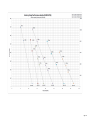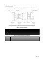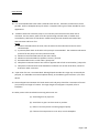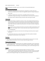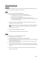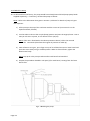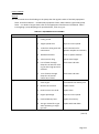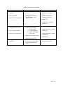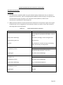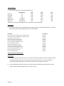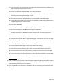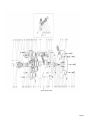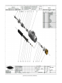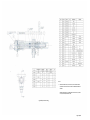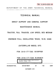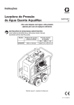
1
Part No. 061-357 HARBEN CENTURY TYPE PUMP MK 4D SERVICE MANUAL Issue 4: June 2014 Flowplant Group Ltd Gemini House, Brunel Road, Churchfields Industrial Estate, Salisbury, Wiltshire. SP2 7PU United Kingdom t: +44 (0)1722 325424 f: +44 (0)1722 411329 e: [email protected] HARBEN CENTURY TYPE PUMP SERVICE MANUAL CONTENTS FOREWORD HEALTH AND SAFETY AT WORK SAFETY CODE OF PRACTICE SECTION 1 PUMP TECHNICAL DATA SECTION 2 PUMP INSTALLATION SECTION 3 GENERAL OPERATING INFORMATION SECTION 4 PUMP MAINTENANCE AND OVERHAUL PROCEDURES SECTION 5 WARRANTY A detailed Contents list precedes each Section (i)/(ii) FOREWORD This manual is primarily concerned with the Harben Century Type Pump. In addition, general safety and operating information for the equipment into which the pump is installed is also included. The conversion of pressurised water into a high velocity jet and its use as a cleaning and cutting tool is now familiar to, and used by, many people in a wide range of industries. High pressure water can achieve remarkable results without the use of heat or chemicals and cost savings over conventional maintenance methods can in many cases show that a water jetting unit will pay for itself in hours rather than years. Many companies have problems for which high pressure water offers a rapid solution, yet hesitate to consider this method because of the generally accepted high cost of such equipment. Backed by many years of design and manufacturing experience, Harben pumps are setting new standards of performance and reliability. The capital and operating costs are such that these offer and attractive return on investment that really makes sense. Flowplant Group Ltd have a policy of continual research and improvement and we reserve the right to make such modifications and design changes as are considered necessary in the light of experience, however, this copy of the manual will not be amended. No part of this manual may be reproduced or copied in any manner without written permission from Flowplant Group Ltd. (iii) HEALTH AND SAFETY AT WORK There are two main categories of risk. These are: a) Injury from impact of water b) Injury from environment. All persons involved in water jetting should be made aware of the risks. INJURY FROM IMPACT OF WATER In the event that a person is injured by the impact of a water jet, the injury caused may appear insignificant and give little indication of the extent of the injury beneath the skin and the damage to deeper tissues. Large quantities of water may have punctured the skin, flesh and organs through a very small hole that may not even bleed. Immediate hospital attention is required and medical staff must be informed of the cause of the injury. To ensure that this is not overlooked, all operators engaged on jetting should carry an immediately accessible waterproof card which outlines the possible nature of the injury and bears the following text which has been endorsed by the Employment Medical Advisory Service (EMAS) of the Health and Safety Executive: THIS MAN HAS BEEN INVOLVED WITH HIGH PRESSURE WATER JETTING AT PRESSURE UP TO 36750 LB/IN2 (250 MPA, 2500 BAR, 2548 KG/CM2 ) WITH A JET VELOCITY OF 1536 MILES (2458 KM) PER HOUR. Please take this into account when making your diagnosis. Unusual infections with micro-aerophilic organisms occurring at lower temperatures have been reported. These may have gram negative pathogens such as are found in sewage. Bacterial swabs and blood cultures may therefore be helpful. A letter containing this and other relevant information should be sent to the doctor of each operator. Where surgical examination is not immediately possible in remote situations, first aid measures should be confined to dressing the wound and observing the patient closely until a medical examination has been arranged. If any person, object or article is accidentally struck by the jet, this fact must be reported to the operator's representative. (iv) INJURY FROM ENVIRONMENT Work should only be carried out if it is safe to do so. A thorough examination of the site should be carried out before work is started. Refer to the Warnings and Cautions. Special care should be taken where there is a danger of infection. There are many situations where infection can take place. As a guide to avoiding infection, the following points should be considered: a) Full protective clothing must be worn. b) Always clean scratches or cuts immediately. Disinfect and cover with a strip of gauze and impermeable plaster. SEEK MEDICAL HELP. c) Avoid rubbing eyes, nose or mouth with hands during working. d) All contaminated clothing, vehicles and equipment should be thoroughly cleaned. e) Operators should wash thoroughly after work and before eating, drinking or smoking. (v)/(vi) SAFETY CODE OF PRACTICE Full details of the Safety Code of Practice, when working with equipment containing a Harben pump, are given in Section 3 of this manual. The basic rules of this code are as follows: 1. ALWAYS WEAR THE CORRECT PROTECTIVE CLOTHING. 2. ALWAYS ENSURE ALL EQUIPMENT IS IN A FIRST CLASS CONDITION. 3. NEVER WORK FROM A LADDER. 4. NEVER USE THE GUN WITH THE TRIGGER LOCKED ON. 5. NEVER POINT THE GUN AT ANYONE, EVEN IF SWITCHED OFF. Only a responsible person who has received instruction in the operation of high pressure water jetting equipment should be allowed to operate the equipment. (vii)/(viii) SECTION 1 TECHNICAL DATA SECTION 1 TECHNICAL DATA CONTENTS Para Introduction 1 Pump description Function Filtration Fluid Flow Identity Manufacturer Pump Options/Identification Design and performance data Physical data Performance Characteristics Equipment Details Associated publications 4 9 10 11 12 15 16 17 18 ILLUSTRATION Fig 1.1 Page Harben Century Type High Pressure Pump 1.9 TABLES Table Page 1.1 Pump Physical data 1.5 1.2 Pump Performance Data - Maximum Working Pressures 1.5 1.3a/b Performance Data - Century Type Pump and HP Required 1.7a/b 1.3 1.8 Equipment Serial Numbers and Jet Sizes Pages 1.1/2 Page 1.3 TECHNICAL DATA INTRODUCTION 1. The Harben Century Type high pressure pump (Fig 1.1) is a radial piston diaphragm pump which can be used for a number of industrial applications, including the following: (a) (b) (c) (d) (e) (f) (g) (h) (i) (j) High pressure cutting of board, plastic and other materials Water hydraulic systems Abrasive blasting and de-scaling Drain/sewer cleaning Tube de-scaling Desalination by reverse osmosis Pumping demineralised water Floor and surface cleaning Underwater cleaning Surface preparation. 2. In addition to its reliability and long service intervals, the advantages of using this type of pump include: (a) Variable pressure and flow options without piston change (b) Pumps can run dry without damage as there are no piston seals (c) Filtration up to 150 microns (d) No modification is required to pump sea water (e) Pump has multi-cylinders therefore no pulsation 3. The pump is designed to be directly-coupled and flange-mounted, and can be supplied in either bare-shaft form, or skid mounted, trolley mounted, trailer mounted or truck mounted configurations. In addition, the pump can be mounted on an underwater ROV. Diesel drive, electrical drive and hydraulic drive options are available. PUMP DESCRIPTION Functional NOTE The following description of the Harben Century Type Pump applies equally to the 4 and 8 cylinder variants of the pump, Performance details of each type of pump are given later in this section. 4. The Century pump works on the radial piston design principle which uses one-way valves in conjunction with tubular diaphragms, fitted with an internal support or mandrel. The pumped fluid, which passes through this diaphragm, is enclosed by a cylindrical pressure chamber or barrel, in the ends of which are fitted inlet and delivery valves. 5. The pump crankcase, which contains the only mechanical moving parts, is filled with mineral hydraulic oil. This oil provides for the lubrication of all moving parts within the crankcase, and as a means of pressure to compress the diaphragm. Page 1.3 6. As the pump shaft rotates, the piston advances and its ports pass the end of the cylinder, sealing the chamber. Further advance of the piston causes the trapped oil to compress the diaphragm around the mandrel, expelling the water in the diaphragm through the delivery valve and into the delivery manifold. 7. When the piston retreats, the diaphragm reverts to its tubular form and draws water through the inlet valve. Any oil slippage past the piston during the delivery stroke is made up through the piston ports as they open to the crankcase oil. 8. All mechanical parts, with the exception of the inlet and delivery valves, run in the oil-flooded crankcase and are therefore unaffected by contamination by the pump fluid, or by running dry. Filtration 9. Standard filtration for the pump is normally 50 microns. This filter is usually fitted to the inlet of the supply tank or reservoir. This arrangement ensures that if the filter is neglected to the point of blockage, the tank will empty and the pump will run dry, thus enabling the dry-running qualities of the pump to be used as a filter maintenance indicator. Inlet conditions required are flooded suction; pressure feeding is not necessary. Fluid Flow 10. Arrangements are made on the pump for the incoming fluid to cool the crankcase oil. The use of standard diaphragm/barrel assemblies provides a choice of flows, depending upon the number of barrels fitted to a crankcase. The cylindrical form of these barrels is well suited to containing high pressures. Three piston diameters are available to suit a range of pressure up to 700 bar (10 000 psi). IDENTITY Manufacturer 11. The Harben Pumps are manufactured by: Flowplant Group Ltd., Brunel Road, Churchfields, Salisbury, Wiltshire, SP2 7PU ENGLAND. Tel: +44 (0)1722-325424 Fax: +44 (0)1722-411329 Pump Options/Identification 12. The Century Pump is available in either 4 or 8 cylinder options, with each having a choice of piston/cylinder diameter options of 22.5 mm, 25.0 mm or 27.5 mm. 13. All barrels are given a letter code to indicate their position in the crankcase (refer to Section 4, Fig 4.2). This letter code can be found stamped on the face adjacent the inner cylinder. Letters A to H are used. Each barrel of a different code is given its own part number. Page 1.4 14. A pump specification label is fitted on the pump crankcase, adjacent to the oil filler cap. This label will give the pump type, ie number of cylinders and piston/cylinder diameter. For example: 8 no. of cyl 22.5 piston/cyl dia. The label also gives the pump serial number, the type of oil to be used (Shell Tellus or equivalent), the maximum working pressure, the maximum working flow, and the pump's year of manufacture. DESIGN AND PERFORMANCE DATA Physical Data 15. TABLE 1.1 PUMP PHYSICAL DATA Pump diameter Pump length Inlet Outlet Shaft diameter Shaft length 560 mm 451 mm 2 in BSP/50 mm dia. hose tail 1 /2 in BSP 45 mm 83 mm NOTE For full details of the pump physical data refer to Fig 1.1. Performance Characteristics 16. For full details of the Century Series, Pump performance data, reference should be made to the appropriate information given in Tables 1.2 and 1.3a/b. TABLE 1.2 PUMP PERFORMANCE DATA - MAXIMUM WORKING PRESSURES Pump/Cylinder Diameter 22.5 mm 25.0 mm 27.5mm 1000 rpm (normal working speed) 10 000 psi (700 bar) 8000 psi (550 bar) 6000 psi (415 bar) NOTES 1. As a rule electrically-driven and diesel-driven pumps run at 1000 rpm, nominal. 2. Quantity of cylinders does not, alter pump working pressure. 3. Quantity of cylinders does alter flow rate. Page 1.5 EQUIPMENT DETAILS 17. Details relevant to the pump and associated equipment should be entered on the form shown in Table 1.3, at the rear of this section, for future reference. ASSOCIATED PUBLICATIONS 18. Associated with this manual are the following publications: Operators guide Code of practice Page 1.6 - Part no. 061-225 Part no, 057-062 Page 1.7a Page 1.7b Page 1.7b Page 1.7b Pump Type Pump Serial No(s) Engine Type Engine Serial No Gearbox Type Gearbox Serial No Motor Frame/kW Motor Serial No Maximum Working Pressure of Pump Maximum Flow at Above Pressure Single Gun High Velocity Jet Size Single Gun 15 Degree Fan Jet Twin Gun High Velocity Jet Size Twin 15 Degree Fan Jet Size Twin Gun Choke Size Type of Safety Gun Supplied High Efficiency Drain Jets 3 Rear HE drain jet 6 Rear HE drain jet 3 Rear 1 forward HE drain jet Bomb/Ram Jet HV Turbo/Dia 38 mm Screma Jet Fan Dia 16 mm Screma Jet Jet Leader Plough Jet Jet Pump Type Jet Sizes Rotoblast Hovervac This pump unit and all the accessories listed above have been tested at: bar psi Page 1.8 Fig 1.1 Harben Century Type High Pressure Pump Page 1.9/10 SECTION 2 PUMP INSTALLATION SECTION 2 PUMP INSTALLATION CONTENTS Para Introduction Pump Mounting General Details Pump Fitting Coupling Arrangements 1 3 8 9 Inlet Water General 10 ILLUSTRATIONS Fig 2.1 2.2 Page Pump Installation - Water Circuit Layout Pump Installation - Prime Mover/Gearbox/Pump Coupling Arrangements 2.3 2.5 TABLES Table 2.1 2.2 2.3 2.4 2.5 Page Century Gearboxes Coupling for Century Gearboxes Flywheel Couplings Perkins/Ford Motor Half Couplings for Electric Motors Bell Housings 5 5 6 6 6 Page 2.1/2 PUMP INSTALLATION INTRODUCTION 1. It may be the case that the pump has not been purchased as part of a trailer or skid. The information given in this section is intended to enable customers to install the pump package in a frame of their design. It will enable engineers to carry out preliminary design work before submitting the design for Flowplant Group approval. Refer to Section 1 for technical data and a description of the pump. Section 1, Fig 1.1 should be referred to for further technical details and installation data. 2. The illustration given in Fig 2.1 Century Series pump. Fig 2.1 Pump Installation – Water Circuit Layout Page 2.3 PUMP MOUNTING General Details 3. The Century Series pumps are designed for direct drive and flange mounting. The normal operating speed is 1000 rpm, nominal. Maximum operating speed is 1200 rpm. The pump must rotate anticlockwise, looking at the front of the pump ('arrow' cast into crank- case). The maximum inlet water pressure for the pump is 0.5 bar (5.0 metre head), whilst the maximum oil pressure for the pump is 4.0 metre head to centre line of pump. 4. The pump can be inclined between horizontal and 45 degrees (delivery end uppermost). If further inclination is required, between 45 degrees and vertical, Flowplant Group Ltd should be contacted at the address given in Section 1. 5. The weight of a pump with oil in the crankcase, drive coupling fitted and bell housing, depends on the number of cylinders fitted, as follows: 4 cyl - 160 kg 8 cyl - 205 kg 6. The engineer should ensure that all couplings are fitted with a 3 mm clearance. Where a bell housing (pump mounting and coupling shaft and cover) cannot be fitted due to a difference in spigot or bolt locations, an adaptor ring may be fitted. Refer to Para 9 for further details of coupling arrangements. 7. It is recommended that a detailed layout be drawn and the following points considered: (a) Selection of bell housing most suitable for adaptor ring. Additional machining to the bell housing may be required. (b) Sufficient coupling engagement on the shaft whilst maintaining the recommended clearance. (c) Clearance between shafts; careful design can eliminate the shortening of motor/engine shaft. Pump Fitting 8. When the pump is to be fitted in position, the following points should be noted: (a) When the pump is first married up to the prime mover, access is required to check coupling clearance. When Flender B200 couplings are used, sight/gauge holes are drilled in the bell housing for this purpose. (b) It depends on the particular installation whether the pump head is removed to a workshop for maintenance, eg diaphragm or valve replacement or whether work is carried out in-situ. (c) Where a pump 'strip-down' is required, the pump should be removed to the workshop. The use of an assembly stand (part no 100-279) is recommended. Page 2.4 Coupling Arrangements 9. For details of the prime mover/gearbox/pump coupling arrangements for diesel-driven and electrically-driven pumps, refer to Fig 2.2 and Tables 2.1 to 2.5. Fig 2.2 Pump Installation – Prime Mover/Gearbox/Pump Coupling Arrangements TABLE 2.1 CENTURY GEARBOXES PART NO 105-119 105-120 105-121 105-125 DESCRIPTION 2.7:1 Gearbox Bare Shaft Century 2.25:1 Gearbox Bare Shaft Century 2.0:1 Gearbox Bare Shaft Century 1.86:1 Gearbox Bare Shaft Century TABLE 2.2 COUPLING FOR CENTURY GEARBOXES PART NO 100-342 100-366 023-594 DESCRIPTION Output Coupling B200 Pt 1, Flex Bore 57 mm, Key 16 mm Input Coupling B180 Pt 1, Flex Bore 45 mm, Key 14 mm Perkins 1000 Series Input Coupling M200 - Iveco 7000 Series Page 2.5 TABLE 2.3 FLYWHEEL COUPLINGS PERKINS/FORD PART NO 100-633 100-367 023-593 DESCRIPTION Coupling PT10 E180 CF - Perkins T6354.4/1006TG Coupling PT10 E180 CF - Ford 2726T Coupling PT10 E200 - Iveco 7675Si TABLE 2.4 MOTOR HALF COUPLINGS FOR ELECTRIC MOTORS (Metric Frame - Non-hazardous Types) PART NO 100-487 100-487 023-304 023-304 023-304 023-304 DESCRIPTION 37 kW/50 HP Motor Coupling B200 Pt 1 45 KW/60 HP Motor Coupling B200 Pt 1 55 KW/75 HP Motor Coupling B200 Pt 1 75 KW/100 HP Motor Coupling B200 Pt 1 95 kW/125 HP Motor Coupling B200 Pt 1 111 kW/150 HP Motor Coupling B200 Pt 1 TABLE 2.5 BELL HOUSINGS PART NO 100-084 100-082 100-329 012-186 Page 2.6 DESCRIPTION Diesel, Century Bell Housing Bell Housing 37 kW - 111IkW, Electric Adaptor Ring - must be used on 75 - 111kW electric motors Adaptor Ring - must be used on diesel engines INLET WATER General 10. It is recommended that inlet water is filtered to 50 microns. Filtration to 150 microns is also possible. Refer to Flowplant Group for advice. Flowplant offer types of filter suitable for most applications. 11. Turbulent water will cause the pump to run unevenly and cause excessive wear due to cavitation. For this reason, water must first pass through a break water or header tank controlled by a ball valve or float device. Water leaving the tank should have lamina flow characteristics and be air free. NOTES 1) If water is filtered before the tank, then the tank must be sealed and vented to avoid contamination. 2) A pressure/flow check at the inlet to the pump is recommended. The maximum inlet water pressure for the pump is 0.5 bar (5.0 metre head). 3) Minimum recommended 0.05 bar (0.5 metre head) 4) Minimum recommended inlet speed o.5 metres / second. 5) Recommended vortex in tank outlet / pump inlet 6) Flowplant recommend return line to be on opposite side of tank to tank outlet / pump inlet. 7) Flowplant recommend that tank should be of sufficient size so that at full flow, cannot be drained in under 4 minutes. 12. A pH value of 5 to 9 is recommended. Although liquids outside this range may occasionally be pumped, it is advisable to contact Flowplant Group, at the address given in Section 1, for their advice. 13. Hose and pipe bores between the break water tank and pump should be a minimum of 50 mm (2 in) and up to a length of 1 metre. If a longer length of hose/pipe is required, refer to Flowplant. 14. Other points to be considered concerning inlet water are: (a) Avoid long hose or pipe runs. (b) Avoid hose or pipe runs that cause air pockets. (c) Refer to circuit layout for mounting angle of pump. (d) If water inlet temperature is over 30°C, consult Flowplant. Page 2.7/8 SECTION 3 GENERAL OPERATING INFORMATION SECTION 3 GENERAL OPERATING INFORMATION CONTENTS Para Introduction Safety Code of Practice General Safety Gun Drain/Sewer and Pipe Cleaning Hoses Underwater Recoil-less Safety Gun Tube Cleaning Hoverclean Abrasive Injection Equipment Accidents Protective Equipment 1 2 5 6 7 8 9 10 11 12 13 14 General Operating Instructions Introduction Starting Stopping To Oil Bleed the Pump To Water Bleed the Pump To Anti-Freeze a Unit Without an Anti-Freeze Tank To Remove Anti-Freeze From a Unit Without an Anti-Freeze Tank To Anti-Freeze a Unit With an Anti-Freeze Tank Fitted To Remove Anti-Freeze From a Unit With an Anti-Freeze Tank Fitted 15 16 17 18 19 20 21 22 23 Fault finding General 24 ILLUSTRATIONS Fig 3.1 3.2 Bleeding the Pump Pump Fault Finding - Diaphragm Failures and Indications of Other Problems Page 3.8 3.14 TABLE Table 3.1 3.2 Equipment Fault Finding Pump Fault Finding Page 3.11 3.13 Page 3.1/2 GENERAL OPERATING INFORMATION INTRODUCTION 1. This section gives general information on safety, protective clothing to be used by operators, and general starting and stopping procedures when the pump is incorporated in a machine. It should be remembered that the operating procedures given are to be used as a guide only, and the equipment handbook operating procedures should be used where applicable. SAFETY CODE OF PRACTICE BASIC RULES 1. 2. 3. 4. 5. 2. ALWAYS WEAR THE CORRECT PROTECTIVE CLOTHING. ALWAYS ENSURE ALL EQUIPMENT IS IN A FIRST CLASS CONDITION. NEVER WORK FROM A LADDER. NEVER USE THE GUN WITH THE TRIGGER LOCKED ON. NEVER POINT THE GUN AT ANYONE, EVEN IF SWITCHED OFF. This Code of Practice is intended to provide guidance on the safe operation of high pressure water jetting equipment. 3. The term 'high pressure water jetting' covers all water jetting, including the use of additives and abrasives, where there is an energy input to increase the pressure of water. 4. This code applies to high pressure water jetting as defined above where there is a foreseeable risk of injury. General 5. 1) Only a responsible person who has received instruction in the operation of high pressure water jetting equipment should be allowed to operate the equipment. 2) Barriers should be erected around the cleaning bay or where the work is being done 'in-situ', round the section of plant concerned. Access within 10 metres by persons other than the jetting team, is strictly prohibited. 3) A warning notice 'NO UNAUTHORISED ENTRY High Pressure Water Jetting in Progress' should be displayed on each side of the bay, or on the plant, where the work is to be done. 4) Each member of the team should be provided with suitable waterproof clothing, wellington boots with internal steel toe caps, safety helmet with visor and ear defenders, and gloves. Refer to Para 14 for details of protective clothing available. Page 3.3 SAFETY CODE OF PRACTICE (Cont'd) General (Cont'd) 5) Never attempt to change jets or accessories whilst the pump is operating, even if the flow control selector valve is in the recycle (dump) position. Safety Gun 6. 1) Never point the safety gun at anyone, even if it is switched off. 2) When using the 'dead-mans handle' safety gun, the required jet should befitted to the high pressure barrel (low pressure barrel is fitted with a diffuser) and tightened correctly before starting the unit. All other hose connections, etc must be checked before attempting to start the unit. 3) Water jetting guns should be properly maintained and care should be taken not to damage the delicate components of the trigger mechanism. Drain/Sewer and Pipe Cleaning 7. 1) In addition to the protective clothing listed in Para 5(4), the other equipment should be used when entering confined spaces, such as safety harness and rescue line, atmospheric testing equipment, escape breathing apparatus and hand lamps (intrinsically safe where appropriate). 2) To prevent snaking or reverse travel of a flexible hose inside the tube being cleaned, a section of steel pipe, slightly longer than the diameter of the tube to be cleaned, should be connected between the flexible hose and the nozzle (drain jet extension). 3) During drain cleaning operations it is advisable to use a coloured leader hose to act as a warning to the operator that the hose recovery is almost complete. 4) Where drain or pipe jetting operations are to be carried out remote from the high pressure pump unit, i.e. where communication between the person controlling the pump and the equipment operator is not possible, it is essential that a remote control kit or foot control valve is used at the work point. Hoses 8. 1) Care should be taken to ensure that all hoses are maintained in good condition and are of the correct specification for the pressure being used. 2) Never loop the hose into an excessively tight radius, particularly adjacent to couplings. 3) When fitting re-usable couplings, always ensure that the current type of couplings are being used in relation to the hose specification. Page 3.4 SAFETY CODE OF PRACTICE (Cont'd) NOTE The equipments detailed in Paras 9, 10, 11 and 12 are for specialist applications. Underwater Recoil-less Safety Gun 9. 1) The Harben Underwater Recoil-less Safety Gun is designed for use under-water only. Extreme care should be taken to avoid rear-facing balance jetswhen testing the equipment above water. 2) If working in shallow water, where there is a possibility of the diver surfacing inadvertently during water blasting, care should be taken to ensure that the recoil balance jet protection tube is sufficiently long to prevent the diver directing it at himself. Tube Cleaning 10. 1) Where tube cleaning is to be done by means of a lance, the chargehand who operates the remote control valve should first insert the lance into the tube, leaving the other end of the lance supported by one man. Once the tube has been inserted, the other men required to support the control lance should take up their places, and only then should the chargehand operate the valve. NOTE When the person operating the remote control valve is unable to speak directly to the man, or men, controlling the lance, a clearly understood system of signals and instructions must be agreed upon. 2) A barrier should be placed at the far end of the tube being cleaned for protection against flying debris. 3) A shield fitted to the lance to protect the operator from debris ejected by backward pointing jets should be used for certain operations. Hoverclean 11. 1)The angle of the jet holders determine the rotational speed of the spray bar; this is set and locked in position at the works, and on no account must this angle be altered. Abrasive Injection Equipment 12. 1) Because water/abrasive jetting can give rise to dangerous splash back, ensure all protective clothing, detailed in Para 5(4), is used. Some abrasives are known to produce residues which may be serious to health and should not be used for blasting, such as sand containing free silica. Accidents 13. 1) In the event of a person being injured by the impact of a water jet, the injury caused may appear insignificant and give little indication of the extent of the injury beneath the skin and the damage to deeper tissues. Large quantities of water may have punctured the skin, flesh and organs through a very small hole that may not even bleed. Page 3.5 SAFETY CODE OF PRACTICE Accidents (Cont'd) (Cont'd) 2) Operators should carry a card which explains to medical staff the possible nature of the injury, both relating to the high pressure water and any unusual infections that may be found in sewage, such as leptospirosis, better known as Weil's Disease. PROTECTIVE EQUIPMENT 14. A range of top quality protective equipment is available from Flowplant Group Ltd, as follows: PART NO. DESCRIPTION BRITISH STANDARD 061- 037 061- 025 061- 026 061- 020 Suit Waterproof Orange size small Suit Waterproof Orange size medium Suit Waterproof Orange size large Suit Waterproof Orange size extra large BS4170 BS4170 BS4170 BS4170 065- 029 065- 016 065- 017 065- 018 065-019 065- 002 Boots Wellington size 7 Boots Wellington size 8 Boots Wellington size 9 Boots Wellington size 10 Boots Wellington size 11 Boots Wellington size 12 BS1870 BS1870 BS1870 BS1870 BS1870 BS1870 065- 004 065- 027 065- 006 065- 005 065- 029 065- 013 065- 021 Gloves Helmet Visor Visor and Chin Guard Ear Defenders Helmet White Visor and Chin Guard Ear Defenders Harness Safety/Rescue BS1651 BS5240 BS2092 BS2092 BS5108 BS5240 BS2092 BS5108 BS1397 065- 025 057- 059 065- 028 Sign Warning 'WATER JETTING' Sign Safety Warning (adhesive) Cone Traffic 450 mm 065- 023 065- 022 065- 024 Detector Gas BASEEFA Approved Torch BASEEFA Approved Breathing Apparatus 15 minute Escape Set 061-257 057- 062 Operators Safety Guide Safety Code Of Practice Page 3.6 GENERAL OPERATING INSTRUCTIONS Introduction 15. The following operating instructions are of a general nature with reference being made to the appropriate manufacturer's handbook for the machine. Starting 16. To start the unit, carry out the following instructions: 1) Prior to starting the unit, carry out the following pre-checks: i. Set the high pressure selector to the recycle (dump) position. ii. Ensure the unit is on level ground. iii. Check that the water supply is connected and the header tank is full. iv. Check that all guns and nozzles are connected. Ensure correct fitting and correct size for the pressure required. 2) Start the unit. Refer to the manufacturer's handbook for information concerning engine/electric motor starting procedure. NOTE Before starting the unit and carrying out water and/or oil bleed operations (refer to Paras 18 and 19, respectively), familiarise yourself with the units controls and the stopping instructions (Para 17). 3) Move the selector to the High Pressure position. 4) Increase engine rpm (if diesel) to achieve desired pressure. Stopping 17. To shut down the unit, carry out the following instructions: 1) Reduce engine revs to tick-over speed. 2) Move the high pressure selector to the recycle (dump) position. 3) Switch off the prime mover by following the instructions given in the manufacturers and book for the engine/electric motor. 4) If there is the risk of freezing, follow the instructions given the frost precautions (antifreeze procedures, Paras 20 or 22). 5) If the unit is to be stored for more than 7 days without running, an inhibitor should be run through the system. Do not drain prior to storage; always leave full of fresh water or inhibitor. 6) Refer to the manufacturer's handbook for information concerning engine/ electric motor protection/storage. Page 3.7 To Oil Bleed the Pump 18. As delivered from the factory, the pump would have already been oil bled (except pump heads supplied separately). If necessary, oil bleed the pump as follows: NOTE Refer to the lubrication chart given in Section 4, Table 4.2 for details of pump oil types and capacities. 1) Fill the pump to the top of the crankcase with the correct oil (or ensure oil is in the expansion bottle, if fitted). 2) Set the selector valve to the recycle (dump) position and start the engine/motor. Run at 750 rpm tick-over to prime, or inch electric motor (on/off). NOTE If the unit is fitted with a shut-down protection device, hold in the override button for 10 seconds (this allows the engine oil pressure to build up). 3) With reference to Fig 3.1, put a finger on top of an oil bleed screw on a lower barrel and open the screw slowly using a suitable spanner. When air-free oil flows, tighten the bleed screw firmly. NOTE Top up oil in the pump crankcase after each barrel has been bled. 4) Repeat the procedure detailed in sub-para (3) for each barrel, starting from the lower barrels first. Fig 3.1 Bleeding the pump Page 3.8 5) When the operator has taken up a working position, move the selector lever to the High Pressure position and increase engine speed to reach working pressure. 6) If the delivery line vibrates or the pump does not run smoothly, stop the unit and carry out a water bleed (Para 19) and then repeat the oil bleed. To Water Bleed the Pump CAUTION ON NO ACCOUNT OPEN THE WATER BLEED SCREWS WHEN THE PUMP IS OPERATING UNDER PRESSURE. 19. Whenever the unit is started after being allowed to run dry, the following procedure must be followed: 1) Set the selector valve to the recycle (dump) position and start the engine/motor. Run at 750 rpm tick-over to prime, or inch electric motor (on/off). NOTE If the unit is fitted with a shut-down protection device, hold in the override button for 10 seconds (allows engine oil pressure to build up). 2) The pump is self-priming. If, however, any difficulty is experienced, stop engine, loosen the upper bleed nipples and allow water to flow from each nipple (ensure that the header tank remains full). Tighten nipples and repeat the procedure detailed in sub-para (1). To identify the bleed nipples, refer to Fig 3.1. 3) When the operator has taken up a working position, move the selector lever to the High Pressure position and increase engine speed to reach working pressure. NOTE If the delivery line vibrates this indicates that air is still in the system. Stop the unit and repeat the procedure detailed in sub-para (1) . To Anti-Freeze a Unit Without an Anti-Freeze Tank 20. 1) Prepare 5 gallons (or larger quantity if required) of 30% to 50% anti-freeze solution. 2) Drain the water tanks. 3) Pour the anti-freeze solution into the break tanks. 4) Remove any jet or accessory from the end of the high pressure hose. 5) Ensure the high pressure selector lever is in the dump (or off) position. Start the engine and allow to run for 1 minute. 6) Holding the outlet end of the hose, move the selector to high pressure position and allow the engine to run until the anti-freeze solution can be seen coming from the high pressure hose. 7) Stop the engine. The unit is now anti-freezed. Page 3.9 To Remove Anti-Freeze From a Unit Without an Anti-Freeze Tank NOTE During this procedure, carry out the air bleed procedure detailed in Para 19, if necessary. 21. 1) Drain any anti-freeze solution from break tanks into a container. 2) Fill break tanks with water. 3) Place the outlet of the high pressure hose into the container. 4) Place the selector lever in the high pressure position, and whilst holding the high pressure hose, start the engine. 5) Run the engine until all solution is returned to the container and clean water is seen flowing from the hose. The unit is now ready to use. To Anti-Freeze a Unit With an Anti-Freeze Tank Fitted 22. 1) Ensure the anti-freeze tank is full of 30% to 50% anti-freeze solution. 2) Turn the 3-port valve to the anti-freeze position and open valve on the anti-freeze tank (if fitted). 3) Remove any jet or accessory from the end of the high pressure hose. 4) Move the selector lever to the high pressure (or on) position. 5) Holding the end of the hose, start the engine. 6) Allow engine to run on tick-over until the anti-freeze solution can be seen coming from the high pressure hose. 7) Move the selector to the recycle (dump) position for 5 seconds (this allows the dump hose to be anti-freezed). 8) If Jump Jet or Remote Control kits are fitted, ensure they are anti-freezed. The unit is now anti-freezed. To Remove Anti-Freeze From a Unit With an Anti-Freeze Tank Fitted 23. 1) Move the 3-port valve to the water position. 2) Fill the water tanks. 3) Place the outlet of the high pressure hose into the anti-freeze tank. 4) Place the selector lever in the high pressure position. 5) Start the engine. Allow it to run at tick-over and pump anti-freeze solution into the antifreeze tank. Stop the engine when clear water is seen flowing out of the high pressure hose. The unit is now ready to use. Page 3.10 FAULT FINDING General 24. It is essential when fault finding on the pump that due regard is taken of the likely equipment faults. Therefore Table 3.1 includes likely equipment faults, whilst Table 3.2 gives likely pump faults. For details of engine faults refer to the appropriate manufacturer's handbook. When investigating a pump diaphragm for possible failure, refer to Fig 3.2. TABLE 3.1 EQUIPMENT FAULT FINDING Problem Low System Pressure High System Pressure Cause 1. Worn or incorrect size of cutting nozzle. Action Replace nozzle. 2. Engine speed slow. Adjust to correct speed. 3. Leaks from hose,pipes and connections. Check connections for tightness. Replace as necessary. 4. Blocked inlet filter. Clean or replace element. 5. Inlet hose too long. Shorten hose length. 6. Loss of water through dump line of selector valve or gun when high pressure selected. Check seats and seals. 7. Loss of water through dump line of remote control kit, if fitted. 1. Blocked nozzle, selector valve or gun. Check seats and seals. 2. Nozzle size too small. Replace nozzle. 3. Hose bore size too small. Replace hose. 4. Engine speed high. Adjust to correct speed. 5. Crushed delivery hose. Replace if necessary. 6. Two gun choke left in gun when operating as single gun unit. Replace with STD choke. Clean nozzle, selector valve or gun and flush out delivery line. (Cont'd) Page 3.11 TABLE 3.1 EQUIPMENT FAULT FINDING (Cont'd) Problem Low Water Level Pump Not Running Evenly (also refer to Pump faults). Burst Disc Failure or Safety Relief Valve Operating (also refer to high system pressure problem). Page 3.12 Cause 1. Blocked or dirty pre-filters. Action Clean or replace elements. 2. Faulty ball valve assembly. Replace if necessary. 3. Wrong seat in float valve assembly. Replace if necessary. 4. Low inlet pressure. 1. Air in water. Increase pressure. Water bleed pump (Para 19). 2. Air in crankcase oil. Oil bleed pump (Para 18). 3. Worn Coupling. Replace flexible elements and examine coupling. 4. Faulty inlet or delivery valve. Check valve condition. 5. Diaphragm protection valve. Re-seat protection valve and check delivery valves for ware/damage 1. Incorrect burst disc. Replace with correct disc. 2. Incorrect valve setting. Check certificate/setting. 3. Faulty valve. Repair or replace, as necessary. 4. Faulty or fatigued burst disc. Replace with new disc. TABLE 3.2 PUMP FAULT FINDING Problem 1. Mixing of Oil and Water in Crankcase. Cause 1. Worn or damaged delivery valves. Action 1. Check all delivery valves replace as necessary. 2. Loss of pressure. 2. Damaged filter element allowing debris to jam delivery valve. 2. Check all diaphragms replace as necessary 3. Pump not running evenly. 3. Replace oil. 4. Check filters - replace as necessary. 1. Loss of crankcase oil through pressure hose. 2. Loss of pump pressure 3. Pump not running evenly 1. Inlet restriction may have been caused through; a. Blocked filters b. Kinked inlet hose c. Worn or damaged inlet valve 1. Clear restriction 2. Check inlet valves – replace if necessary. 3. Check diaphragms – replace as necessary. 2. Excessive inlet hose length 4. Replenish oil. 1. Mixing of Oil and Water in Crankcase 3. Pump has been frozen 1. Diaphragm failure (may have been through fatigue from excessive running hours) 1. Check all diaphragms – replace as necessary. Page 3.13 Fig 3.2 Pump Fault Finding – Diaphragm Failure and Indication of Other Problems Page 3.14 SECTION 4 PUMP MAINTENANCE AND OVERHAUL PROCEDURES SECTION 4 PUMP MAINTENANCE AND OVERHAUL PROCEDURES CONTENTS Para Routine Maintenance Introduction Pump Service Information General Recommended Service Tools Torque Settings Service Kits Pump Overhaul Procedures Introduction Removal and Replacement of Pump Head Removal and Inspection of Delivery Valves - 4 Cylinder Pumps Removal and Inspection of Delivery Valves - 8 Cylinder Pumps Removal and Inspection of Delivery Valves - 4 Cylinder Pumps with Split Delivery Manifold Removal and Inspection of Inlet Valve Assembly and Diaphragm Separating Crankcase Halves Renewing Crankcase Components Re-Assemble Pump Pump Running In 1 3 4 5 6 7 9 10 11 12 13 15 17 23 24 ILLUSTRATIONS Fig 4.1 4.2 4.3 4.4 4.5 4.6 4.7 4.8 Mandrel Assembly Inlet Valve Seat - Back Up Ring and '0' Ring Fitting Barrel Code Century Pump - Assembly Century Pump - Barrel Assembly Century Pump - Parts List Selector Mk 2 - Century Safety Valve Assembly Page 4.11 4.12 4.18 4.21 4.23(a/b) 4.25 4.27 4.29 TABLES Table 4.1 4.2 Pump Maintenance Schedule Pump Lubrication Chart Page 4.3 4.4 Page 4.1/2 PUMP MAINTENANCE AND OVERHAUL PROCEDURES ROUTINE MAINTENANCE Introduction 1. The Maintenance Schedule (Table 4.1) gives details of pump maintenance only. For details of equipment maintenance, refer to the appropriate handbook. Details of pump oil capacities and recommended oil types are given in the Lubrication Chart (Table 4.2). Refer to the manufacturer's handbook for diesel engine oil. 2. Whilst specific periods for routine (preventive) maintenance of the pump are given, due regard should be taken of local regulations concerning the vehicle or machine. Ensure the machine is operating within those regulations. TABLE 4.1 CHECKLIST Crankcase oil PUMP MAINTENANCE SCHEDULE TO USE/DAILY/AFTER 8 HOURS RUNNING Check for level, fill if necessary (refer to Section 3, Para 18(1) for procedure and Table 4. 2 for oil types). Pipes, hoses and fittings Check wear, damage, correct rating and size. Pump working pressure Check correct. General Check pump for smooth running, overheating, leaks, and security of components. Inlet/delivery valves SIX MONTHLY/300 HOURS Check for wear and damage. Torque inlet nuts to 6001bft/82.9kgm/814Nm at 250 hours Diaphragms Check for wear and damage. Crankcase oil YEARLY/500 HOURS Drain and renew. Inlet/delivery valves Check for wear and damage. Pipes, hoses and fittings Carry out detailed inspection Inlet/delivery valves Replace Diaphragms Replace TWO YEARLY/1000 HOURS Page 4.3 TABLE 4.2 PUMP LUBRICATION CHART Manufacturer ESSO GULF MOBIL ROC TEXACO BP AGIP SHELL CENTURY OIL PETROFINA CASTROL Page 4.4 Type Nuto H150 LP 150 DTE Extra Heavy Kiron 150 Rando HD 150 Energol HLP 150 OSO 105 Tellus 150 PWLM Hydran 51 Hyspin AWS 150 Oil Capacity (litres) Number of Cylinders 4-cyl 8-cyl 13.0 11.0 PUMP SERVICE INFORMATION General 3. The following paragraphs give details of recommended service tools, torque settings, and service kits to be used when carrying out pump overhaul procedures. Recommended Service Tools 4. The following tools should be available when servicing the pump: Description Repair stand Driftmandrel, Separatormandrel, Driftinlet valve guide, Dolly, mandrel into diaphragm Driftvalve removal, Puller coupling and C balance Dolly, bearing crankcase Dollyeccentric, Dollyoil seal in, Dollyoil seal out, Dollyseal stretcher Dollyseal pusher, Dollyseal shrinker, Press (small) Wrench, hex 1/2" square drive, 8 mm x 100 mm Plierslong nose, 5", Torque wrench, Norbar No. 4 Screwdriver,flat blade,10" Hammer, nylon. 1 3/4" dia. Hammerlump,2 kg Spanner, adjustable, 6" Spanner, adjustable, 12" Spanner, adjustable, 15" Spanner, combination, 4 BA Spanner, slogging, 50 mm Spanner, slogging, 70 mm Spanner, open ended, 13 mm x 17 mm Spanner, open ended, 9/16" whit. x 5/8" whit. Spanner, plate, 61.3mm AF Socket, 3/4" square drive, 70 mm Socket, 3/4" square drive, 50 mm Socket, 1/2" square drive, 17 mm Socket, 1/2" square drive, 27 mm Socket, 1/2" square drive, 1116" Socket, 1/2" square drive, 5/16" Socket, converter, 1/2" F to 3/4" M Socket, reversible ratchet, 1/2" square drive Socket, extension bar 250 mm, 1/2" square drive Bucket, 15 litre Part Number 100-279 201-043 201-082 201-044 201-012 061-045 201-081 201-011 201-001 201-003 201-004 201-061 201-065 201-066 201-083 203-230 205-021 203-257 206-201 206-001 206-010 202-304 202-302 202-301 202-150 202-264 202-266 202-010 202-048 201-151 203-283 203-282 203-170 203-180 203-129 203-204 203-252 203-242 203-247 206-104 Page 4.5 Torque Settings 5. The torque settings for selected components are: Drg Item No* lbft kgm Inlet nut 43 600 82.9 Shaft bolt 92 100 13.8 Cylinder 25 500 69.1 Banjo bolt 57 and 58 120 16.6 Delivery nut 49 and 51 250 34.5 Banjo nut 107 and 106 200 27.6 *Refer to Para 8 and the drawings in this section to locate Item Number. Nm 814 135 680 160 340 270 Service Kits 6. Service/overhaul kits are available when carrying out repair or overhaul of the pump. Details of kits for the Century type pumps/accessories are as follows: Description Kit Overhaul, Valve and Diaphragm, 4 cyl Mk 4 Century Kit Overhaul, Valve and Diaphragm, 8 cyl Mk 4 Century Kit Seal, Mk 2 Century Selector Kit Overhaul, Mk 2 Century Selector Kit Overhaul, Mk 1Safety Relief Valve Kit Overhaul, Mk 2 Safety Relief Valve Kit Seal, Mk 9B Gun and FCV Kit Overhaul, Mk 9B Gun and FCV Kit Seal, Century Trigger Assembly Kit Overhaul, Century Trigger Assembly Kit Overhaul, High Speed Rotary Joint Kit Seal, High Speed Rotary Joint Kit Overhaul, Multi-selector Part Number 024-032 024-033 024-021 024-022 024-023 024-044 024-035 024-036 024-047 024-048 024-030 024-031 024-042 PUMP OVERHAUL PROCEDURES Introduction 7. During the pump overhaul procedures, reference should be made to the pump component and assembly drawings (Figs 4.1 to 4.6), which include associated parts lists, Also included are assembly drawings of the Mk 2 selector and safety relief valve (Figs 4.7 and 4.8). 8. In the following overhaul procedures, the item number that follows the description of a part refers to the assembly drawings (Figs 4.1 and 4.3 to 4.6). Page 4.6 Removal and Replacement of Pump Head NOTE Refer to Para 8 for drawing information. 9. Carry out a removal and replacement of the Pump Head, as follows: 1) Switch off and isolate the prime mover. 2) Switch off or disconnect the water mains supply to the tank. 3) Drain the water tank. 4) Disconnect the water inlet hose to the pump. 5) Disconnect the small bleed hose at the top of the Inlet Manifold, if fitted. 6) Disconnect the high pressure hose from the Delivery Manifold. 7) Drain water from the Inlet Manifold. 8) Disconnect the hose snap coupling from the top of the Crankcase to Oil Expansion Bottle. 9) Remove the hose from the top of the Crankcase, and replace with a Lifting Eye (114). 10) Connect lifting tackle to the Lifting Eye. Do not take the weight of the pump, leave only slack cable. 11) Remove the bolts from the bell housing, and pull off pump and bell housing. NOTE If an adaptor ring is fitted, it is usually best to leave it attached to the prime mover. 12) Before replacing the pump, check the drive coupling stand-off distance. 13) Replace the pump, generally reversing the removal procedure. NOTE Before operating the pump, it may be necessary to bleed the pump of air. 14) If the pump fitted is new or has been overhauled, carry out the running in procedure detailed from Para 15. Removal and Inspection of Delivery Valves - 4 Cylinder Pumps NOTES 1) Oil need not be drained. 2) Refer to Para 8 for drawing information. 10. Carry out removal and inspection of Delivery Valves, as follows: 1) Unscrew and remove the four Nuts (107 - not shown on drawings). Page 4.7 2) Lift off Washers (91 - not shown on drawings). 3) Delivery Tubes (19 - not shown on drawings) and Banjos (22 and 23) can now be pulled off. 4) Unscrew and remove Delivery Nut (51) containing the Valve Assembly. 5) Insert a flat blade screwdriver into the radial groove of Delivery Seat (45) and levering gently around, ease Seat from Delivery Nut (51) 6) Remove the Guide (48) and Ball (47) from Delivery Nut (51). 7) Inspect the Ball (47) and Seat (45). If either is badly pitted, chipped or unevenly worn, it must be replaced. 8) Inspect bore of Guide (48). Replace item if it is badly pitted, chipped or unevenly worn. 9) Fit the Seat (45) into the Delivery Nut (51) using a small hand press. If a hand press is not available, tap the Seat in with a nylon mallet, making sure that it is tapped in squarely and no nylon from the mallet head goes into the Valve Assembly through the Seat hole. 10) Grease the threads of the Delivery Nut (51) before assembly. 11) Re-fit the Valve Assembly to the unit reversing the removal procedure given in Subparas (4) to (1), in that order. NOTE Where possible, use a socket and torque wrench and torque the Delivery and Banjo Nuts to that specified in Para 5. Removal and Inspection of Delivery Valves – 8 Cylinders Pumps NOTES (1) Oil need not be drained. (2) Refer to Para 8 for drawing information. 11. Carry out removal and inspection of Delivery Valves, as follows: 1) Unscrew and remove the Banjo Bolts (57 and 58) with Bonded Seal (65). 2) Pull off Delivery Tubes (18) and Banjos (20 and 21). Recover the Bonded Seals (65) from between the Banjos and delivery Nuts. NOTE Delivery Tubes are shown on Fig 1.1 (Section 1) linking each of the Barrels, via the Banjos. 3) Unscrew and remove the Delivery Nut (49) containing the Valve Assembly. 4) Place a nylon drift (part no 061-045) through the female threaded end of the Delivery Nut until it touches the bottom of Guide (48), Tap the end of the Drift gently until the Guide pushes the Seat (45) out from the recess in the Delivery Nut Page 4.8 NOTE If difficulty is experienced and the Valve Assembly is not completely removed, use a flat blade screwdriver in the radial groove of the Delivery Seat (45) and gently ease the Seat from the Delivery Nut. Guide (48) and Ball (47) can now be removed. 5) Inspect Ball (47) and Seat (45). If either is badly pitted, chipped or unevenly worn, it must be replaced. 6) Inspect the bore of Guide (48). Replace if it is pitted, chipped or unevenly worn. 7) Fit the Seat (45) into the Delivery Nut (49) using a small hand press. If a hand press is not available, tap the Seat in with a nylon mallet, making sure it is tapped in squarely and that no nylon from the mallet head goes into the Valve Assembly through the Seat hole. 8) Grease the threads of the Banjo Bolts (57 and 58) and Delivery Nut (49) before reassembly. 9) Re-fit the Valve Assembly to the unit reversing the removal procedure given in Subparas (3) to (1), in that order. NOTE Where possible, use a socket and torque wrench and torque the Delivery Nut and Banjo Bolts to that specified in Para 5. Removal and Inspection of Delivery Valves – 8 Cylinder Pumps With Split Delivery Manifold NOTES 1) Oil need not be drained. 2) Refer to Para 8 for drawing information. 12. Carry out removal and inspection of Delivery Valves, as follows: 1) Unscrew and remove the four Nuts (106 - not shown on drawings). 2) Lift off Washers (90 - not shown on drawings) 3) Delivery Tubes (19 - not shown on drawings) and Banjos (22 and 23) can now be pulled off. 4) Unscrew and remove the four Nuts (107 - not shown on drawings). 5) Lift off Washers (91- not shown on drawings). 6) The second set of Delivery Tubes and Banjos can now be pulled off. 7) Unscrew and remove Delivery Nuts (50 and 51) containing the Valve Assembly. 8) Insert a flat blade screwdriver into the radial groove of Delivery Seat (45) and levering gently around, ease Seat from Delivery Nut (50 and 51) 9) Remove the Guide (48) and Ball (47) from Delivery Nut (50 and 51). Page 4.9 10) Inspect the Ball (47) and Seat (45). If either is badly pitted, chipped or unevenly worn, it must be replaced. 11) Inspect bore of Guide (48). Replace item if it is badly pitted, chipped or unevenly worn. 12) Fit the Seat (45) into the Delivery Nut (50 and 51) using a small hand press. If a hand press is not available, tap the Seat in with a nylon mallet, making sure that it is tapped in squarely and no nylon from the mallet head goes into the Valve Assembly through the Seat hole. 13) Grease the threads of the Delivery Nuts (50 and 51) before assembly. 14) Re-fit the Valve Assembly to the unit reversing the removal procedure given in Subparas (7) to (1), in that order. NOTE Where possible, use a socket and torque wrench and torque the Delivery and Banjo Nuts to that specified in Para 5. Removal and Inspection of Inlet Valve Assembly and Diaphragm NOTES 1) It is recommended that oil is drained from the pump before commencing the following procedure. 2) Refer to Para 8 for drawing information. 13. The initial dismantling procedure depends upon the type of pump, as follows: 1) If 4-cylinder pump, carry out the procedure detailed in Para 10 (1) to (4). 2) If 8-cylinder pump, carry out the procedure detailed in Para 11(1) to (3) 3) If 8-cylinder pump with split delivery manifold, carry out the procedure detailed in Para 12 (1 to (7). 14. With the appropriate initial dismantling procedure (Para 13) completed, carry out removal and inspection of the Inlet Valve Assembly and Diaphragm, as follows: 1) Unscrew and remove Nuts (105). 2) Pull the Inlet Manifold (16) off its Studs (101). 3) Unscrew Inlet Nuts (43) using a 70 mm slogging spanner (part no 202-266), taking care not to damage Studs (101). 4) Insert a Drift (part no 201-043) into the end of the Mandrel, from delivery end. Tap the end of the Drift to remove Collar (42), Inlet Seat (41), Spring (36), Valve 40, Mandrel Assembly (38) and Diaphragm (37) from the inlet end of the Barrel. 5) Pull the Inlet Seat (41) from the Mandrel Assembly (38). Remove Valve (40) and Spring (36). Page 4.10 6) Using Extractor (part no 201-082), remove Diaphragm (37) from Mandrel Assembly (38). Inspect the Diaphragm for splits or holes, replace if necessary. 7) Inspect Spring (36), replace if necessary. 8) Inspect the seating faces of the Valve (40) and Seat (41). If either is badly pitted, chipped or unevenly worn, it must be replaced. 9) Inspect the bore of Bush (114).. It should be noted that if the bore is worn it will prevent Valve (40) from shutting smoothly and squarely onto the Seat(41) and must be replaced if necessary. The procedure for replacing the Bush is as follows: i. Remove the Pin (115). ii. Screw an M12 tap into the Bush (114) until it bottoms. iii. Hold end of tap in a vice and gently tap the face of Mandrel (116) with a nylon mallet, until the Bush is removed. iv. Carefully press a new Bush into the Mandrel using a drift (part no 201-044). v. Using a 1.9 mm diameter bit, drill through 6 holes in Mandrel through wall of Bush (see Fig 4.1 - holes A). vi. Using a 1.9 mm diameter bit, drill through hole in Mandrel, right through Bush (see Fig 4.1 - holes B). vii. Using a flat punch, refit Pin (115) through Mandrel and Bush. Fig 4.1 Mandrel Assembly Page 4.11 10) To assemble Mandrel assembly (38) and Diaphragm (37), smear a light film of pump oil along the lobes of the Mandrel then push it into the Diaphragm, ensuring there is no gap between Mandrel and Diaphragm at inlet end. NOTE It may be easier to hold the Diaphragm with the Mandrel almost pushed home in one hand, and hit the flat face of a nylon dolly (part no 201-012) with a nylon mallet. 11) Inspect Seal (82 - Fig 4.1). If it is damaged, replace as follows: i. Remove and discard old Seal. ii. Insert Dolly (part no 201-061) into the end of the Mandrel. iii. Fit '0' ring part of Seal into the groove of the Mandrel. iv. Push the hard plastic part of Seal over the Dolly, using Pusher (part no 201065), and locate it in the groove on top of the '0' ring part of the Seal. v. Using Shrinker (part no 201-066), shrink the Seal enough to fit into the Barrel without damage. 12) Place Valve (40) and Spring (36) into Bush (114). 13) With reference to Fig 4.2, fit Back Up Ring (78) and '0' ring (76) to Seat (41), and grease both. Ensure Back Up Ring is fitted as shown. 14) Push and turn Seat (41) anti-clockwise into the Mandrel Assembly Fig 4.2 Inlet Valve Seat – Back Up Ring and ‘O’ Ring Fitting Page 4.12 15) Grease (part no 054-041) the Seal (82), including the seal locating position in the Barrel (83), and push the complete assembly into the Barrel from the inlet end, as far as it will go by hand. 16) Grease both faces of the Collar (42) and fit it over the end of the Mandrel (116) and Seat (41). 17) Grease the Inlet Nut (43) threads and screw it into the Barrel. Torque the Inlet Nut to that specified in Para 5. 18) Apply a thin even coat of grease over the end of the Barrel, which protrudes into the Inlet Manifold. 19) Check '0' rings (68 and 69) are not damaged and are in place. 20) Locate the Inlet Manifold (16) on to Studs (101) and fit Nuts (105) and Washers (85). 21) Fill the pump with oil (see Table 4.2 for oil types), and bleed each individual cylinder using Bleed Screws (93). 22) Depending upon the type of pump, carry out a reversal of the initial dismantling procedure detailed in Para 13. 23) The pump may now require further oil bleeding in accordance with the procedure detailed in Section 3, Para 18. Separating Crankcase Halves 15. To inspect/overhaul components within the Crankcase, the two halves of the Crankcase have to be separated. Although this operation can be achieved on the power unit, it is recommended that the pump is removed from the unit and placed in a Century Pump Stand (part no 100-279). 16. Separate the Crankcase halves as follows: NOTE Refer to Para 8 for drawing information. 1) Remove the pump as detailed in Para 9 (removal and replacement of pump head). 2) Unscrew the Capscrew (102). If necessary hold the Coupling (5) to stop the Shaft (17) rotating. 3) Lift the Cap (56) out of the recess in the end of the Coupling (5). 4) Remove Coupling (5) and Counter Balance (4) from the Shaft (17). This operation is made easier using a Puller (part no 201-081). 5) Unscrew and remove Nuts (86) and Washers (103). 6) Remove the Bell Housing (84). Page 4.13 7) Remove Key (30) from the Shaft (17). 8) Place the pump in the repair stand. 9) Drain the oil from the pump into a suitable container. 10) Depending on the type of pump, carry out one of the following operations: a. If unit contains a 4-cylinder pump, carry out the procedure detailed in Para 10 (1) to (3). b. If unit contains an 8-cylinder pump, carry out the procedure detailed in Para 11 (1) to (3). c. If unit contains an 8-cylinder pump with split delivery manifold, carry out the procedure detailed in Para 12 (1 to 6). 11) Unscrew and remove Nuts (105). 12) Pull Inlet Manifold (16) off of Studs (101). NOTE Depending on the nature of the repair or investigation, either complete the appropriate operation for the pump detailed in Para 10, 11 or 12, or continue this procedure from sub-para (13). 13) Unscrew and remove the Bleed Screws (93) and pull the Bleed Ring (44) off the Barrel. 14) Unscrew Barrel retaining Capscrew (95) one complete turn only. NOTES (1) Only Capscrews adjacent to Barrels need be undone (2) If a 4-cylinder pump, do not unscrew Capscrew (95). 15) Unscrew and remove eight Nuts (111, 121) and Washers (103) from Bolt (99). 16) At the delivery side of the pump, unscrew Bolts (99) until end of Bolt is flush with the Inlet Crankcase (2). 17) Using a nylon mallet, tap the heads of Bolts (99), gently making the Inlet Crankcase (2) separate from the Delivery Crankcase (3). Ensure the Crankcase halves separate evenly. When the halves have almost separated, it may be necessary to unscrew Bolts (99) a couple more turns and tap them again to completely disengage the halves. CAUTION DO NOT UNSCREW BOLTS (99) MORE THAN IS NECESSARY. IF TOO FEW THREADS ARE BEING USED IN THE INLET CRANKCASE, THREADS MAY BE STRIPPED WHEN THE BOLTS ARE TAPPED. 18) When halves are apart, unscrew and remove Bolts (99). 19) Lift Inlet Crankcase Page 4.14 20) Remove Spacer Tube Assemblies (112). 21) The pump is now prepared for Crankcase component repair or replacement. Renewing Crankcase Components 17. Once the crankcase has been opened (Para 16) the following major repairs/replacements can be carried out: a) Change Float Bearing (13) - Para 18. b) Change Bearing (12) - Para 19. c) Change Cylinder (25), Piston (26) and Slipper (27) - Para 20. d) Change Bearing (11) - Para 21. e) Change Oil Seal (81) - Para 22. NOTE The following procedures must be carried out sequentially. On completion of repairs/replacement of pump components, the pump should be re-assembled using the procedure detailed in Para 23. Change Float Bearing (13) 18. (1) Remove Nuts (86) and Washers (103) to remove Bearing Retainer (9). (2) Using a press, remove the Float Bearing (13). The Bearing may be pressed out from either side. (3) Fit a new Bearing (13). The Bearing may be pressed in from either side, but the Circlip in the Bearing must face the inside of the Crankcase. NOTE When fitting the Bearing (13), only press on to the outside race and not the inner race. Dolly(part no 201-011) is available for this purpose. (4) Press in the Bearing so that 3 mm protrudes through the outside of the Crankcase. (5) Refit Bearing Retainer (9). (6) Press Bearing fully home so that it locates up against the 'stop' in the Bearing Retainer (9). Change Bearing (12) 19. (1) Unscrew and remove the Shaft Bolt (92) and Washer (88). (2) Slide Sleeve (7) off the Shaft (17). (3) Remove Disc Springs (59), noting which way they were stacked and the quantity. Page 4.15 4) Using circlip pliers, remove Circlip (54) from the groove in Bearing (11). 5) Lift off the Retaining Ring (28). 6) Noting the position of each Barrel before removal, and dealing with one barrel at a time, unscrew the previously loosened Capscrew (95). 7) Lift the Barrel (83) out of the Delivery Crankcase, gently tapping with a nylon mallet, if required. Take particular care that the Piston and Slipper Assembly (26 and 27) are not damaged as the Slipper is disengaged from the bottom of the Retaining Ring (28). 8) Repeat the procedure detailed in sub-paras (6) and (7) for the remaining Cylinders. 9) Lift off the Retaining Ring (28) and remove the Circlip (54) from the Bearing groove. 10) Pull vertically on the Bearing (11) and it and the Eccentric (6) will slide off the Shaft (17). 11) Remove Key (29) from the Shaft keyway. 12) Lift the Delivery Crankcase vertically. If the Drive End Sleeve stays in the Bearing (12), push it out from the inside. 13) Unscrew and remove four Nuts (86) and Washers (103). Remove Oil Seal Carrier (10) and '0' ring (71). 14) Remove both Circlips and press the Bearing (12) out either way, being careful of the Setscrews ((97 and 98). 15) Fit new Bearing (12), by fitting Circlip into Bearing groove and pressing from either side of the Crankcase until the Circlip rests against the Crankcase. A Dolly (part no 201-011) is available for this purpose. NOTE When fitting the Bearing, only press on the outer race and not the inner race. 16) Put the other Circlip (55) into the Bearing groove. Change Cylinder, Piston and Slipper 20. 1) Unscrew and remove Screw (100). Plug (39) may come out with the Screw or when the Cylinder is removed. 2) Unscrew and remove the Cylinder (25). NOTE Although the previous operation is all that is necessary to change a Cylinder, it is well worth removing the Spring (35) and the Diaphragm Protection Valve (33) and cleaning them thoroughly. Always keep the Valve components in matched pairs at all times. Page 4.16 3) Inspect the Seal (73) in Seat (34) and replace if necessary, and fit '0' ring (74) into greased groove. 4) Gently push Valve (33) into Seat (34), taking care not to damage Seal (73) and ensuring the Valve touches down onto the Seat. Place complete assembly into the Barrel. 5) Place Spring (35) into the Valve. 6) Fit '0' ring (74) in the greased groove of the Cylinder and place on top of the Spring (35). 7) Screw Cylinder (25) down. Torque the Cylinder to that specified in Para 5. 8) Insert Plug (39) and lock with Screw (100). Change Bearing (11) 21. (1) Using a press, move the Eccentric out of the Bearing (11), Ensuring that the lip on the Eccentric is furthest away from the press ram. (2) Fit new Bearing (11). Oil Seal 22. (1) Remove old Oil Seal (81). (2) Fit new Oil Seal (81), ensuring that the flat side of the Oil Seal is facing the outside of the pump, and taking care not to damage the lip of the Seal. Re-Assemble Pumo 23. After carrying out any repair/replacement procedures, re-assemble the pump as follows: 1) Place the Shaft (17) into the repair stand, ensuring that '0' ring (72) is fitted, and in good condition. 2) Assemble Delivery Crankcase (3) with Oil Seal (81) and Carrier (10), and with '0' ring (71) fitted so that the inner race of the Bearing (12) is supported. Then, from the outside, slide the Sleeve (8) through the Bearing (widest diameter on the outside). 3) Lubricate '0' ring (72) with pump oil to avoid damage. Slide the Crankcase, with Sleeve fitted, over the Shaft. 4) Place Key (29) in the Shaft keyway. 5) Slide Bearing (11), with Eccentric (6) pressed in, over the Shaft until it rests on Bearing (12). NOTE Lip on Eccentric (6) should face Bearing (12). Page 4.17 6) Fit Circlip (54) into the bottom Bearing groove, then fit the Retaining Ring (28) over the Bearing to rest against it. 7) Inspect '0' rings (71) ensuring they are in good condition. Grease '0' rings (71) and Barrel bores of Crankcase. NOTE During the following part of the procedure, refer to Fig 4.3 for Barrel Code positioning. 8) Starting with the Barrel marked 'A', place this in the Crankcase with the Piston and Slipper Assembly in the Cylinder. Locate the Slipper (27) into the Retaining Ring, making sure that the Shear Pin (31) locates in the Barrel. Fig 4.3 Barrel Code 9) Continue replacing the Barrels in an alphabetical and clockwise order. 10) Place Retaining Ring (28) over Bearing and Slippers. Fit Circlip (54) into Bearing groove. 11) Screw retaining Screw (95), with Bonded Seal (64), through Crankcase into the Barrel, leaving about one turn loose. 12) Clean and check '0' ring (70) before placing it in greased groove of Delivery Crankcase (3). 13) Slide the Sleeve (7) over the Shaft (17), and place the Disc Springs (59) over the Sleeve so that they rest on the Eccentric (6). 14) Apply a small amount of retaining compound to the threads of the Shaft Bolt (92) and screw the Shaft Bolt, with Washer (88), into the end of the Shaft (17). Torque the Shaft Bolt to that specified in Para 5. Page 4.18 15) Turn the pump to the vertical position. Place Bolts (99) through the Delivery Crankcase, and slide the Spacer Assemblies (112) over them. 16) Grease '0' rings (71) and the Barrel bore of the Inlet Crankcase (2). 17) Place the Inlet Crankcase (2) in its correct position over the Shaft and Barrels (the oil filler should be at the top between Barrels 'A' and 'H'). 18) Push the Inlet Crankcase (2) over the Barrels until the threads of Bolts (99) engage. 19) Tighten Bolts (99) until the Crankcase halves are completely together. Care should be taken to tighten diagonally and a little at a time. 20) Fully tighten Screw (95). 21) Fit Bearing Retainer (9) and '0' ring (71) using Nut (86) with Washers (103). 22) Place the Bleed Rings (44) and Bleed Screws (93) over the Barrels. NOTE If internal parts of the Barrels or Valves were removed, refer to the appropriate procedure and ensure they are re-assembled correctly. 23) Fit Key (30) into the cleaned Shaft keyway. 24) Clean the bore of Counter Balance (4) and Coupling (5). Check that both slide over the Shaft, but do not assemble. 25) Fit Bell Housing (84) using Nuts (86) with Washers (103). 26) Grease the Shaft and the bores of the Counter Balance and Coupling. 27) First push the Counter Balance on to the Shaft, then push the Coupling on to the Shaft. 28) Fit Drive Cap (56) into the end of the Coupling, locating Pin (110) into the hole in the Shaft. 29) Put a small amount of retaining compound on Cap Screw (102) and tighten it into the Shaft. 30) Re-fit pump as detailed in Para 9 (Removal and Replacement of Pump Head). Pump Running In 24. Prior to running in the pump after overhaul or major component replacement, the pump should be filled with oil to the correct level. Refer to Lubrication Chart (Table 4.2) for details of recommended oil types and pump oil capacities. 25. The pump should also be bled of air in accordance with the procedures given in Section 3, Paras 18 and 19. Page 4.19 NOTE Check the direction of pump rotation when first switched on. 26. Run the pump at maximum pressure for the following periods, whilst checking for leaks, monitoring the flow and checking the results against pump performance data: a) Off load-30 minutes b) 1 /2 max. pressure -60 minutes c) Max. pressure 60 minutes. 27. The following points should be taken into account when determining maximum pressure to be used when running in the pump: Piston Size 22.5 mm 25.0 mm 27.5 mm Maximum Pressure 700 bar (10000 psi) 550 bar (8000 psi) 420 bar (6000 psi) a) If the pump is being used on a system that has a lower working pressure than the maximum for the pump, then running in of the pump should be at the lower pressure. b) Check the pump Identification Plate for the maximum working pressure of the pump before commencing the running in test. Some models of pumps have working pressures lower than stated, in which case running in should be carried out at the lower pressure. Page 4.20 Fig 4.4 Century Pump - Assembly Page 4.21/22 Fig 4.5a Century Pump – Barrel Assembly – Standard Delivery Fig 4.5b Century Pump – Barrel Assembly – Spring Leaded Delivery Fig 4.6 Century Pump – Parts List Page 4.25/26 Fig 4.7 Selector Mk 2 - Century Page 4.27/28 NOTES: POSSIBLE CHANGES IN THE QUANTITY USED, AS TABLE SHOWS GENERAL QUANTITIES AND NOT ACTUAL AS EACH UNIT IS CALIBRATED INDIVIDUALLY IN HOUSE. SPRINGS ARE MADE UP OF A COMBINATION OF BOTH 036-074 (THK) & 036075 (THN) AGAIN QUANTITIES MAY VARY. Fig 4.8 Safety Valve Assembly Page 4.29/30 SECTION 5 WARRANTY SECTION 5 WARRANTY Page. Warranty Limited Warranty Policy Non Warranty Items Service and Spares 5.3 5.4 5.4 5.6 Page 5.1/2 WARRANTY FLOWPLANT WARRANTY The warrant period offered on all Flowplant manufactured equipment is 12 months from the date of despatch from the factory. Exceptions to this 12 month warranty period include consumables such as jets, valves, hoses and components within abrasive systems. Flowplant warranty department or your nearest distributor must be advised of a warranty claim within 10 days of the parts failure. Flowplant or the distributor will endeavour to report its result to the customer within 10 days from the failure date. When returning parts or components under warranty an advice note must always be included stating nature of failure, date of purchase, pump serial number and a contact name with telephone number. Equipment which proves defective upon our inspection will be replaced free of charge ex-works. No allowance will be made for labour charges incurred in making exchanges, replacements or repairs. Before returning any goods to us for our inspection contact our depot for proper authorisation or the goods will not be accepted. We shall repair or, at our option, replace free of charge any parts or components manufactured by us which fail due to faulty manufacture or material within 12 months of the date of despatch from our factory PROVIDED ALWAYS THAT:a) such parts or components have not been structurally modified or misused or misapplied and have been properly cared for and maintained; and b) they are returned to us carriage paid; and c) all terms agreed by us for payment of such goods have been complied with; and d) any claim hereunder is made within 10 days of the date of discovery of the defect. Our liability under this clause shall be in lieu and to the exclusion of any warranty or conditions implied or expressed by law as to quality or fitness for purpose of any goods supplied hereunder and save as provided in this clause we shall not be under any liability whether in contract, tort or otherwise, in respect of any defects in goods sold hereunder. Page 5.3 FLOWPLANT LIMITED WARRANTY POLICY Flowplant Group Ltd warrants its equipment to the original customer only, to be in conformance with the specification as agreed between the customer and the Company at the time of sale and to be free from defects in material and workmanship under normal and proper use for a period of twelve (12) calender months commencing from the date of acceptance of the machine by the customer. 1 year warranty on Century pump. In the event of a change of ownership within the warranty period, any remaining warranty entitlement may only be transferred to the new owner of the machine with the Company's written agreement. This warranty applies to new equipment only. This warranty provides for the free of charge replacement and fitment by the Distributor, Dealer, Agent or the Company's own Service Engineer of components which having been inspected by the Company are deemed to be defective in material or workmanship or do not conform to specification. Replacement parts supplied by the Company for the purpose of repair may be genuine new or factory reconditioned parts. Where replacement parts have been fitted or supplied within the warranty period, these will only be warranted until the original machine warranty expires. Genuine Flowplant Manufactured replacement parts purchased from the Company for normal repair purposes are guaranteed for six (6) calendar months from the retail sale date. All other manufacturers warranties apply. This warranty does not cover damage caused by shipment, misuse or abuse of the equipment (including operation beyond recommended specification limits), failure to maintain the equipment in accordance with the Company's recommendations, fitment to the equipment of any spurious replacement parts, any unauthorised changes to the equipment original specification, mounting on a chassis or a carrier which does not meet the Company's published requirements, natural disasters or any by reason of force majeure. In no circumstances shall the Company be liable for any special incidental consequential damage based upon breach of warranty, breach of contract, negligence, strict liability in tort, or any other legal theory. This limited Warranty allocates the risks of product failure between the Company and the buyer, and that allocation is recognised to both parties and reflected in the price of the goods. Non Warranty Items The Warranty terms are a precise statement of Flowplant Group Ltd's intention to cover the replacement or repair cost, on a standardised and agreed basis, of any product failure resulting from defective material or sub-standard workmanship during the manufacturing process. Page 5.4 The following items are considered to be of a Maintenance nature and should not be subject of a claim. Engine (Manufacturers Warranty Applies) Routine servicing of injector/fuel injection equipment. Heavy fuel consumption rectified by engine adjustment. Adjustment of fan belts/throttle and controls. Tightening of all sump and cover bolt/nuts water connections and exterior oilpipes and filter bolts. Filters and the cleaning of filters. Engine service components. Adjustments. Brakes (Trailer) Brake shoe adjustment/bleeding and topping up of reservoir/draining of air systems where not due to a defective part. Brake squeal from brake linings. Replacement of linings due to fair wear and tear. Tightness of air lines/pipes. Filters and the cleaning of filters. Brake fluid. Electrical (all products) Manufacturers Warranty Applies Cleaning of terminals. General maintenance of batteries, dynamo/alternator, starter etc. Adjustment to ignition system components. General adjustment to electrical control current settings. Brushes and other items due to fair wear and tear. Contactor tips and springs. Replacement of lamps, lenses and bulbs. Steering/Running Gear Front wheel alignment, track adjustment. Steering adjustment. Hub bearing and float adjustment. Jockey wheels. Hydraulics ( all products) Tightening of hydraulic fittings and couplings. Filters and the cleaning of filters. Hydraulic fluid. Chassis (self-propelled and trailer-mounted units) General rattles. Paint chips. Alignment and adjustment of panels etc. Deterioration of paint and external fittings due to neglect, exposure and fair wear and tear. Accidental damage. Page 5.5 Lubrication (all products) Complete or partial lubrication services. Corrosion (all product) Damage caused by adverse weather/atmosphere conditions. General (all products) Fair wear and tear. Any work carried out to improve the general finish of the machine above what is known to be the factory standard. Failure to maintain the equipment in accordance with the manufacturer's recommendations. REMEMBER: i. ii. The replacement or repair of tyres is not covered by the Company's warranty terms. In the case of van and truck mounted equipment the warranty relating to the actual vehicle remains the responsibility of the vehicle manufacturer or supplier. In order to comply with the provisions of the Health and Safety at Work Act 1974 in respect of articles manufactured, supplied or installed for use at work, we test all our products before they leave our factory and supply with them adequate instructions for their proper use. Further copies of these instructions are available from us on request. We shall not be liable for loss, injury or damage of whatever nature caused by goods, design, technical information, suggestions, etc supplied by us where as the case maybe they have been structurally modified or misused or misapplied or have not been properly cared for and maintained, and the purchaser hereby agrees to indemnify us against all such claims and demands or by whomsoever they are brought. Service and Spares Flowplant provide service and spares cover in most parts of the world. When ordering spares, please quote:a) b) c) d) e) f) g) h) Your company name and address. Destination of parts, if diffe Description and part numbe Quantity required. Price and method of payme Delivery date. Order number. Confirmation of order. When requesting service or repairs, please state:a) b) c) d) e) f) g) h) i) j) Your company name and address. Location of machine/unit if different from above. Type and model of machine/unit. Pump serial number. Problem(s) with machine/unit. Availability of machine/unit for service or repairs. Date of service and site contract. Cost and method of payment. Order number. Confirmation of order. Page 5.7/8