1
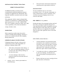
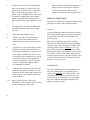
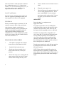
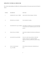
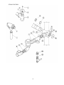
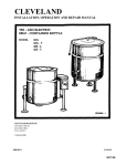
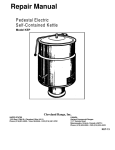
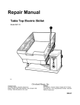
CLEVELAND
INSTALLATION, OPERATION AND REPAIR MANUAL
DIRECT STEAM KETTLES
MODEL
KDL - T
KDL
KDP
CLEVELAND RANGE INC.
1333 East 179th St.
Cleveland, Ohio U.S.A- 44110
(216)481-4900
9209 REV:1
233-01CC
KET-09
INSTALLATION. OPERATION -AND MAINTENANCE INSTRUCTIONS
FOR
DIRECT STEAM KETTLES
TILTING, STATIONARY, AND PEDESTAL MODELS
KDL-25-T
KDL-25
KDP-25
KDL-30-T
KDL-30
KDP-30
KDL-40-T
KDL-40
KDP-40
KDL-60-T
KDL-60
KDP-60
PRODUCT INFORMATION
MODEL STYLE ____________________
MODEL NO. _____________ SERIAL NO. ___________
INSTALLATION DATE______ INSTALLER ___________
RETAIN THIS MANUAL FOR YOUR REFERENCE
9203 REV:0
1
233-01TE
4.
INSTALLATION INSTRUCTIONS FOR
Fill out all carrier claims forms and have the
examining carrier sign and date each form.
DIRECT STEAM KETTLES
INSTALLATION
The first installation step is to refer to the
specification sheet for clearance requirements, in
order to determine the location of the kettle. Next,
carefully cut open the shipping carton for easy
removal of the kettle.
WARNING:Installauon of kettle must be
accomplished by qualified installation personnel,
working to all applicable local and national codes.
Improper installation of product could cause injury
or damage.
This equipment is built to comply with applicable
standards for manufacturers. Included among those
approval agencies are: UL, NSF, ASME/Ntl.Bd.,
CSA, ETL, and others. Many local codes exist, and it
is the responsibility of the owner and installer to
comply with these codes.
KDL SERIES (Tri-Leg Models)
Position the kettle in its permanent location, and level
the kettle by turning the adjustable flanged feet.
Once positioned and levelled, permanently secure the
kettle's flanged feet to the floor using 5/16" lag bolts
and floor anchors (to be supplied by the installer).
There are three bolts required to secure each of the
flanged feet.
INSPECTION
Before unpacking visually inspect the unit for
evidence of damage during shipping. If damage is
noticed, do not unpack the unit, follow shipping
damage instructions.
KDP SERIES (Pedestal Models)
SHIPPING DAMAGE INSTRUCTIONS
1.
Position the kettle in its permanent location,
and mark the floor around the circumference
of the base collar or the base plate. Locate the
centre of this circle and mark the floor at this
centre point. This is the point at which the
kettle's base plate will be secured to the floor.
2-
Lay kettle on its side (on a cushioned surface
to prevent scratching), and slide the base
collar up the pedestal, exposing the plate for
removal.
3.
Remove the four cap screws securing the base
plate and slide it off the kettle.
If shipping damage to the unit is discovered or
suspected, observe the following guidelines in
preparing a shipping damage claim.
1.
2.
3.
Write down a description of the damage or
the reason for suspecting damage as soon as
it is discovered. This will help in filling out
the claim forms later.
As soon as damage is discovered or
suspected, notify the carrier that delivered
the shipment.
Arrange for the carrier's representative to
examine damage.
2
4.
5.
Prepare the floor location, for mounting the
kettle, by installing a 3/4"(19mm) stud, cast
into the floor, at the base plate's centre point.
Note: a 3/4"(19mm) lag bolt and floor
anchor may be substituted for a cast-in stud.
The anchor is installed in the floor, and the
lag bolt is threaded down through the base
plate, into the anchor, after completion of step
6.
Thread the four 3/8"(10mm) levelling bolts
into plate from the top, and insert the plate
over stud.
6.
Adjust bolts until the plate is level.
7.
Install a nut on the 3/4" (19mm) bolt (or
insert a lag bolt if the alternate fastener
method is used) and secure base plate to the
floor.
8.
Check for level "set" of the kettle by placing
the kettle on the base plate with the screw
holes aligned and applying a carpenter's level
at the kettle rim. If the kettle is level, it may
be fastened in place with the four cap screws.
If the kettle is not level, the kettle must be
removed from the base, the plate loosened,
and the levelling bolts re-adjusted until a
level installation is attained.
9.
Slide the base collar down to the floor, and
draw a line around the circumference of the
pedestal at the top of the collar, using the top
of the collar as a guide. Slide the collar back
up the pedestal.
10.
Apply a bead of silicone sealer to the
circumference of the pedestal, at the line, and
also to the bottom rim of the collar.
3
Slide the collar down the pedestal and press it
tightly to the floor. The silicone sealer will
create a seal where the collar meets the
pedestal, and where the collar meets the floor.
SERVICE CONNECTIONS
Install service connections as required. Locations and
other data are shown on the specification sheet.
STEAM
All steam plumbing to and from the kettle and steam
boiler should be thoroughly cleaned and inspected for
din and debris before the final connections to the
kettle are made.
Refer to the specification sheet for the minimum
allowable size of the branch steam supply plumbing
(from the steam "main" plumbing or a nearby boiler).
Generally, kettles require a minimum of 3/4" i.p.s.
pipe. Kettles require 100 psi steam pressure. Check
the rating plate for the maximum steam pressure that
your kettle is rated for. If the steam supply pressure
exceeds the rated pressure, a pressure reducing valve
is required. The steam inlet is at the right side of the
kettle, as seen from the front.
CONDENSATE
The steam condensate trap must be plumbed to an
open, free-venting drain -or a condensate return
system, using minimum 1/2" NPT plumbing. The
condensate line is limited to a maximum rise of 10
feet in order for the steam pressure to adequately
force the condensate through the plumbing. Any
higher rise requires a pump.
If the steam boiler to which this kettle is installed
has a condensate return, a 1/2" (13mm) steam
strainer, a 1/2" (13mm) steam trap, and a 1/2" (13
mm) check valve must be installed on the
output (condensate) side of the kettle.
5.
Observe that the water in the kettle comes to
a boil.
6.
Close the steam supply valve.
7.
FAUCET (OPTIONAL)
The water faucet, with swing spout, requires 1/2
inch O.D. copper tube plumbing for hot/or cold
water supplies to the faucet (if so equipped).
ELECTRICAL
Power pour kettles require a permanent 115 volt
electrical connection. Refer to the specification
sheet for precise location. A kettle that is
connected to electricity must be grounded by the
installer, and installed in accordance with local
codes and/or the National Electrical Code
ANSI/NFPA No. 70-1990. Installation in Canada
must be in accordance with the Canadian Electric
Code CSA Standard C22.1.
FINAL INSTALLATION CHECK
1.
If the kettle is equipped with a tangent
draw-off valve, ensure that it is closed.
2.
Partially fill the kettle with water.
3.
Slowly turn the steam supply valve's
knob counter-clockwise, to the open
position.
4.
Release the safety valve, ensuring that the
steam escapes freely. Stay clear of steam
exhaust when releasing the safety valve.
4
Drain off the water by opening the draw-off
valve or tilting the kettle forward. Power
pour kettles ONLY: To raise the kettle,
press the top of the rocker switch. To lower
the kettle, press the bottom of the rocker
switch.
OPERATION
Ensure that there is an adequate steam
supply to the kettle.
For optimum performance on free-standing floor
model tilting kettles, open the drain petcock to drain
condensate from the kettle's jacket, then close the
drain petcock before applying steam to a cold kettle.
If the kettle is equipped with a tangent draw-off
valve, ensure that it is closed before filling the kettle.
To keep solid food particles out of the draw-off
valve, place either the solid or the perforated disc
(strainer) in the bottom of the kettle. Use the solid
disc if the liquid is to be retained, and the perforated
disc if the liquid is to be drained off.
Turn the steam control valve to the full open position
by turning the knob counter-clockwise, then allow
the kettle to preheat.
NOTE: When cooking egg and milk products, the
kettle should NOT be preheated, as products of this
nature adhere to hot cooking surfaces. These types of
foods should be placed in the kettle before heating is
begun.
Fill the kettle with product to the desired level.
CARE AND CLEANING
When the product has reached the desired
temperature, regulate the heat, as required, by
turning the steam control valve clockwise for less
steam, and therefore, a lower temperature.
Your kettle must be cleaned regularly to maintain its
fast, efficient cooking performance, and to ensure
its continued safe, reliable operation.
When cooking is complete, close the steam
control valve by turning the knob clockwise until
it stops turning.
WARNING: Do not use chlorine base
detergent.
1.
Prepare a warm water and mild detergent
solution in the kettle.
2.
Remove food soil inside the kettle using a
nylon brush. Do not use a metal bristle
brush, as this may permanently damage the
kettle's stainless steel surface.
Power-pour kettles are provided with a rockertype center-off switch for raising and lowering
the kettle. To raise the kettle, press the top of the
switch. To lower the kettle, press the bottom of
the switch- Release the switch, allowing it to
return to the center "off' position when the
desired degree of tilt has been reached. Limit
switches are provided that automatically stop the
tilt motion at the maximum limit of movement in
either direction.
3.
Loosen food which is stuck to the kettle by
allowing it to soak at a low temperature
(simmer or low boil).
4.
To raise and lower manual tilt, floor mounted
kettles, turn the handwheel counter-clockwise to
lower and clockwise to raise.
Open the draw-off valve or tilt kettle
forward to drain the wash water.
If the kettle is equipped with a draw-off valve, it
should be cleaned as follows:
For kettle/steamer combinations: If the boiler in a
steamer is supplying steam to a kettle, always
heat the kettle first. After the kettle contents are
heated, and the boiler's steam pressure returns to
normal, the steamer may be used- Pressure
steamer compartments should be sequentially
started, and preheated before cooking.
NOTE: As with cleaning food soil from any
cookware, an important part of kettle cleaning is
to prevent foods from drying on. For this reason,
cleaning should be completed immediately after
cooked foods are removed. Please refer to the
"Care and Cleaning" instructions for detailed
kettle washing procedures.
5
a.
Remove the drain strainer from the bottom of
the kettle. Thoroughly wash and rinse the
strainer, either in a sink or a dishwasher, then
replace it into the kettle.
b.
Disassemble the draw-off valve, first by
turning valve knob counter-clockwise, then
turning the large hex nut counter-clockwise,
until valve stem is free of the valve body.
c.
In a sink, wash and rinse the valve stem, hex
nut, and knob. Wash and rinse the inside of
the valve body using a nylon brush. Kettle
brushes and other accessories are available
from your authorized dealer.
d.
Reassemble the draw-off valve by reversing
the procedure for disassembly. THE
VALVE'S HEX NUT SHOULD BE
HAND TIGHT ONLY.
5.
Rinse the kettle interior thoroughly, then
drain rinse water.
6.
Leave the cover and draw-off valve open
when the kettle is not in use.
7.
Using mild soapy water and a damp
sponge, wash the exterior of the kettle,
rinse,and dry. Avoid soaking the electric
control panel. Always turn off equipment
power before using water to wash
equipment. DO NOT HOSE DOWN THE
KETTLE.
NOTE: For more difficult cleaning applications,
one of the following can be used: alcohol, baking
soda, vinegar, or a solution of ammonia in water.
Avoid the use of chloride cleansers, which may
damage the kettle's stainless steel surface.
WARNING: Steel wool should never be used for
cleaning the cooking chamber of the kettle.
Particles of the steel wool become embedded in
cooking surface and rust, and may corrode the
stainless steel.
MAINTENANCE
These kettles require very little preventive
maintenance, other than daily cleaning. Some
kettles are equipped with handwheel tilting
mechanisms, which require periodic preventive
maintenance to assure continued trouble-free
operation. Inspect the worm screw, tilting gears,
and bearings occasionally (at least once a year)
Lubricate as required using a high temperature
grease.
6
Each kettle is equipped with a steam trap in the line
from the kettle outlet to the drain, to remove the
condensate that forms inside the steam jacket. A
good steam trap at startup releases air and wet
steam into the drain line for a few minutes, then
holds the steam within the steam jacket. During
cooking, the trap periodically releases accumulated
condensate. If the kettle's cooking performance
becomes inadequate after long use, replacement of
the steam trap with a new one may restore kettle
operation to peak efficiency.
DRAW-OFF VALVE MAINTENANCE
To correct a leak at the draw-off valve, the source
of the leak must first be determined. Leaks from
around the valve stem are corrected by simply
replacing the "0" ring. Faulty seating of the valve
stem disc against the valve body may cause
dripping from the valve even when the valve is
tightly closed. This can often be corrected by
cleaning any residue from the disc and seat.
The Company supports a worldwide network of
Maintenance and Repair Centers, which are
regional distributors of parts and service. Contact
your nearest Maintenance and Repair Center for the
name of an authorized service agency in your area,
or for replacement parts, or information regarding
the proper maintenance and repair of your
equipment. In order to preserve the various agency
safety certifications (UL, A.G.A., CSA, CGA, NSF,
ASME/Ntl. Bd., etc.), only factory-supplied
replacement parts should be used. The use of other
than factory-supplied replacement parts will void
the warranty.
OPERATING CONTROLS & INDICATORS
For your better understanding and confidence, the following explanation of the control system used on this kettle is
offered.
ITEM NO.
DESCRIPTION
FUNCTION
4
Steam Inlet Valve ( Pg. 233-09DR )
Opens and closes the steam supply to the kettle.
15
Hand wheel ( Pg. 233-09DR )
Turn to tilt kettle for pouring.
13
Pressur Relief Valve ( Pg. 233-08DR ) In the unlikely event that there is an excess steam build-up
in the jacket, this valve automatically opens to relieve this
pressure.
16
Drain Cock ( Pg. 233-08DR )
Used to drain condensate from the bottom of tilting units
only.
1-7
Draw-Off Valve ( Pg. 600-04TD )
This valve is used to empty the kettle of either food
product or wash water. It is supplied as standard
equipment on stationary models and is optional on tilting
kettles.
20
Power Tilt Control Switch
This switch allows the operator to tilt the kettle up or
( Pg. 233-10DR )
down.
7
PARTS LIST - STEAM CONTROL
ITEM NO.
PART NO.
DESCRIPTION
QTY.
1.
2.
3.
KE51892
KE51888
FA11501
Retaining ring
Washer
Valve knob screw
1
1
1
4.
SE00028
Valve knob assembly (includes item 1,2,3)
1
5.
6.
KE51259
KE51720
3/4" Chrome steam inlet valve
3/4" Pressure relief valve 50 psi
1
1
7.
KE50221
Blow down tube
1
8.
9.
KE52700
FA00596
1/2" Check valve
Nipple 1/2" NPT x 1 1/2" long
1
2
10.
11.
12.
* 14.
* 15.
* 16.
FI05078
KE52701
KE52702
FA00113
KE50676
KE00353
KE00352
KE51886
KE51711
KE50666
KE00349
FA95007
FA00218
FI00352
KE50675
90° Elbow (chrome plated)
1/2" Steam trap
1/2" Strainer
"O" Ring
Connector
Trunnion bearing, spring assist cover
Trunnion bearing, spring assist cover
Grease nipple
Bearing
Spherical washer
Screw 5/16"-18
Retaining ring
"O" Ring
Reducer bushing 1/2 x 3/8
Drain cock
2
1
1
1
1
1
* 17.
* 18.
* 19.
* 20.
* 21.
* 22.
* 23.
* 24.
*
Applicable to tilting models only
8
2
2
1
1
1
2
1
1
STEAM CONTROL
9
PARTS LIST - CONTROL HOUSING
ITEM NO.
PART NO.
DESCRIPTION
QTY.
1.
FA11134
Screw #10-24
2
2.
FA11501
Valve knob screw
1
3.
SE00028
Valve knob (Item no. 2 included)
1
4.
KE00350
3/4" Brass steam inlet valve
1
(Item no. 2 & 3 not included)
5.
FA95008
Lock nut 3/4-16
2
6.
FA30088
Tilt shaft washer
1
7.
SE00036
Thrust bearing assembly
2
(Item no. 27, 28, & 29 included)
8.
FA95007
Trunnion retaining ring
1
9.
FA00218
Trunnion "O" ring
2
10.
FA95012
Worm gear key
1
11.
KE51711
Trunnion bearing
1
12.
FA95005
Tension pin
1
13.
KE50375
Tilt shaft
1
14.
FA19501
Hand wheel allen screw
1
15.
KE53726
Hand wheel
1
16.
KE00164
Steam inlet bearing housing
1
17.
KE00151
Worm gear
1
18.
FA19186
Worm gear allen screw
1
19.
KE50315
Worm
1
20.
KE50324
Console cover
1
21.
KE51731
Bearing, tilt shaft
1
22.
KE51891
Washer, 1 1/2" O.D. x 13/16" I.D. x .037" W.
23.
SE00034
Bearing assembly
24.
FA20029
Nut, hex, 5/16-24
25.
FA10623
Bolt, 5/16-24 x 1 1/2"
Not available
26.
27.
KE52192
Washer, thrust bearing
2
28.
KE52191
Bearing, thrust
1
29.
KE52193
Spacer, thrust bearing
1
10
CONTROL HOUSING
11
PARTS LIST - POWER TILT CONTROL HOUSING (OPTIONAL)
ITEM NO.
1.
2
3.
4.
5.
6.
7.
8.
9.
10.
11.
12.
13.
14.
15.
16.
17.
18.
19.
20.
21.
22.
23.
24.
25.
26.
27.
28.
29.
30.
31.
32.
33.
34.
35.
36.
37.
38.
39.
40.
41.
42.
PART NO.
KE51012
FA11134
KE50577
KE52832
KE50583
KE50582
KE00350
FA11501
SE00028
KE50441
FA95008
KE50581
FA30088
SE00036
FA95005
KE50315
FA19186
KE00150
KE51011
KE51009
KE51010
KE51007
FA00012
KE50579
KE50580
KE51731
FA95012
FA00218
FA95007
FA11081
KE51223
KE50376
SK50054
KE50377
SK50055
KE00164
KE51711
SE00034
FA10623
FA20229
KE51891
KE52192
KE52191
KE52193
FA95037
DESCRIPTION
Gear box lid
Screw, 10-24 x 3/8" S.S.
Motor, 1/15 h.p., 25-40 gallon
Motor, 1/8 h.p., 60 gallon & up
Buna-N insert
Coupling
3/4" Brass steam inlet valve
Screw
Steam inlet knob ass'y. (Item no. 7 included)
Tilt shaft
Locknut, 3/4-16
Bridge rectifier
Washer, 1 1/2" O.D. x 13/16" I.D. x .125 W.
Bearing assembly
Tension pin
Worm
Allen screw, worm gear
Worm gear
Contact section
Square spacer plate
Square actuator
Micro switch
"0" ring, circuit breaker
Circuit breaker, 1 Amp
Water resistant boot
Bearing, tilt shaft
Worm gear key
"0" ring
Retaining ring
Screw, 8-32 x 1/2" S.S.
Bottom cover
Terminal block end section (Large, white)
Terminal block end section (Small, black)
Terminal block end section (Large, white)
Terminal block end section (Small, black)
Trunnion bearing housing
Roller bearing, trunnion
Bearing assembly
Bolt, 5/16-24 x 1 1/2"
Nut, hex, 5/16-24
Washer, 1 1/2" O.D. x 13/16" I.D. x .037" W.
Washer, thrust bearing
Bearing, thrust
Spacer, thrust bearing
Key, 3/16"x 3/16"x 3/4"
12
QTY.
1
1
1
1
2
1
1
1
2
1
1
2
1
1
1
1
6
1
1
2
1
1
1
1
1
4
1
4
1
1
1
3
3
1
2
1
1
1
2
4
2
2
1
POWER TILT CONTROL HOUSING (OPTIONAL)
13
PARTS LIST - 2" TANGENT DRAW-OFF VALVE
ITEM NO.
1. to 7.
1.
2.
3.
4.
5.
6.
7.
PART NO.
KE50972-B
FA21008
FA95049
KE527551
KE52754
KE52753
KE52752
FA00111
KE52751
DESCRIPTION
Draw-off assembly
Hex nut
Wing nut
Knob
Hex nut
Retainer
Piston
"O" Ring
Valve body
QTY.
1
1
1
1
1
1
1
1
14
PARTS LIST - HINGE ASSEMBLY
ITEM NO. PART NO.
1.-9.
SE00057
SE00058
1.
KE51218
2.
KE50824
3.
KE50823
4.
KE50820
5.
KE50819
6.
FA11507
7.
FA11284
8.
KE50122
KE50121
9.
KE50821
10.
KE53478
11.
12.
KE00095
13.
FA30500
14.
FA11223
DESCRIPTION
Hinge assembly (40 gal. and under)
Hinge assembly (60 gal. and over)
Body, spring assist hinge
Hinge bearing
Pin (hinge)
Insert, brass adjustment
End piece
Screws, adjustment
Bolts, end block
Spring (40 gal. and under)
Spring (60 gal. and over)
Cylinder
Knob, ball type
Cover handle (specify model)
Lid holder
Washer, lid holder
Bolt, lid holder
15
QTY.
1
1
1
1
1
1
1
2
2
1
1
1
1
1
1
1
1
PARTS LIST - FAUCET
ITEM NO.
1
2
3
4
5
6
7
8
PART NO.
KE50833
KE50828
KE50829
KE51404
KE51736
FA95022
FA00016
SE50021
SE50020
KE51403
SE50022
DESCRIPTION
3/4" Spout
for KS S-LA
for KS20SA, KS30SA KS40SA
for KS60SA
Spout nut, short (used on spout KE50833)
Spout nut, tall (used on spouts
KE50828 & KE50829)
Retaining ring
"O"ring
Cold water stem assemby
Hot water stem assembly
Double pantry control valve
(c/w item no. 5,6,8)
Yoke connection kit
16
QTY.
1
1
1
1
1
1
1
1
1
ALL KETTLES AND SKILLETS HINGE ADJUSTMENT
INSTRUCTIONS
1.
Insert 3/8" Allen wrench.
2.
Turn clockwise to relieve tension on spring.
3.
While tension is released remove one of the two slotted screws.
4.
To prevent Allen wrench from springing back abruptly while the second slotted screw is removed,
insert a pin (approximately 1/8") in the hole where the first slotted screw was removed from.
5.
Remove second slotted screw.
6.
While holding Allen wrench remove pin.
7.
Turn Allen wrench clockwise to tighten or counter-clockwise to loosen tension to produce desired
effect
8.
Re-insert pin in one of the two holes.
9.
Tighten one slotted screw in the other hole (it may be necessary to turn Allen wrench slightly to
align holes.)
10. Remove pin and repeat step number 9 for other slotted screw.
17
SERVICING GUIDE
This section contains information intended for use by Authorized Service Personnel only.
A/ PROBLEM : Kettle heats too slowly or does not come to a boil.
B/
Probable Cause
Remedy
1. Inadequate steam flow.
Check for correct steam using chart below. If
kettle is connected to a steamer and powered by a
generator the units should be operated sequentially
(kettle boiling first, then start steamer).
2. Steam trap not operating properly.
The trap should open periodically to dump,
condensate, then dose- If it does not open or close
it should be cleaned or replaced.
3. Food batches are not always the same.
When checking make certain that the original state
(ie. fresh or frozen) and quantity of food product
is the same.
PROBLEM : The trunnion housing leaks steam.
C/
Probable Cause
Remedy
1. Trunnion "O" rings are worn.
Replace "O" rings.
PROBLEM : Steam trap makes a "banging" noise when steam applied to cold kettle.
Probable Cause
Remedy
1. Kettle condensate has not been drained.
On all tilting trileg and pedestal kettles the condensate
should be drained from the cold kettle. This is done
before steam is applied using the drain petcock valve on
the bottom of the kettle.
STEAM FLOW RATING OF
STEAM GENERATORS
GAS INPUT
BTU/HOUR
100,000
160,000
200,000
250,000
300,000
STEAM OUTPUT
LBS./HOUR
60
95
125
150
180
BOILER
H.P.
1.7
2.8
3.6
4.4
5-2
ELECTRIC
KW INPUT
18 KW
24 KW
27 KW
36 KW
48 KW
60
70
90
120
150
1.7
2.0
2.6
3.5
43
18
STEAM FLOW RATE
REQUIREMENTS FOR KETTLES
Capacity
Fast
Medium Speed
Stock
Gal/Lit.
Cooking
Cooking
Kettle
5/17
11
9
6
10/42
22
18
11
25/95
55
44
28
40/151
88
70
44
60/227
132
105
66
Note: Above shows Ibs. per hour with 10-15 psig steam
at the kettle. The use of higher steam pressures
(20-25 psig) will reduce heat-up time 5 to 20 % .