1
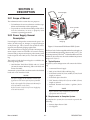
Automated Plasma
Cutting Power Supply
PAK Master® 150XL™
TM
TM
A-02861
Service Manual
November 18, 2005
Manual No. 0-2825
WARNINGS
Read and understand this entire Manual and your employer’s safety practices before installing,
operating, or servicing the equipment.
While the information contained in this Manual represents the Manufacturer's best judgement, the
Manufacturer assumes no liability for its use.
Automated Plasma Cutting Power Supply
Pak Master® 150XL
Service Manual Number 0-2825
Published by:
Thermal Dynamics Corporation
82 Benning Street
West Lebanon, New Hampshire, USA 03784
(603) 298-5711
www.thermal-dynamics.com
©Copyright 2000 by
Thermal Dynamics Corporation
All rights reserved.
Reproduction of this work, in whole or in part, without written permission of the publisher is prohibited.
The publisher does not assume and hereby disclaims any liability to
any party for any loss or damage caused by any error or omission in
this Manual, whether such error results from negligence, accident, or
any other cause.
Printed in the United States of America
Publication Date: November 18, 2005
Record the following information for Warranty purposes:
Where Purchased:____________________________________
Purchase Date:_______________________________________
Power Supply Serial #:________________________________
Torch Serial #:_______________________________________
TABLE OF CONTENTS
SECTION 1:
GENERAL INFORMATION ................................................................................................. 1-1
1.01
1.02
1.03
1.04
1.05
1.06
1.07
1.08
Notes, Cautions and Warnings .....................................................................
Important Safety Precautions ........................................................................
Publications ..................................................................................................
Note, Attention et Avertissement ...................................................................
Precautions De Securite Importantes ............................................................
Documents De Reference .............................................................................
Declaration of Conformity ..............................................................................
Statement of Warranty ..................................................................................
1-1
1-1
1-2
1-3
1-3
1-5
1-7
1-8
SECTION 2:
INTRODUCTION ................................................................................................................... 1
2.01 Scope Of Manual ............................................................................................. 1
2.02 General Service Philosophy ............................................................................. 1
2.03 Service Responsibilities ................................................................................... 1
SECTION 3:
DESCRIPTION ................................................................................................................... 3-1
3.01
3.02
3.03
3.04
2.05
Scope of Manual ...........................................................................................
Power Supply General Description ................................................................
Specifications/Design Features .....................................................................
Power Supply Options and Accessories .......................................................
Theory Of Operation ......................................................................................
3-1
3-1
3-2
3-3
3-3
SECTION 4:
SERVICE .......................................................................................................................... 4-1
4.01
4.02
4.03
4.04
4.05
4.06
4.07
4.08
4.09
4.10
Introduction ................................................................................................... 4-1
Periodic Inspection & Procedures ................................................................. 4-1
System Theory ............................................................................................. 4-3
Common Operating Problems ....................................................................... 4-5
Troubleshooting Guide - General Information ................................................. 4-6
Circuit Fault Isolation .................................................................................... 4-7
Main Input and Internal Power Problems ....................................................... 4-8
Pilot Arc Problems ....................................................................................... 4-10
Main Cutting Arc Problems .......................................................................... 4-12
Test Procedures ........................................................................................... 4-13
SECTION 5:
REPLACEMENT PROCEDURES ...................................................................................... 5-1
5.01
5.02
5.03
5.04
5.05
5.06
5.07
5.08
5.09
Introduction ................................................................................................... 5-1
Anti-Static Handling Procedures ................................................................... 5-1
Parts Replacement - General Information ...................................................... 5-1
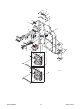
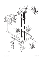
Major External Parts Replacement ............................................................... 5-2
Access Panel Parts Replacement ................................................................ 5-3
Left Side Center Chassis Parts Replacement ............................................... 5-4
Right Side Center Chassis Parts Replacement ............................................. 5-8
Base Parts Replacement ............................................................................. 5-13
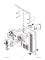
Rear Panel Parts Replacement .................................................................... 5-16
TABLE OF CONTENTS (Continued)
SECTION 6:
PARTS LISTS .................................................................................................................... 6-1
6.01 Introduction ................................................................................................... 6-1
6.02 Ordering Information ...................................................................................... 6-1
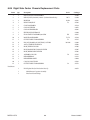
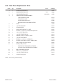
6.03 Major External Replacement Parts ............................................................... 6-2
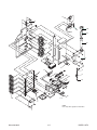
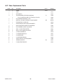
6.04 Access Panel Replacement Parts ................................................................ 6-3
6.05 Left Side Center Chassis Replacement Parts ............................................... 6-4
6.06 Right Side Center Chassis Replacement Parts ............................................ 6-6
6.07 Base Replacement Parts ............................................................................. 6-8
6.08 Rear Panel Replacement Parts ................................................................... 6-10
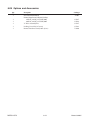
6.09 Options and Accessories ............................................................................ 6-12
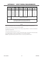
APPENDIX 1: INPUT WIRING REQUIREMENTS ....................................................................... A-1
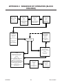
APPENDIX 2: SEQUENCE OF OPERATION (BLOCK DIAGRAM) ............................................ A-2
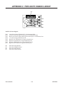
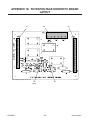
APPENDIX 3: POT/LED PC BOARD LAYOUT .......................................................................... A-3
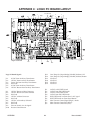
APPENDIX 4: LOGIC PC BOARD LAYOUT ............................................................................... A-4
APPENDIX 5: GATE DRIVE PC BOARD LAYOUT ..................................................................... A-6
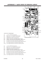
APPENDIX 6: PILOT/OUTPUT PC BOARD LAYOUT AND WIRING CONNECTION DIAGRAM .. A-8
APPENDIX 7: CD PC BOARD LAYOUT .................................................................................. A-10
APPENDIX 8: INPUT PC BOARD LAYOUT ............................................................................. A-11
APPENDIX 9: FET PC BOARD LAYOUT ................................................................................. A-12
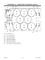
APPENDIX 10: CAPACITOR PC BOARD LAYOUT .................................................................. A-14
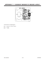
APPENDIX 11: CURRENT SENSOR PC BOARD LAYOUT ..................................................... A-15
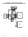
APPENDIX 12: 36VAC CIRCUIT DIAGRAM ............................................................................. A-16
APPENDIX 13: RECOMMENDED ROUTINE MAINTENANCE SCHEDULE
FOR LIQUID COOLED PLASMA CUTTING SYSTEMS .................................................... A-17
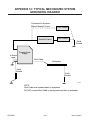
APPENDIX 14: TYPICAL MECHANIZED SYSTEM GROUNDING DIAGRAM ........................... A-18
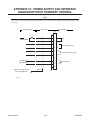
APPENDIX 15: POWER SUPPLY CNC INTERFACE DIAGRAM
WITHOUT STANDOFF CONTROL ................................................................................... A-19
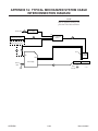
APPENDIX 16: TYPICAL MECHANIZED SYSTEM CABLE INTERCONNECTION DIAGRAM ... A-20
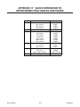
APPENDIX 17: QUICK REFERENCE TO INTERCONNECTING CABLES AND HOSES .......... A-21
TABLE OF CONTENTS (Continued)
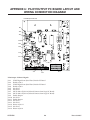
APPENDIX 18: FILTER/VOLTAGE DIVIDER PC BOARD LAYOUT .......................................... A-22
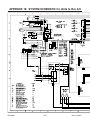
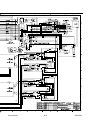
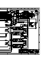
APPENDIX 19: SYSTEM SCHEMATIC for Units to Rev AH ..................................................... A-24
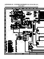
APPENDIX 20: SYSTEM SCHEMATIC for Units Rev AJ and Later ........................................... A-26
SECTION 1:
GENERAL INFORMATION
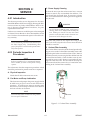
GASES AND FUMES
Gases and fumes produced during the plasma cutting
process can be dangerous and hazardous to your health.
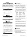
1.01 Notes, Cautions and Warnings
• Keep all fumes and gases from the breathing area.
Keep your head out of the welding fume plume.
Throughout this manual, notes, cautions, and warnings
are used to highlight important information. These highlights are categorized as follows:
• Use an air-supplied respirator if ventilation is not
adequate to remove all fumes and gases.
NOTE
• The kinds of fumes and gases from the plasma arc
depend on the kind of metal being used, coatings
on the metal, and the different processes. You must
be very careful when cutting or welding any metals which may contain one or more of the following:
An operation, procedure, or background information which requires additional emphasis or is helpful in efficient operation of the system.
CAUTION
Antimony
Arsenic
Barium
Beryllium
Cadmium
A procedure which, if not properly followed, may
cause damage to the equipment.
Chromium
Cobalt
Copper
Lead
Manganese
Mercury
Nickel
Selenium
Silver
Vanadium
• Always read the Material Safety Data Sheets
(MSDS) that should be supplied with the material
you are using. These MSDSs will give you the information regarding the kind and amount of fumes
and gases that may be dangerous to your health.
WARNING
A procedure which, if not properly followed, may
cause injury to the operator or others in the operating area.
• For information on how to test for fumes and gases
in your workplace, refer to item 1 in Subsection 1.03,
Publications in this manual.
1.02 Important Safety Precautions
• Use special equipment, such as water or down draft
cutting tables, to capture fumes and gases.
WARNINGS
• Do not use the plasma torch in an area where combustible or explosive gases or materials are located.
• Phosgene, a toxic gas, is generated from the vapors
of chlorinated solvents and cleansers. Remove all
sources of these vapors.
OPERATION AND MAINTENANCE OF
PLASMA ARC EQUIPMENT CAN BE DANGEROUS AND HAZARDOUS TO YOUR
HEALTH.
• This product, when used for welding or cutting,
produces fumes or gases which contain chemicals
known to the State of California to cause birth defects and, in some cases, cancer. (California Health
& Safety Code Sec. 25249.5 et seq.)
Plasma arc cutting produces intense electric and
magnetic emissions that may interfere with the
proper function of cardiac pacemakers, hearing
aids, or other electronic health equipment. Persons who work near plasma arc cutting applications should consult their medical health professional and the manufacturer of the health
equipment to determine whether a hazard exists.
ELECTRIC SHOCK
Electric Shock can injure or kill. The plasma arc process
uses and produces high voltage electrical energy. This
electric energy can cause severe or fatal shock to the operator or others in the workplace.
To prevent possible injury, read, understand and
follow all warnings, safety precautions and instructions before using the equipment. Call 1-603298-5711 or your local distributor if you have any
questions.
Date: November 15, 2004
• Never touch any parts that are electrically “live”
or “hot.”
1-1
GENERAL INFORMATION
• Wear dry gloves and clothing. Insulate yourself
from the work piece or other parts of the welding
circuit.
PLASMA ARC RAYS
• Repair or replace all worn or damaged parts.
Plasma Arc Rays can injure your eyes and burn your skin.
The plasma arc process produces very bright ultra violet
and infra red light. These arc rays will damage your
eyes and burn your skin if you are not properly protected.
• Extra care must be taken when the workplace is
moist or damp.
• Install and maintain equipment according to NEC
code, refer to item 9 in Subsection 1.03, Publications.
• To protect your eyes, always wear a welding helmet or shield. Also always wear safety glasses with
side shields, goggles or other protective eye wear.
• Disconnect power source before performing any
service or repairs.
• Wear welding gloves and suitable clothing to protect your skin from the arc rays and sparks.
• Read and follow all the instructions in the Operating Manual.
• Keep helmet and safety glasses in good condition.
Replace lenses when cracked, chipped or dirty.
FIRE AND EXPLOSION
• Protect others in the work area from the arc rays.
Use protective booths, screens or shields.
Fire and explosion can be caused by hot slag, sparks, or
the plasma arc.
• Use the shade of lens as suggested in the following
per ANSI/ASC Z49.1:
• Be sure there is no combustible or flammable material in the workplace. Any material that cannot
be removed must be protected.
• Ventilate all flammable or explosive vapors from
the workplace.
• Do not cut or weld on containers that may have
held combustibles.
Minimum Protective
Shade No.
Suggested
Shade No.
Less Than 300*
8
9
300 - 400*
9
12
400 - 800*
10
14
* These values apply where the actual arc is clearly
seen. Experience has shown that lighter filters
may be used when the arc is hidden by the workpiece.
• Provide a fire watch when working in an area where
fire hazards may exist.
• Hydrogen gas may be formed and trapped under
aluminum workpieces when they are cut underwater or while using a water table. DO NOT cut
aluminum alloys underwater or on a water table
unless the hydrogen gas can be eliminated or dissipated. Trapped hydrogen gas that is ignited will
cause an explosion.
1.03 Publications
Refer to the following standards or their latest revisions
for more information:
1. OSHA, SAFETY AND HEALTH STANDARDS, 29CFR
1910, obtainable from the Superintendent of Documents, U.S. Government Printing Office, Washington,
D.C. 20402
NOISE
2. ANSI Standard Z49.1, SAFETY IN WELDING AND
CUTTING, obtainable from the American Welding Society, 550 N.W. LeJeune Rd, Miami, FL 33126
Noise can cause permanent hearing loss. Plasma arc processes can cause noise levels to exceed safe limits. You
must protect your ears from loud noise to prevent permanent loss of hearing.
3. NIOSH, SAFETY AND HEALTH IN ARC WELDING
AND GAS WELDING AND CUTTING, obtainable
from the Superintendent of Documents, U.S. Government Printing Office, Washington, D.C. 20402
• To protect your hearing from loud noise, wear protective ear plugs and/or ear muffs. Protect others
in the workplace.
4. ANSI Standard Z87.1, SAFE PRACTICES FOR OCCUPATION AND EDUCATIONAL EYE AND FACE PROTECTION, obtainable from American National Standards Institute, 1430 Broadway, New York, NY 10018
• Noise levels should be measured to be sure the decibels (sound) do not exceed safe levels.
• For information on how to test for noise, see item 1
in Subsection 1.03, Publications, in this manual.
GENERAL INFORMATION
Arc Current
5. ANSI Standard Z41.1, STANDARD FOR MEN’S
SAFETY-TOE FOOTWEAR, obtainable from the American National Standards Institute, 1430 Broadway, New
York, NY 10018
1-2
Date: November 15, 2004
6. ANSI Standard Z49.2, FIRE PREVENTION IN THE USE OF
CUTTING AND WELDING PROCESSES, obtainable from
American National Standards Institute, 1430 Broadway, New
York, NY 10018
NOTE
Toute opération, procédure ou renseignement
général sur lequel il importe d’insister davantage
ou qui contribue à l’efficacité de fonctionnement
du système.
7. AWS Standard A6.0, WELDING AND CUTTING CONTAINERS WHICH HAVE HELD COMBUSTIBLES, obtainable from American Welding Society, 550 N.W.
LeJeune Rd, Miami, FL 33126
ATTENTION
8. NFPA Standard 51, OXYGEN-FUEL GAS SYSTEMS
FOR WELDING, CUTTING AND ALLIED PROCESSES, obtainable from the National Fire Protection
Association, Batterymarch Park, Quincy, MA 02269
Toute procédure pouvant résulter
l’endommagement du matériel en cas de nonrespect de la procédure en question.
9. NFPA Standard 70, NATIONAL ELECTRICAL CODE,
obtainable from the National Fire Protection Association, Batterymarch Park, Quincy, MA 02269
AVERTISSEMENT
10. NFPA Standard 51B, CUTTING AND WELDING PROCESSES, obtainable from the National Fire Protection
Association, Batterymarch Park, Quincy, MA 02269
11. CGA Pamphlet P-1, SAFE HANDLING OF COMPRESSED GASES IN CYLINDERS, obtainable from the
Compressed Gas Association, 1235 Jefferson Davis
Highway, Suite 501, Arlington, VA 22202
12. CSA Standard W117.2, CODE FOR SAFETY IN WELDING AND CUTTING, obtainable from the Canadian
Standards Association, Standards Sales, 178 Rexdale
Boulevard, Rexdale, Ontario, Canada M9W 1R3
Toute procédure pouvant provoquer des blessures
de l’opérateur ou des autres personnes se trouvant
dans la zone de travail en cas de non-respect de la
procédure en question.
1.05 Precautions De Securite
Importantes
AVERTISSEMENTS
13. NWSA booklet, WELDING SAFETY BIBLIOGRAPHY
obtainable from the National Welding Supply Association, 1900 Arch Street, Philadelphia, PA 19103
L’OPÉRATION ET LA MAINTENANCE DU
MATÉRIEL DE SOUDAGE À L’ARC AU JET
DE PLASMA PEUVENT PRÉSENTER DES
RISQUES ET DES DANGERS DE SANTÉ.
14. American Welding Society Standard AWSF4.1, RECOMMENDED SAFE PRACTICES FOR THE PREPARATION FOR WELDING AND CUTTING OF CONTAINERS AND PIPING THAT HAVE HELD HAZARDOUS
SUBSTANCES, obtainable from the American Welding
Society, 550 N.W. LeJeune Rd, Miami, FL 33126
Coupant à l’arc au jet de plasma produit de l’énergie
électrique haute tension et des émissions
magnétique qui peuvent interférer la fonction
propre d’un “pacemaker” cardiaque, les appareils
auditif, ou autre matériel de santé electronique.
Ceux qui travail près d’une application à l’arc au
jet de plasma devrait consulter leur membre
professionel de médication et le manufacturier de
matériel de santé pour déterminer s’il existe des
risques de santé.
15. ANSI Standard Z88.2, PRACTICE FOR RESPIRATORY
PROTECTION, obtainable from American National
Standards Institute, 1430 Broadway, New York, NY
10018
1.04 Note, Attention et
Avertissement
Il faut communiquer aux opérateurs et au personnel TOUS les dangers possibles. Afin d’éviter les
blessures possibles, lisez, comprenez et suivez tous
les avertissements, toutes les précautions de sécurité
et toutes les consignes avant d’utiliser le matériel.
Composez le + 603-298-5711 ou votre
distributeur local si vous avez des questions.
Dans ce manuel, les mots “note,” “attention,” et “avertissement”
sont utilisés pour mettre en relief des informations à caractère
important. Ces mises en relief sont classifiées comme suit :
Date: November 15, 2004
1-3
GENERAL INFORMATION
FUMÉE et GAZ
CHOCELECTRIQUE
La fumée et les gaz produits par le procédé de jet de plasma
peuvent présenter des risques et des dangers de santé.
• Eloignez toute fumée et gaz de votre zone de respiration.
Gardez votre tête hors de la plume de fumée provenant du
chalumeau.
• Utilisez un appareil respiratoire à alimentation en air si
l’aération fournie ne permet pas d’éliminer la fumée et les
gaz.
• Les sortes de gaz et de fumée provenant de l’arc de plasma
dépendent du genre de métal utilisé, des revêtements se
trouvant sur le métal et des différents procédés. Vous devez
prendre soin lorsque vous coupez ou soudez tout métal
pouvant contenir un ou plusieurs des éléments suivants:
antimoine
argent
arsenic
baryum
béryllium
cadmiummercure
chrome
cobalt
cuivre
manganèse
nickel
plomb
sélénium
vanadium
• Lisez toujours les fiches de données sur la sécurité
des matières (sigle américain “MSDS”); celles-ci
devraient être fournies avec le matériel que vous
utilisez. Les MSDS contiennent des renseignements
quant à la quantité et la nature de la fumée et des gaz
pouvant poser des dangers de santé.
• Pour des informations sur la manière de tester la
fumée et les gaz de votre lieu de travail, consultez
l’article 1 et les documents cités à la page 5.
• Utilisez un équipement spécial tel que des tables de
coupe à débit d’eau ou à courant descendant pour
capter la fumée et les gaz.
• N’utilisez pas le chalumeau au jet de plasma dans une
zone où se trouvent des matières ou des gaz combustibles ou explosifs.
• Le phosgène, un gaz toxique, est généré par la fumée
provenant des solvants et des produits de nettoyage
chlorés. Eliminez toute source de telle fumée.
• Ce produit, dans le procéder de soudage et de coupe,
produit de la fumée ou des gaz pouvant contenir des
éléments reconnu dans L’état de la Californie, qui
peuvent causer des défauts de naissance et le cancer. (La
sécurité de santé en Californie et la code sécurité Sec. 25249.5
et seq.)
GENERAL INFORMATION
Les chocs électriques peuvent blesser ou même tuer. Le procédé
au jet de plasma requiert et produit de l’énergie électrique haute
tension. Cette énergie électrique peut produire des chocs graves,
voire mortels, pour l’opérateur et les autres personnes sur le
lieu de travail.
• Ne touchez jamais une pièce “sous tension” ou “vive”;
portez des gants et des vêtements secs. Isolez-vous
de la pièce de travail ou des autres parties du circuit
de soudage.
• Réparez ou remplacez toute pièce usée ou
endommagée.
• Prenez des soins particuliers lorsque la zone de travail est humide ou moite.
• Montez et maintenez le matériel conformément au
Code électrique national des Etats-Unis. (Voir la page
5, article 9.)
• Débranchez l’alimentation électrique avant tout travail d’entretien ou de réparation.
• Lisez et respectez toutes les consignes du Manuel de
consignes.
INCENDIE ET EXPLOSION
Les incendies et les explosions peuvent résulter des scories
chaudes, des étincelles ou de l’arc de plasma. Le procédé
à l’arc de plasma produit du métal, des étincelles, des
scories chaudes pouvant mettre le feu aux matières combustibles ou provoquer l’explosion de fumées
inflammables.
• Soyez certain qu’aucune matière combustible ou inflammable ne se trouve sur le lieu de travail. Protégez
toute telle matière qu’il est impossible de retirer de la
zone de travail.
• Procurez une bonne aération de toutes les fumées
inflammables ou explosives.
• Ne coupez pas et ne soudez pas les conteneurs ayant
pu renfermer des matières combustibles.
• Prévoyez une veille d’incendie lors de tout travail dans
une zone présentant des dangers d’incendie.
• Le gas hydrogène peut se former ou s’accumuler sous
les pièces de travail en aluminium lorsqu’elles sont
coupées sous l’eau ou sur une table d’eau. NE PAS
couper les alliages en aluminium sous l’eau ou sur une table
d’eau à moins que le gas hydrogène peut s’échapper ou se
dissiper. Le gas hydrogène accumulé explosera si enflammé.
1-4
Date: November 15, 2004
1.06 Documents De Reference
RAYONS D’ARC DE PLASMA
Les rayons provenant de l’arc de plasma peuvent blesser vos
yeux et brûler votre peau. Le procédé à l’arc de plasma produit
une lumière infra-rouge et des rayons ultra-violets très forts.
Ces rayons d’arc nuiront à vos yeux et brûleront votre peau si
vous ne vous protégez pas correctement.
• Pour protéger vos yeux, portez toujours un casque ou un
écran de soudeur. Portez toujours des lunettes de sécurité
munies de parois latérales ou des lunettes de protection ou
une autre sorte de protection oculaire.
• Portez des gants de soudeur et un vêtement protecteur
approprié pour protéger votre peau contre les
étincelles et les rayons de l’arc.
• Maintenez votre casque et vos lunettes de protection
en bon état. Remplacez toute lentille sale ou
comportant fissure ou rognure.
• Protégez les autres personnes se trouvant sur la zone
de travail contre les rayons de l’arc en fournissant des
cabines ou des écrans de protection.
• Utilisez la nuance de lentille qui est suggèrée dans le
recommendation qui suivent ANSI/ASC Z49.1:
Courant Arc
Nuance Minimum
Protective Numéro
Nuance Suggerée
Numéro
Moins de 300*
8
9
300 - 400*
9
12
400 - 800*
10
14
* Ces valeurs s’appliquent ou l’arc actuel est observé
clairement. L’experience a démontrer que les filtres
moins foncés peuvent être utilisés quand l’arc est
caché par moiceau de travail.
BRUIT
Le bruit peut provoquer une perte permanente de l’ouïe.
Les procédés de soudage à l’arc de plasma peuvent
provoquer des niveaux sonores supérieurs aux limites
normalement acceptables. Vous dú4ez vous protéger les
oreilles contre les bruits forts afin d’éviter une perte
permanente de l’ouïe.
• Pour protéger votre ouïe contre les bruits forts, portez
des tampons protecteurs et/ou des protections
auriculaires. Protégez également les autres personnes
se trouvant sur le lieu de travail.
• Il faut mesurer les niveaux sonores afin d’assurer que les
décibels (le bruit) ne dépassent pas les niveaux sûrs.
• Pour des renseignements sur la manière de tester le bruit,
consultez l’article 1, page 5.
Date: November 15, 2004
Consultez les normes suivantes ou les révisions les plus
récentes ayant été faites à celles-ci pour de plus amples
renseignements :
1. OSHA, NORMES DE SÉCURITÉ DU TRAVAIL ET DE
PROTECTION DE LA SANTÉ, 29CFR 1910,
disponible auprès du Superintendent of Documents,
U.S. Government Printing Office, Washington, D.C.
20402
2. Norme ANSI Z49.1, LA SÉCURITÉ DES
OPÉRATIONS DE COUPE ET DE SOUDAGE,
disponible auprès de la Société Américaine de
Soudage (American Welding Society), 550 N.W.
LeJeune Rd., Miami, FL 33126
3. NIOSH, LA SÉCURITÉ ET LA SANTÉ LORS DES
OPÉRATIONS DE COUPE ET DE SOUDAGE À
L’ARC ET AU GAZ, disponible auprès du Superintendent of Documents, U.S. Government Printing
Office, Washington, D.C. 20402
4. Norme ANSI Z87.1, PRATIQUES SURES POUR LA
PROTECTION DES YEUX ET DU VISAGE AU TRAVAIL ET DANS LES ECOLES, disponible de l’Institut
Américain des Normes Nationales (American National Standards Institute), 1430 Broadway, New York,
NY 10018
5. Norme ANSI Z41.1, NORMES POUR LES
CHAUSSURES PROTECTRICES, disponible auprès
de l’American National Standards Institute, 1430
Broadway, New York, NY 10018
6. Norme ANSI Z49.2, PRÉVENTION DES INCENDIES
LORS DE L’EMPLOI DE PROCÉDÉS DE COUPE ET
DE SOUDAGE, disponible auprès de l’American National Standards Institute, 1430 Broadway, New York,
NY 10018
7. Norme A6.0 de l’Association Américaine du Soudage
(AWS), LE SOUDAGE ET LA COUPE DE
CONTENEURS AYANT RENFERMÉ DES PRODUITS
COMBUSTIBLES, disponible auprès de la American
Welding Society, 550 N.W. LeJeune Rd., Miami, FL
33126
8. Norme 51 de l’Association Américaine pour la Protection contre les Incendies (NFPA), LES SYSTEMES
À GAZ AVEC ALIMENTATION EN OXYGENE
POUR LE SOUDAGE, LA COUPE ET LES
PROCÉDÉS ASSOCIÉS, disponible auprès de la National
Fire Protection Association, Batterymarch Park, Quincy, MA
02269
9. Norme 70 de la NFPA, CODE ELECTRIQUE NATIONAL,
disponible auprès de la National Fire Protection Association, Batterymarch Park, Quincy, MA 02269
1-5
GENERAL INFORMATION
10. Norme 51B de la NFPA, LES PROCÉDÉS DE COUPE ET
DE SOUDAGE, disponible auprès de la National Fire Protection Association, Batterymarch Park, Quincy, MA02269
11. Brochure GCAP-1, LAMANIPULATION SANS RISQUE
DES GAZ COMPRIMÉS EN CYLINDRES, disponible
auprès de l’Association des Gaz Comprimés (Compressed
Gas Association), 1235 Jefferson Davis Highway, Suite
501, Arlington, VA 22202
12. Norme CSA W117.2, CODE DE SÉCURITÉ POUR LE
SOUDAGE ET LA COUPE, disponible auprès de
l’Association des Normes Canadiennes, Standards Sales,
178 Rexdale Boulevard, Rexdale, Ontario, Canada, M9W
1R3
13. Livret NWSA, BIBLIOGRAPHIE SUR LA SÉCURITÉ DU
SOUDAGE, disponible auprès de l’Association Nationale
de Fournitures de Soudage (National Welding Supply Association), 1900 Arch Street, Philadelphia, PA 19103
14. Norme AWSF4.1 de l’Association Américaine de Soudage,
RECOMMANDATIONS DE PRATIQUES SURES POUR
LAPRÉPARATION ÀLACOUPE ET AU SOUDAGE DE
CONTENEURS ET TUYAUX AYANT RENFERMÉ DES
PRODUITS DANGEREUX , disponible auprès de laAmerican Welding Society, 550 N.W. LeJeune Rd., Miami, FL
33126
15. Norme ANSI Z88.2, PRATIQUES DE PROTECTION
RESPIRATOIRE, disponible auprès de l’American
National Standards Institute, 1430 Broadway, New
York, NY 10018
GENERAL INFORMATION
1-6
Date: November 15, 2004
1.07 Declaration of Conformity
Manufacturer:
Address:
Thermal Dynamics Corporation
82 Benning Street
West Lebanon, New Hampshire 03784
USA
The equipment described in this manual conforms to all applicable aspects and regulations of the ‘Low Voltage Directive’
(European Council Directive 73/23/EEC as amended by Council Directive 93/68/EEC) and to the National legislation for the
enforcement of this Directive.
The equipment described in this manual conforms to all applicable aspects and regulations of the "EMC Directive" (European Council Directive 89/336/EEC) and to the National legislation for the enforcement of this Directive.
Serial numbers are unique with each individual piece of equipment and details description, parts used to manufacture a unit
and date of manufacture.
National Standard and Technical Specifications
The product is designed and manufactured to a number of standards and technical requirements. Among them are:
* CSA (Canadian Standards Association) standard C22.2 number 60 for Arc welding equipment.
* UL (Underwriters Laboratory) rating 94VO flammability testing for all printed-circuit boards used.
* ISO/IEC 60974-1 (BS 638-PT10) (EN 60 974-1) (EN50192) (EN50078) applicable to plasma cutting equipment and
associated accessories.
* CENELEC EN50199 EMC Product Standard for Arc Welding Equipment
* For environments with increased hazard of electrical shock, Power Supplies bearing the S mark conform to
EN50192 when used in conjunction with hand torches with exposed tips, if equipped with properly installed standoff guides.
* Extensive product design verification is conducted at the manufacturing facility as part of the routine design and
manufacturing process. This is to ensure the product is safe, when used according to instructions in this manual and
related industry standards, and performs as specified. Rigorous testing is incorporated into the manufacturing
process to ensure the manufactured product meets or exceeds all design specifications.
Thermal Dynamics has been manufacturing products for more than 30 years, and will continue to achieve excellence in our
area of manufacture.
Manufacturers responsible representative:
Date: November 15, 2004
Steve Ward
Operations Director
Thermadyne Europe
Europa Building
Chorley N Industrial Park
Chorley, Lancashire,
England PR6 7BX
1-7
GENERAL INFORMATION
1.08 Statement of Warranty
LIMITED WARRANTY: Thermal Dynamics® Corporation (hereinafter “Thermal”) warrants that its products will be free of defects in workmanship
or material. Should any failure to conform to this warranty appear within the time period applicable to the Thermal products as stated below, Thermal
shall, upon notification thereof and substantiation that the product has been stored, installed, operated, and maintained in accordance with Thermal’s
specifications, instructions, recommendations and recognized standard industry practice, and not subject to misuse, repair, neglect, alteration, or
accident, correct such defects by suitable repair or replacement, at Thermal’s sole option, of any components or parts of the product determined by
Thermal to be defective.
THIS WARRANTY IS EXCLUSIVE AND IS IN LIEU OF ANY WARRANTY OF MERCHANTABILITY OR FITNESS FOR A PARTICULAR
PURPOSE.
LIMITATION OF LIABILITY: Thermal shall not under any circumstances be liable for special or consequential damages, such as, but not
limited to, damage or loss of purchased or replacement goods, or claims of customers of distributor (hereinafter “Purchaser”) for service
interruption. The remedies of the Purchaser set forth herein are exclusive and the liability of Thermal with respect to any contract, or
anything done in connection therewith such as the performance or breach thereof, or from the manufacture, sale, delivery, resale, or use of
any goods covered by or furnished by Thermal whether arising out of contract, negligence, strict tort, or under any warranty, or otherwise,
shall not, except as expressly provided herein, exceed the price of the goods upon which such liability is based.
THIS WARRANTY BECOMES INVALID IF REPLACEMENT PARTS OR ACCESSORIES ARE USED WHICH MAY IMPAIR THE
SAFETY OR PERFORMANCE OF ANY THERMAL PRODUCT.
THIS WARRANTY IS INVALID IF THE PRODUCT IS SOLD BY NON-AUTHORIZED PERSONS.
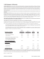
The limited warranty periods for Thermal products shall be as follows (with the exception of XL Plus Series, CutMaster Series , Cougar
and DRAG-GUN): A maximum of three (3) years from date of sale to an authorized distributor and a maximum of two (2) years from
date of sale by such distributor to the Purchaser, and with the further limitations on such two (2) year period (see chart below).
The limited warranty period for XL Plus Series and CutMaster Series shall be as follows: A maximum of four (4) years from date
of sale to an authorized distributor and a maximum of three (3) years from date of sale by such distributor to the Purchaser, and
with the further limitations on such three (3) year period (see chart below).
The limited warranty period for Cougar and DRAG-GUN shall be as follows: A maximum of two (2) years from date of sale to an
authorized distributor and a maximum of one (1) year from date of sale by such distributor to the Purchaser, and with the further
limitations on such two (2) year period (see chart below).
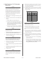
Parts
PAK Units, Power Supplies
XL Plus &
CutMaster Series
Parts
Cougar/Drag-Gun
Parts
All Others
Labor
Main Power Magnetics
3 Years
1 Year
2 Years
1 Year
Original Main Power Rectifier
3 Years
1 Year
2 Years
1 Year
Control PC Board
3 Years
1 Year
2 Years
1 Year
All Other Circuits And Components Including,
But Not Limited To, Starting Circuit,
Contactors, Relays, Solenoids, Pumps,
Power Switching Semi-Conductors
1 Year
1 Year
1 Year
1 Year
1 Year
1 Year
1 Year
1 Year
1 Year
1 Year
Consoles, Control Equipment, Heat
Exchanges, And Accessory Equipment
1 Year
Torch And Leads
Maximizer 300 Torch
SureLok Torches
1 Year
All Other Torches
180 Days
180 Days
180 Days
180 Days
90 Days
90 Days
90 Days
None
Repair/Replacement Parts
Warranty repairs or replacement claims under this limited warranty must be submitted by an authorized Thermal Dynamics® repair
facility within thirty (30) days of the repair. No transportation costs of any kind will be paid under this warranty. Transportation charges
to send products to an authorized warranty repair facility shall be the responsibility of the customer. All returned goods shall be at the
customer’s risk and expense. This warranty supersedes all previous Thermal warranties.
Effective: November 15, 2001
GENERAL INFORMATION
1-8
Date: November 15, 2004
SECTION 2:
INTRODUCTION
2.01 Scope Of Manual
This Manual provides Service Instructions for Thermal
Dynamics PAK Master® 150XL Automated Plasma Power
Supply.
Refer to Operating Manual (0-2824) for individual operating procedures. Information in this edition is therefore
particularly applicable to the Troubleshooting and Repair
of the equipment, and is intended for use by properly
trained Service Technicians familiar with this equipment.
2.03 Service Responsibilities
The Service Technician should be familiar with the equipment and its capabilities and should be prepared to recommend arrangements of components which will provide the most efficient layout, utilizing the equipment to
its best possible advantage.
Maintenance work should be accomplished in a timely
manner. If problems are encountered, or the equipment
does not function as specified, contact Technical Services
Department at West Lebanon for assistance.
Read this manual and the Operating Manual thoroughly.
A complete understanding of the capabilities and functions of the equipment will assure obtaining the performance for which it was designed.
2.02 General Service Philosophy
Several key points are essential to properly support the
application and operation of this equipment.
A. Application
The equipment should satisfy the customer’s requirements as supplied and as described in Section 3 of this
manual. Be sure to confirm that the equipment is capable
of the application desired.
B. Modifications
No physical or electrical modifications other than selection of standard options and accessories are to be made
to this equipment.
C. Customer/Operator Responsibilities
It is the customer/operator's responsibility to maintain
the equipment and peripheral accessories provided by
Thermal Dynamics in good operating order in accordance
with the procedures outlined in the Operating Manual,
and to protect the equipment from accidental or malicious damage.
D. Repair Restrictions
The electronics consists of Printed Circuit Board Assemblies which must be carefully handled, and must be replaced as units. No replacement of printed circuit solder-mounted components is allowed except as noted in
this manual.
Printed Circuit Board Assemblies to be returned must be
properly packaged in protective material and returned
intact per normal procedures.
Manual 0-2825
2-1
INTRODUCTION
INTRODUCTION
2-2
Manual 0-2825
SECTION 3:
DESCRIPTION
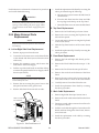
Power Supply
3.01 Scope of Manual
The information in this section has two purposes:
• To familiarize the service technician with the capabilities and limitations of the equipment,
TM
TM
Torch & Leads
• To provide an overall understanding which will allow the technician, in turn, to properly train
customer's operating personnel.
3.02 Power Supply General
Description
A-02862
Work Cable With
Ring Lug
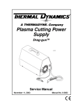
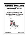
Power Supply is designed to cut most metals up to 1-1/2
inches (38 mm) using air, nitrogen, or argon/hydrogen
as the plasma gas. This system is also capable of satisfying many mechanized gouging applications.
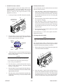
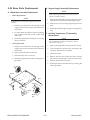
Figure 3-1 Automated Pak Master 150XL System
The Automated Power Supply provides 120 amp maximum output current and includes all control circuitry,
electrical and gas inputs and outputs, pilot circuitry, torch
leads receptacle and a 20 ft (6.1 m) work cable with ring
lug.
The Extra-CoolTM Coolant supplied with the Power Supply can
be used in ambient temperatures down to 10° F (-12° C). For
lower temperatures, Ultra-CoolTM Coolant should be used. This
coolant can be used in areas where the ambient temperature
drops to -27° F (-33° C).
The torch used with the Power Supply is available in the
following configuration:
A. Typical System
• 180° Machine Torch Head (PCM) with 1-3/8 inch
(34 mm) diameter Mounting Tube with Rack and
Pinion Assembly
Automated system include a machine torch with shielded
leads and a CNC Interface Cable.
A typical system configuration will contain the following:
• Automated Power Supply
• 20 ft (6.1 m) Work Cable with Ring Lug
• PCM Torch with 25 ft (7.6 m) or 50 ft (15.2 m) Leads
length as ordered
NOTES
• PCM Torch Spare Parts Kit
The power supply can be ordered in various configurations with various options factory installed.
• CNC Interface Cable, 25 ft (7.6 m) or 50 ft (15.2 m)
length as ordered
Refer to the supplied Torch Instruction Manual for
more information on the Torch.
• Standard Thermal Arc Coolant - 3 gallons (11.4 liters)
Refer to Section 3.04 for list of Power Supply Options and Accessories.
NOTE
Refer to Section 3.04 for complete list of Power Supply Options and Accessories.
B. Requirements to Complete System
To complete the system, the user needs to provide the
following:
• Primary Input Power Cable
• Gas Supplies
Manual 0-2825
3-1
DESCRIPTION
7. Cut Capacity on Carbon Steel
3.03 Specifications/Design
Features
• Genuine Cut Capacity: 1-1/2 inch (38 mm)
• Severance Cut: 1- 3/4 inch (44 mm)
A. Power Supply Specifications
The following specifications apply to the Power Supply
only:
• Pierce Rating: 5/8 inch (15.9 mm)
8. Pilot Circuitry
Capacitive Discharge (CD), Pulsed DC
1. Front Panel Controls
9. CNC Interface Signals
• ON/OFF and RUN/SET Switches
Start/Stop, OK-To-Move and Arc Voltage
• Output Current Control
10. Coolant Pressure
• Work Cable Connection
• Torch Leads Connection
2. Front Panel LED Indicators
Internal Service Adjustable (Factory Only)
130 psi (8.8 bar) at zero flow
• AC
120 - 125 psi (8.2 - 8.5 bar) at 0.6 gpm (2.3 lpm)
• TEMP
11. Coolant Flow Rate
• GAS Pressure/Coolant Flow
0.5 gpm (1.9 lpm) with 150 feet (45.7 m) of total torch
and torch leads at 70°F (21°C)
• DC Output
3. Rear Panel
NOTE
• Primary Input Power Cable Strain Relief
The flow rate varies with lead length, torch configuration, ambient temperature, amperage level,
etc.
• Plasma Gas Supply Connection
• Plasma Gas Regulator/Filter Assembly with Gas
Pressure Gauge and Pressure Adjustment
• Secondary Gas Supply Connection
12. Cooling Capacity
4,000 to 10,000 BTU
• Secondary Gas Regulator/Filter Assembly with Gas
Pressure Gauge and Pressure Adjustment
NOTE
• Two Stage Air Line Filter
• CNC Control Connector
4. Input Power (see NOTES)
Maximum value based on “free flow” condition.
13. Coolant Reservoir Capacity
208/230/460 VAC (±10%), 50/60 Hz, Three-Phase
2 gallons (Use Thermal Arc® coolant only)
220/380-415 VAC (±10%), 50/60 Hz, Three-Phase
Capable of handling a total of 150 feet (45.7 m) of torch
lead length
575 VAC (±10%), 50/60Hz, Three-Phase
14. Overall Dimensions
NOTES
Height: 45-3/8 inches (1.2 m)
Refer to Appendix 1 for suggested input wiring
size, current ratings and circuit protection requirements.
Units using 575 VAC input power require installation of Optional 575V Transformer Assembly.
Width: 24-1/2 in (0.6 m)
Depth: 35 inches (0.9 m)
15. Weight
Power Supply with Torch: 275 lbs (125 kg)
5. Output Power
Shipping Weight: 350 lbs (158.8 kg)
Continuously variable from 30 to 120 amps (±5%)
6. Duty Cycle
16. Used With Torch
• PCM-120 Automated Machine Torch
60% @ 128 vdc output at 120 amps
DESCRIPTION
3-2
Manual 0-2825
B. Gas Regulator/Filter Assembly
Specifications
The following specifications apply to the Gas Regulator/
Filter Assembly only:
1. Gas Regulator Maximum Gauge Pressure
Plasma: 160 psi (11.3 bar)
3.04 Power Supply Options and
Accessories
The following accessories are available for the Power
Supply. Refer to Section 6, Parts Lists, for part numbers
and ordering information.
A. Primary Input Power Cable
Secondary: 160 psi (11.3 bar)
The following input power cables are available:
2. Maximum Input Gas Pressure
• 230VAC, (2AWG) 10 ft (3 m)
125 psi (8.6 bar)
• 460VAC, (6AWG) 10 ft (3 m)
B. High Pressure Regulators
3. Filter
High pressure regulators are available for air, nitrogen, and argon-hydrogen. The regulators are used to
set the proper pressure for the type of gas being used.
Coalescent type filter
C. Gas Requirements
1. Plasma
C. 575V Transformer
Gases: Compressed Air, Nitrogen, Argon/Hydrogen
This 575 VAC to 460 VAC Step-down Transformer allows the Power Supply to operate on 575 VAC threephase input power.
Operating Pressure: 65 psi (4.5 bar)
Cold Flow:
D. Standoff Control (SC11)
Cutting: 50 - 78 scfh (23.6 - 36.8 lpm)
Optional Standoff Control automatically finds height
and maintains torch standoff with a high speed torch
lifter motor. Refer to Standoff Control (SC11) Manual,
0-2556, for more information.
Gouging: 85 - 95 scfh (40.1 - 44.8 lpm)
CAUTION
Maximum input gas pressure must not exceed 125
psi (8.6 bar).
E. Remote Pendant Control
Control used to manually start and stop cutting operations from a location up to 20 ft. (6.1 m) from the
Plasma Power Supply.
2. Secondary
Gases: Compressed Air, Carbon Dioxide (C02), Nitrogen
Operating Pressure: 60 psi (4.1 bar)
Cold Flow:
Cutting: 340 scfh (160.4 lpm)
Gouging: 235 scfh (110.9 lpm)
CAUTION
Maximum input gas pressure must not exceed 125
psi (8.6 bar).
D. Two Stage Air Line Filter
The Two Stage Air Line Filter will remove moisture
and contaminants from the air stream when using
compressed air. The filter is capable of filtering to at
least 5 microns.
Manual 0-2825
3-3
DESCRIPTION
F. Interlocks
2.05 Theory Of Operation
A. Plasma Arc Cutting and Gouging
Plasma is a gas which is heated to an extremely high temperature and ionized so that it becomes electrically conductive. The plasma arc cutting process uses this plasma
gas to transfer an electric arc to a workpiece. The metal
to be cut is melted by the intense heat of the arc and then
blown away by the flow of gas.
The system has several built-in interlocks to provide safe
and efficient operation. When an interlock shuts down
the system, the fault condition must be remedied and the
system recycled using the applicable control device.
1.
The Power Supply has a built-in parts-in-place interlock that prevents accidental torch starting
when torch parts are not properly installed. A flow
switch on the coolant return lead detects reduced
coolant flow caused by improper torch assembly.
If not satisfied, the switch interrupts power to the
tip and electrode.
With a simple change of torch parts, the system can also
be used for plasma arc gouging. Plasma arc gouging uses
the same process to remove material to a controlled depth
and width.
B. Input and Output Power
2.
The unit converts AC input power to DC power for the
main cutting arc. The negative output is connected to
the torch electrode through the negative torch lead, and
the positive output connects to the workpiece through
the work cable.
C. Pilot Arc
When the torch is activated there is a 2 second (service
adjustable) gas pre-flow, followed by an uninterrupted
pulsed DC pilot arc established between the electrode and
tip. The pilot arc is initiated by a momentary high frequency pulse from the Power Supply. The pilot creates a
path for the main arc to transfer to the work. When the
main arc is established, the pilot arc shuts off. The pilot
automatically restarts when the main arc stops, as long
as the torch remains activated.
Parts-In-Place (PIP) Interlock
Gas Pressure Interlock
A pressure switch acts as an interlock for the
plasma gas supply. If the plasma gas supply pressure falls below minimum requirements the pressure switch will open, shutting off the power to
the contactors, and the GAS indicator will go out.
When adequate plasma supply pressure is available the pressure switch will close, allowing power
to be resumed for cutting.
NOTE
There is no gas pressure interlock for secondary
gas.
D. Main Cutting Arc
The power supply converts the AC input power to DC
power for the main cutting arc. The negative output is
connected to the torch electrode through the negative
torch lead. The positive output is connected to the workpiece via the work cable and clamp connection.
E. RF Shielding
Automated systems using CNC Interface Cables are
shielded to minimize radio frequency (RF) interference
which results from the high frequency arc initiation. These
shielded systems are designed with features such as a
wire for establishing an earth ground and shielded torch
and control leads. The CNC control signals are filtered
on an internal PC Board.
DESCRIPTION
3-4
Manual 0-2825
SECTION 4:
SERVICE
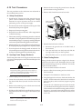
4.01 Introduction
C. Power Supply Cleaning
To clean the unit, open the enclosure and use a vacuum
cleaner to remove any accumulated dirt and dust. The
unit should also be wiped clean. If necessary, solvents
that are recommended for cleaning electrical apparatus
may be used.
This Section provides service diagnostics for the Automated Pak Master 150XL Power Supply, allowing the Technician to isolate any faulty subassemblies. Refer to Section 5, Repairs & Replacement Procedures, for parts
replacement instructions.
WARNING
Do NOT blow air into the power supply during
cleaning; make sure to always blow air out of the
unit. Blowing air into the unit can cause metal
particles to interfere with sensitive electrical components and cause damage to the unit.
Under no circumstances are field repairs to be attempted
on Printed Circuit Boards or other subassemblies of this
unit. Evidence of unauthorized repairs will void the factory warranty.
NOTE
The troubleshooting contained in this manual is for
the Power Supply only. Troubleshooting other
parts of the system is covered in the separate manuals for that product.
4.02 Periodic Inspection &
Procedures
NOTE
Refer to Appendix 13 for a recommended maintenance schedule for water cooled plasma cutting
systems.
While the side panels are off, inspect the wiring in the
unit. Look for any frayed wires or loose connections that
should be corrected.
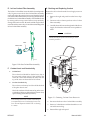
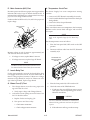
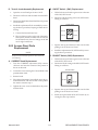
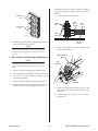
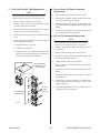
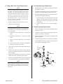
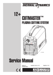
D. Coolant Filter Assembly
The Coolant Filter Screen should be cleaned periodically.
To gain access to the Coolant Filter Assembly, remove the
right side panel when viewed from front of unit. Remove
the Filter Screen by unscrewing the filter holder from the
Coolant Filter Assembly. Clean the filter screen by rinsing with hot soapy water. Remove soap residue by rinsing with clean hot water. Be sure that all the soap has
been removed and the screen is dry of water before reinstalling in the Coolant Filter Assembly.
This subsection describes inspection procedures which
should be performed at periodic intervals as required.
A. Physical Inspection
Check that all cable connections are secure.
B. Fan Motor and Pump Lubrication
The fan motor and pump in the power supply should
be oiled twice per year or once for each 100 hours of
operation. To oil the motor, remove one side panel
and add two or three drops of 20 SAE oil to the front
and rear oil holes on the motor.
Filter
NOTE
Some units may utilize a sealed motor design which
does not require lubrication.
Filter Holder
A-02152
Figure 5-1 Coolant Filter Assembly
Manual 0-2825
4-1
SERVICE
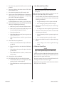
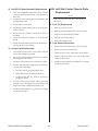
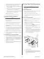
E. In-Line Coolant Filter Assembly
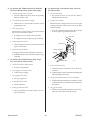
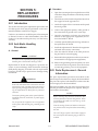
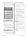
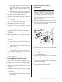
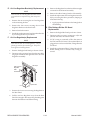
G. Draining and Replacing Coolant
The In-line Coolant Filter Screen should be cleaned periodically. To gain access to the In-Line Coolant Filter Assembly
remove the right side panel (when viewed from the front of
unit). Remove the Filter Screen by unscrewing the Filter Holder
from the In-Line Coolant Filter Assembly. Clean the Filter Screen
by rinsing with hot soapy water. Remove soap residue by
rinsing with clean hot water. Be sure that all the soap has been
removed and the screen is dry of water before reinstalling in the
In-Line Coolant Filter Assembly.
Remove the old coolant from the Power Supply reservoir
as follows:
1.
Remove the right side panel from the Power Supply.
2.
Disconnect the coolant input hose to the Coolant
Filter Assembly.
3.
Carefully lower the hose out the right side of the Power
Supply and drain the coolant into an acceptable container.
CAUTION
Handle and dispose of the used coolant per recommended procedures.
Filter
Filter Holder
Coolant
Filter
Assembly
A-02153
Figure 5-2 In-Line Coolant Filter Assembly
F. Coolant Level and Conductivity
1.
Coolant
Reservoir
Coolant Level
Coolant
Input Hose
The coolant level should be checked every day at
the rear panel coolant gauge. If the coolant in the
reservoir is more than 2 inches (50 mm) from the
top of the reservoir then add Torch Coolant.
2.
Coolant Conductivity
The coolant conductivity level should be checked
if the pilot doesn't start.
A-02878
Check the condition of the deionizer bag in the reservoir basket, if the bag is yellowish brown (straw color)
replace the bag and coolant (see NOTE).
NOTE
Figure 5-3 Draining Coolant From Reservoir
To accurately measure the coolant conductivity it
is recommended to use a Conductivity Sensor similar to Thermal Dynamics Model TDS-73 (Catalog
# 7-2844).
SERVICE
4-2
4.
Reconnect the hose to the Coolant Filter Assembly.
5.
Remove Coolant Reservoir lid and install new coolant and deionizer bag.
6.
Reinstall the right side panel.
Manual 0-2825
The resulting current is sensed by the Current Sense
PC Board, resulting in the demand level changing from
pilot current to whatever the main current control is
set at. During the "transfer" the CSR Indicator (D65)
comes ON and the transfer enable signal goes low allowing the bottom gate drive and FET modules to come
up and start running. Also at this time, D5 (located on
the Pilot Output PC Board) shuts off and at this time
the main cutting arc is initiated. If the torch is removed
from the workpiece, the pilot arc will automatically
restart if the START signal is still active.
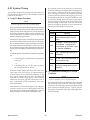
4.03 System Theory
The system is designed for mechanized (automated) cutting operations using the torch control bulkhead and rear
panel as the interface.
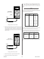
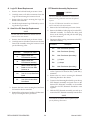
A. Logic PC Board Functions
NOTE
Refer to Appendix 4 for Logic PC Board layout.
The Logic PC Board controls the timing and sequencing of
the system. It monitors the pressure, temperature, and flow
interlocks and controls the gas flow in run and set modes
by turning on the plasma and secondary solenoids. The
Logic PC Board also controls the power on the voltage
selection and prepurge functions.
Logic PC Board
Indicator
After the ON/OFF switch is closed on the front panel, the
AC Indicator blinks and the GAS Indicator is ON steady.
The AC Indicator blinks for approximately 8 seconds then
at that time it becomes steady and the inrush relay closes.
The GAS Indicator stays ON for approximately 20 seconds
(prepurge function) then goes OFF and the gas stops flowing.
The START signal is activated by one of the following methods:
• Connecting J22-3 to J22-4 at the rear panel CNC
connector
D26
START Signal Enable - When ON
(start) indicates START signal is
active.
D25
CD Enable - Initiates spark gap on
CD PC Board. Indicator should
come ON then go OFF after a pilot
arc has been established.
D65
CSR - Indicates main cutting arc is
established.
D47
AC OK - When ON indicates that AC
Input voltage is okay.
D31
Drag - When ON indicates that the
torch tip is making contact with the
workpiece.
- or • Connecting TB-1 pin 3 to TB-1 pin 4 on the Filter/Voltage Divider PC Board
When the START signal is activated, D26 "start" Indicator comes ON, gas will flow for approximately 2
seconds before DC is established (indicated on the
front panel). During this time D25 CD Enable will
come ON and sends a logic signal to the CD Board
which fires the spark gap and initiates the torch to
pilot. D25 should go OFF immediately if the pilot
starts immediately.
B. CD (Capacitive Discharge) PC Board
Functions
NOTE
Refer to Appendix 7 for CD PC Board layout.
The CD Board functions are initiated by the CD Enable
signal from the Logic PC Board. The CD arc starting
circuit fires the spark gap producing the high voltage
spark which starts the DC pilot arc. When a pilot arc
is sensed by the Gate Drive Board, the PSR signal shuts
off the CD enable.
When the torch is close to the workpiece, the cutting arc
"transfers" to the work. Also, if the tip touches the workpiece, the current is automatically folded back to approximately 35 amps to save the tip from being blown out.
Manual 0-2825
Meaning
4-3
SERVICE
C. Gate Drive PC Board Functions
E. Current Sense PC Board Functions
NOTE
NOTE
Refer to Appendix 5 for Gate Drive PC Board layout.
Refer to Appendix 11 for Current Sense PC Board
layout.
This board controls the amount of time the FETs are turned
on. This is done with a pulse width modulator (PWM)
controlled by the demand signal from the Logic PC Board
(The longer the FETs are on, the more output current). If a
short develops, the primary overcurrent will shut down the
gate drive and not allow the power supply to power up and
run.
This board senses current in the work lead (approximately 3 amps). When this happens, it sends a signal
back to the Logic Board. This in turn tells the Logic to
change demand levels from pilot current to main cutting current.
F. Filter/Voltage Divider PC Board Functions
NOTE
The PSR signal senses any current in the secondary and
determines what the PWM should do for a pulse width. If
there is current in the secondary, the PSR signal will go
back to the Logic PC Board and shut off the CD Enable
signal.
Refer to Appendix 18 for Filter/Voltage Divider
PC Board Diagram.
The Filter/Voltage Divider PC Board provides common mode inductors for all the Remote (J22) CNC signals that require filtering. These inductors, in series
with the control signals, work with the capacitance
between the control signal lines of the CNC (remote
control) cable and the cable shield to form an LC (inductive/capacitive) lowpass filter. To obtain the required capacitance for the lowpass filter to work, the
CNC cable shield must be terminated to ground
(grounded chassis) at the cutting machine end of the
cable.
Gate Drive PC Boards
Indicator
D4
D20
Meaning
Power Enable - When ON PWM
Enable received from the Logic
PC Board.
Reset - Normally ON, goes out
when torch switch is pressed.
Indicator will blink if primary overcurrent is detected when torch
switch is pressed.
The Filter/Voltage Divider PC Board also contains the
voltage divider circuit for the SC11 Standoff Control.
The voltage divider converts and filters the high negative arc voltage to a lower positive signal used by the
SC-11 Standoff Control. Arc voltage plus (+) and minus (-) with 100K ohm series resistors are also provided for use by certain other standoff controls.
D. Pilot/Output PC Board Functions
NOTE
Refer to Appendix 6 for Pilot/Output PC Board
layout.
This board has an IGBT which is turned on by the
Logic Board for piloting. This allows the DC to flow
from the output (-) through the pilot return (tip) to a
Pilot Inductor and finally to the work. This path is
broken very quickly by the IGBT when the main cutting arc is initiated. This board also filters the torch
shield back to the torch (-) through the Capacitor.
Indicator
D5
SERVICE
Pilot PC Board
Meaning
IGBT is turned on from the logic signal
coming from the Logic Board PCR J5-6.
NOTE: This LED is on during piloting; it is
off during cutting.
4-4
Manual 0-2825
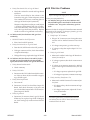
4.04 Common Operating Problems
E. Dross
When dross is present on carbon steel, it is commonly
referred to as either “high speed, slow speed, or top
dross”. Dross present on top of the plate is normally
caused by too great a torch to plate distance. "Top
dross" is normally very easy to remove and can often
be wiped off with a welding glove. "Slow speed dross" is
normally present on the bottom edge of the plate. It can
vary from a light to heavy bead, but does not adhere tightly
to the cut edge, and can be easily scraped off. "High speed
dross" usually forms a narrow bead along the bottom of the
cut edge and is very difficult to remove. When cutting a
troublesome steel, it is sometimes useful to reduce the cutting speed to produce "slow speed dross". Any resultant
cleanup can be accomplished by scraping, not grinding.
WARNINGS
Disconnect primary power at the source before disassembling the power supply, torch, or torch leads.
Frequently review the Important Safety Precautions in Section 1. Be sure the operator is equipped
with proper gloves, clothing, eye and ear protection. Make sure no part of the operator’s body comes
into contact with the workpiece while the torch is
activated.
CAUTION
F. Common Cutting Faults
1. Insufficient Penetration
Sparks from the cutting process can cause damage to coated, painted, and other surfaces such as
glass, plastic and metal.
a. Cutting speed too fast
b. Torch tilted too much
NOTE
c. Metal too thick
Handle torch leads with care and protect them from
damage.
d. Worn torch parts
e. Cutting current too low
A. Piloting
Piloting reduces parts life more than actual cutting
because the pilot arc is directed from the electrode to
the tip rather than to a workpiece. Whenever possible,
avoid excessive pilot arc time to improve parts life.
f.
2. Main Arc Extinguishes
a. Cutting speed too slow
b. Torch standoff too high from workpiece
B. Torch Standoff
Improper standoff (the distance between the torch tip
and workpiece) can adversely affect tip life as well as
shield cup life. Standoff may also significantly affect
the bevel angle. Reducing standoff generally results
in a more square cut.
Drag cutting above 35 amps ("Tip Saver Circuit")
c. Cutting current too high
d. Work cable disconnected or bad connection
e. Worn torch parts
3. Excessive Dross Formation
a. Cutting speed too slow
C. Edge Starting
b. Torch standoff too high from workpiece
For edge starts, hold the torch perpendicular to the
workpiece with the front of the torch tip at the edge
of the workpiece, not touching, at the point where the
cut is to start. When starting at the edge of the plate,
do not pause at the edge and force the arc to “reach”
for the edge of the metal. Establish the cutting arc as
quickly as possible.
c. Worn torch parts
d. Improper cutting current
e. Improper gas selection for cutting material
D. Direction of Cut
The plasma gas stream swirls as it leaves the torch.
The purpose of the swirl is to maintain a smooth column of gas. The swirl effect results in one side of a
cut being more square than the other. Viewed along
the direction of travel, the right side of the cut is more
square than the left.
Manual 0-2825
4-5
SERVICE
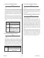
The troubleshooting guide has six subsections as follows:
4. Short Torch Parts Life
a. Oil or moisture in air source
Section 4.06 - Circuit Fault Isolation
b. Exceeding system capability (material too thick)
Section 4.07 - Main Input and Internal Power Problems
c. Excessive pilot arc time
Section 4.08 - Pilot Arc Problems
d. Air flow too low (incorrect pressure)
Section 4.09 - Main Arc Problems
e. Improperly assembled torch
f.
Section 4.10 - Test Procedures
Incorrect torch parts for the operation
g. Non-Genuine Thermal Dynamics parts used
4.05 Troubleshooting Guide General Information
WARNING
There are extremely dangerous voltage and power
levels present inside this unit. Do not attempt to
diagnose or repair unless you have had training in
power electronics measurement and troubleshooting techniques.
C. How to Use the Troubleshooting Guide
The following information is a guide to help the Service
Technician determine the most likely causes for various
symptoms. This guide is set up in the following manner:
1. Perform operational check(s) on the equipment to isolate problem to possible circuit(s) per Section 4.06, Circuit Fault Isolation. Refer to the Appendix Pages for
PC Board layouts, as necessary.
2. Determine symptom and isolate to defective assembly
using the following format:
X. Symptom (Bold Type)
Any Special Instructions (Text Type)
1. Cause (Italic Type)
A. Basic Troubleshooting
a.
For basic troubleshooting and parts replacement, refer to
Operating Manual. This manual should be your first resource for troubleshooting. If the problem cannot be remedied using the Operating Manual, refer to the advanced
troubleshooting in this Service Manual.
a. Locate your symptom in the appropriate subsection.
b. Check the causes (easiest listed first) for the
symptom.
B. Advanced Troubleshooting
This manual provides advanced troubleshooting and
parts replacement not covered in the basic troubleshooting section of the Operating Manual. In most cases, it
requires Power Supply disassembly and live measurements.
Check/Remedy (Text Type)
c. Check the remedies listed for each cause.
3. Repair as needed being sure to verify that unit is fully
operational after any repairs.
NOTES
Many signals are transferred between Printed Circuit Board Assemblies on Ribbon Cables. If these
cables become faulty they can then cause various
problems. Do not forget about these cables when
troubleshooting.
Troubleshooting and repair of this unit is a process which
should be undertaken only by those familiar with high
voltage high power electronic equipment.
If major complex subassemblies are faulty, the faulty subassembly must be returned for repair.
While troubleshooting visually inspect the internal
components for signs of overheating, fractures and
damage.
NOTE
Follow all instructions as listed and complete each
in the order presented.
Subsection 4.09 includes specific test procedures and LED
status identification tables. The subsection is referenced
by the troubleshooting guide for the specific test to be
performed.
SERVICE
4-6
Manual 0-2825
4.06 Circuit Fault Isolation
Set the Power Supply RUN/SET switch to the RUN position and note the following:
This section is used before troubleshooting to help isolate
the defective circuit, identify symptoms, and test the unit
for proper operation.
•
Gas Indicator goes OFF
•
Gas flow stops
NOTE
NOTE
Follow all instructions as listed and complete each
in the order presented.
This unit has a 20 second pre-purge feature which begins
when the unit is turned ON. As long as the RUN/SET
Switch is in the SET position, the gas will flow indefinitely. However, once the RUN/SET Switch is placed in
the RUN position, the gas will stop flowing after approximately 20 seconds (The 20 seconds begins from the
time the unit is turned on, not from when the unit was put
in the RUN position.)
Follow the instructions as given to identify the possible
symptom(s) and the defective circuit. After repairs are
complete then run the following tests again to verify that
the unit is fully operational.
A. Initial Setup Conditions
Connect gas supply to rear of Power Supply.
Turn on gas supply and adjust the Plasma Gas Regulator to 65
psi (4.5 bar) and the Secondary Gas Regulator to 60 psi (4.1
bar).
Set the Power Supply controls as follows:
This completes the Main Input and Internal Power Tests.
If the unit functions as described above, and all correct
then proceed to the Pilot Arc Test below.
If the unit does not function as noted then note the symptom and proceed to Section 4.07, Main Input and Internal Power Problems.
ON/OFF switch to OFF
C. Pilot Arc Test
RUN/SET switch to SET
Activate START signal from CNC or press the torch switch
on the Remote Pendant to establish a pilot arc and note
the following:
CURRENT control potentiometer to maximum
B. Main Input and Internal Power Tests
Connect main AC power to the unit.
Set the Power Supply ON/OFF switch to ON and note the following:
•
•
AC indicator blinks for eight (8) seconds, then steady
ON
Main Contactor energizes (clicks once) while AC Indicator is blinking
•
Inrush Relay energizes (clicks once) after AC Indicator stops blinking
•
TEMP Indicator OFF
•
GAS Indicator ON
•
Gas flows
•
Fans operate
•
DC Indicator OFF
Manual 0-2825
•
Gas flows
•
GAS indicator turns ON
•
After preflow delay DC indicator turns ON
•
Pilot arc established
This completes the Pilot Arc Test. If the above are all correct then proceed to the Main Arc Test below.
If the above does not function as noted then note the symptom
and proceed to Section 4.08, Pilot Arc Problems.
4-7
SERVICE
C. AC indicator on front panel of power supply is OFF
D. Main Arc Test
1. Front Panel ON/OFF switch in OFF position
Activate START signal from CNC or press the torch switch
on the Remote Pendant to establish a pilot arc.
a. Place switch to ON position
Bring the torch to within 1/8"-3/8" (3.2 - 9.5 mm) of the
workpiece to establish the main cutting arc, and note the
following:
•
2. Main power disconnect not closed
a. Close main power disconnect
Main cutting arc initiates
3. Main power line fuses blown
This completes the Main Arc Test. If the above are all
correct then the equipment should be operating properly.
If problems still persist then contact Technical Services.
a. Replace main power line Fuses
4. Defective input power cable
a. Replace input power cable
If the above does not function as noted then note the
symptom and proceed to Section 4.09, Main Arc Problems.
5. Improper input power line connections inside Power
Supply
a. Refer to Operating Manual, Section 3.07, Input
Power Cable Connections, and correct connections if necessary
4.07 Main Input and Internal Power
Problems
NOTES
6. Fuse blown inside Power Supply
The Input PC Board has a neon light on the upper
left hand corner. If AC power is present on L1, L2,
L3 of the Main Contactor, the light will be on.
a. Replace internal Fuse (F1)
7. Voltage selection plug connected incorrectly
a. Refer to Operating Manual, Section 3.06 and
correct as needed
Refer to the Appendix Pages for PC Board Layouts, as required.
8. Faulty Auxiliary Transformer (refer to Appendix 12,
36 VAC Circuit Diagram)
Locate your symptom below:
A. Main power line fuses blow as soon as main
disconnect is closed
Measure for 36 VAC on Logic PC Board from J1-1
to J1-5.
1. Input power cable installed incorrectly
a. If voltage is not present, replace the Auxiliary
Transformer
a. Refer to Operating Manual, Section 3.07, Input
Power Cable Connections, and connect input
cable
9. Faulty ON/OFF switch (refer to Appendix 12, 36 VAC
Circuit Diagram)
B. Main power line fuses blow when unit is powered on
Measure for 36VAC on the Logic PC Board between J3-2 to J3-4.
1. Input Bridge Faulty
a. If voltage is not present replace the ON/OFF
switch
a. Test Input Bridge Rectifier per Section 4.10-D;
repair as necessary
10. Faulty Logic PC Board (refer to Appendix 12, 36 VAC
Circuit Diagram)
2. Faulty FET/Heatsink Assembly
a. Check per Section 4.10-K; repair as necessary
Measure for 36 VAC on Logic PC Board from J5-1
to J5-3.
3. Faulty Input PC Board
a. If voltage is not present, replace the Logic PC
Board
a. Test Input PC Board per Section 4.10-D; repair
as necessary
SERVICE
4-8
Manual 0-2825
D. AC indicator ON, TEMP indicator ON, RUN/SET
Switch is in RUN position, System will not pilot
F. AC indicator ON; GAS indicator OFF; Gas flows;
DC indicator OFF
1. Air flow through unit is restricted
1. Gas pressure too low
a. Provide adequate air flow (refer to Operating
Manual, Section 3.02)
a. Set pressures above 35 psi (2.4 bar) limit of
Plasma Pressure Switch
2. Exceeded duty cycle of Power Supply
2. Faulty pressure switch
a. Wait for fans to cool unit (refer to Section 3.03 for
proper Duty Cycle)
Measure for DC voltage from wire #51 to wire #50
at the gas Pressure Switch at the rear of the Rear
Panel Assembly.
3. Fans not operating
a. If 12 vdc is present and pressure is above 35 psi
(2.4 bar), replace gas Pressure Switch.
Measure for 115 VAC on the Logic PC Board from
J96-1 to J96-3 and J96-2 to J96-4.
• If voltage is correct, replace Fan Assembly
Rear Panel
• If voltage is incorrect, replace Logic PC Board
4. Faulty temperature circuit
Gas Solenoid
a. Check temperature circuit per Section 4.10-H;
repair as necessary
5. Defective Logic PC Board
Gas Pressure Switch
On Logic PC Board remove J4 and J2 connectors
Wire #51
a. If TEMP Indicator stays ON then replace Logic
PC Board
E. AC indicator ON; TEMP indicator OFF; No gas
flow; GAS and DC indicators OFF
Wire #50
1. RUN/SET switch in RUN position
3. Low or No Coolant Flow
a. Switch to SET position
a. Check for proper coolant level. If low, fill to correct level.
2. Gas supply not connected to unit
b. Check pump for proper operation (running) and
replace pump if necessary.
a. Connect to gas supply
3. Gas supply not turned on
4. Clogged coolant filter and/or in-line coolant filter
a. Turn gas supply on
a. Check internal and external coolant filters. Clean
or replace if necessary. Flush the old coolant from
the system.
4. Faulty RUN/SET switch
a. Check continuity
5. Clogged torch leads
5. Faulty gas solenoid circuit
a. Check torch and leads and replace if necessary.
Flush the old coolant from the system.
a. Test gas solenoid circuit per Section 4.10-I; repair as necessary
Manual 0-2825
A-01184
4-9
SERVICE
6. Faulty Flow Switch (FS1) or Logic PC Board
4.08 Pilot Arc Problems
a. Check the coolant flow switch and Logic Board
as follows:
The flow switch (FS1) for the coolant is calibrated for 0.25 gpm. When adequate coolant
flow satisfies FS1, it closes, connecting J99-1 on
the Logic PC Board to J99-3 (common).
Measure voltage between J99-pin 1 and J99-pin
3. If J99-1 is greater than 2 volts, FS1 or connections to FS1 are faulty. If the voltage is less than
2vdc, the Logic Board may be faulty. Replace
the flow switch or Logic Board as necessary.
NOTE
Refer to the Appendix Pages for PC Board Layouts.
Locate your symptom below:
A. AC Indicator ON; gas flows; GAS Indicator ON
when START signal is activated; DC Indicator OFF
or flashes once. No spark or momentary spark at
torch
Measure for 320 vdc at Input PC Board between terminal
E8 wire #8 to E3 wire #9. If voltage is present, go to #4,
Faulty Logic or Gate PC Board.
G. AC Indicator ON; GAS Indicator ON; gas flows
continually
1. Faulty Input "W" Contactor.
a. If Input "W" Contactor is not closing then measure the coil for 120VAC between wires #55 &
#59.
1. RUN/SET Switch in the SET position.
a. Place Switch in RUN position.
2. Faulty Gas Solenoid(s) or Logic PC Board
• If voltage is not present, go to the next step.
a. Turn the ON/OFF Switch to the OFF position.
• If the gas continues to flow, check the air filters
or replace Solenoid(s).
• If the gas flow stops, replace the Logic PC Board.
H. AC indicator ON; Gas flows; GAS and DC indicators ON; Arc in torch without activating START
signal; D26 (START enable) on Logic PC Board ON
2. Faulty Logic PC Board
a. Measure for 120VAC at the Logic PC Board connector J2-1 and J2-4.
• If voltage is present, then check connections to
"W" coil.
1. Faulty Remote Pendant switch
• If voltage is not present, measure for 120VAC
input to the Logic PC Board between J1-2 and
J1-6.
a. Check continuity
2. Faulty CNC Cable
• If voltage is present, replace the Logic PCB.
a. Disconnect the CNC Cable from the J22 connector. If the arc shuts off, the controller is supplying a START signal.
3. Faulty Pilot Output Board
• If voltage is not present, continue to next step.
3. Faulty Auxiliary Transformer (T3)
a. Measure for 120VAC between T3 connector J302 to J30-6.
a. Turn unit off.
b. Disconnect J12 and J13 from Pilot Output PC
Board, then check continuity at J12 pin 1 and
pin 3 on the Pilot Output Board. If shorted, replace Output PC Board.
4. Faulty Logic Board
• If voltage is okay, check connections to Logic
PC Board.
• If voltage is not present, replace the T3 Auxiliary Transformer.
NOTE
a. Disconnect J5 connector from Logic PC Board.
If D26 stays on, replace Logic PCB. If D26 goes
out, check wiring to J5 connector from Pilot PC
Board.
SERVICE
• If voltage is okay, then replace Input "W" Contactor.
4-10
For #4 through #6 below, J-11 should be disconnected
and isolated from the CD PC Board and the torch
switch will need to be closed.
Manual 0-2825
4. Faulty Logic PC Board or Gate PC Board (see note above)
a. Close the torch switch. The LED D20 on the top
Gate PC Board should turn off.
B. AC indicator ON; Gas flows; GAS indicator ON; DC
indicator blinks; Small arc may be visible in torch
1. Shorted torch
a. Remove torch from bulkhead connections. Measure between Pilot Return Lead and Torch (-). If
the meter doesn't show an open, repair torch.
• If LED D20 does not turn off, measure for 12 vdc
to drop to less than 2 vdc between J9-12 to J9-11.
• If voltage does not drop, replace the Logic PC
Board.
2. Faulty Pilot Output PC Board
a. Test per Section 4.10-J; repair as necessary
• If voltage drops to less than 2 vdc, replace the
Gate Drive PC Board.
3. Faulty FET/Heatsink Assembly
• If LED D20 does turn off, D4 should flash on/off
once two seconds later.
• If D4 does not flash on/off once, measure for
12 vdc to drop to less than 2 vdc momentarily,
between J9-14 to J9-13 on the top Gate Drive
PC Board.
a. Check per Section 4.10-K; repair as necessary
C. AC indicator ON; Gas flows; GAS and DC indicators
ON; No arc in torch; No arc at spark gap on CD PC
Board; CD enable indicator D25 on Logic Board ON
1. Faulty CD PC Board
• If the voltage does not drop momentarily,
then replace the Logic PC Board.
Measure DC voltage between J11-4 to J11-5 on CD PC
Board
• If the voltage does drop momentarily, replace the Gate Drive PC Board.
a. If voltage is less than 2 vdc replace CD PC Board
• If D4 on the Gate PC Board does flash for two
seconds after D20 turns off, then go to the next
step.
D. AC indicator ON; Gas flows; GAS and DC indicators
ON; Spark at gap on CD PC Board and CD enable
indicator (D25) on Logic PC Board ON; No arc or
intermittent arc in torch
1. Gas pressure(s) set incorrectly (too high)
5. Faulty Torch or Leads (see note above)
a. Check gas pressures. Plasma Gas Pressure
should be 65 psi (4.5 bar), and Secondary Gas
Pressure should be 60 psi (4.1 bar).
a. Remove wire 15 from Pilot Output PC Board terminal E24.
b. Following the procedure detailed in 4.10-K.1, measure the output voltage at the FET Heatsink Assembly between E-17 & E-18. If voltage is okay
with wires disconnected, repair or replace torch/
leads as required.
2. Oil/moisture in air lines
a. Purge system. If problem corrected add filters in
line with air source
3. Incorrect torch parts
6. Faulty Output Pilot PC Board (see note above)
a. Refer to appropriate Torch Instruction Manual
a. Test per section 4.10-J. repair as necessary.
4. Faulty leads
b. Disconnect and isolate wires from E8 on Pilot Output PC Board.
a. Check continuity per appropriate Torch Instruction Manual
c. Following the procedure detailed in 4.10-K.1, measure the output voltage at the FET Heatsink assembly between E-17 & E-18. If voltage is okay
with wires disconnected, replace Output Pilot PC
Board.
5. Faulty torch
a. Check continuity per appropriate Torch Instruction Manual
6. Faulty connection of wire #15 or #17 to Pilot Output PC
Board or pilot inductor wires reversed with wire #17.
7. Faulty FET PC Board
a. Check per section 4.10-K. Repair or replace as
necessary.
Manual 0-2825
a. Check wiring connection
4-11
SERVICE
4. Faulty Current Sensor PC Board
7. Faulty Pilot Output PC Board
Check the following:
a. D5 on the Pilot PC Board should turn on two
seconds after the START signal is activated.
a. While trying to initiate main cutting arc, measure the voltage at J99-6 to J99-7 (or TP 10 to
Gnd) indicators inside the Power Supply.
• If D5 does turn ON, install a jumper between
E22 and E8 on the Pilot PC Board. If unit
will pilot with jumper installed, replace the
Output PC Board.
• If voltage is approximately 12 vdc replace
the Current Sensor.
• If D5 does not turn ON, measure the 12 vdc
to drop to less than 2 vdc between J13-18 &
J13-17 two seconds after START signal is activated. If voltage does drop, then measure
for 36 VAC between J13-14 & J13-15. If
36VAC is found then replace the Pilot/Output PC Board.
• If voltage is less than 2 vdc replace the Logic
PC Board.
5. Faulty Transfer Mod Enable Signal
a. Test this Signal by measuring J4-6 to J4-8.
• If voltage approximately 12 vdc, replace Logic
Board
8. Faulty Logic PC Board
a. If the voltage between J13-18 & J13-17 on the
Pilot/Output PC Board does not drop to less
than 2 vdc two seconds after the START signal
is activated, replace the Logic PC Board.
• If 0 vdc, replace Gate Drive Board
B. When operating at amperages over 35 amps the amperage drops off after main cutting arc initiates
Check whether Drag indicator (D31) on the Logic PC Board
is ON when the torch tip comes in contact with the workpiece.
4.09 Main Cutting Arc Problems
NOTE
1. Cutting tip in contact with the workpiece.
Refer to the Appendix Pages for PC Board Layouts.
a. Maintain standoff distance 1/8"-3/8" between
cutting tip and workpiece.
Locate your symptom below:
A. Main cutting arc will not initiate
2. Faulty Logic PC Board
1. Work cable not connected.
If torch tip is off the workpiece and the drag indicator, D31, on the Logic PC Board is still ON, then
replace the Logic PC Board.
a. Connect work cable.
2. Faulty INR Inrush Contactor
C. Standoff Control Not Working Correctly
a. While attempting to transfer, measure for 0 vdc
at input PC Board between E1 and E8.
Refer to Troubleshooting in the Standoff Control Instruction Manual.
• If the voltage is correct, then replace the INR
Inrush Contactor.
• If voltage is not 0 vdc then measure for 120VAC
at INR inrush contactor coil wires #68 and #69.
3. Faulty Logic PC Board
a. If 120VAC is not found at INR Inrush Contactor
wires #68 and #69, measure for 120VAC at the
Logic PC Board between J17-4 to J17-8.
• If 120VAC is not present, replace the Logic
PC Board.
• If 120VAC is present, check wiring.
SERVICE
4-12
Manual 0-2825
4.10 Test Procedures
5. Remove the nut securing the ground wire to the side
panel and remove the ground wire.
The test procedures in this subsection are referenced in
the troubleshooting section.
6. Remove Side Panel from unit and set aside.
A. Safety Precautions
1. Significant DC Voltage exists after removal of input
power. Allow 2 minutes for discharge time. Voltage
measured on input capacitors must be zero before
performing service on the power supply.
NOTE: Art may differ
from actual unit.
2. Do Not touch electrical components with any part of the
human body when power is applied.
3. Keep away from any moving parts.
4. Hot surfaces can cause severe burns. Allow equipment to
cool before servicing.
5. Electrostatic discharge can damage printed circuit board
assemblies. Transport printed circuit boards in proper antistatic shielded packages. Use proper grounding techniques
with wrist strap before handling printed circuit boards.
6. Misaligned plugs can cause printed circuit board damage.
Be sure plugs are properly aligned and completely seated.
A-02074
7. Reinstall the Side Panel as follows:
a.
Reconnect the ground wire to the Side Panel, if
disconnected.
7. Excessive pressure can damage printed circuit board. Use
only minimal pressure and gentle movement when disconnecting or connecting printed circuit board plugs.
b. Place the Side Panel onto the frame and slide the
top edge under the lip on the Top Panel.
B. Opening Power Supply Enclosure
c.
The left side panel of the Power Supply must be removed to
gain access to the input power connections and the input voltage selection.
WARNING
Reinstall all the screws to secure the Side Panel.
C. Diode Testing Basics
Testing of diode modules requires a digital volt/ohmmeter that has a diode test scale. Remember that even if the
diode module checks good, it may still be bad. If in doubt,
replace the diode module.
1. Locate the diode module to be tested.
Disconnect primary power at the source before assembling or disassembling the Power Supply, torch
parts, or torch and leads assemblies.
2. Remove cables from mounting studs on diodes to isolate the module.
3. Set digital volt/ohmmeter to diode test scale.
1. Remove input power from the unit.
2. Loosen the two bottom screws in the slotted holes of
the desired Side Panel (viewed from the front of the
unit).
3. Remove the remaining screws which secure the Side
Panel to the Power Supply.
4. Pull the top of the Side Panel out and then lift up to remove
the panel from the Power Supply a short distance (see
NOTE).
4. Using the Figures for each test, check each diode in the
module. Each diode must be checked in forward bias
(plus to negative) and reverse bias (negative to plus)
direction.
5. Connect the volt/ohmmeter positive lead to the anode
(+) of the diode and the negative lead to the cathode () of the diode for forward bias testing (refer to following figure). A properly functioning diode will conduct
in the forward bias direction and indicate between 0.3
to 0.9 volts.
NOTE
There is a ground wire connection to the Side
Panel on the inside of the unit.
Manual 0-2825
4-13
SERVICE
D. Input PC Board /Input Bridge Rectifier Test
Locate the Input PC Board and check for shorted input
diode.
Art # A-00307
NOTE
0.75
Refer to the Appendix Pages for PC Board Layouts.
Remove AC power and with an ohmmeter set on the diode
range make the following checks:
Forward Bias
Diode Conducting
Diode Test Symbol
VR COM
_
+
Anode
Meter (+)
Meter (-)
Indication
A
(-)
Open
B
(-)
Open
C
(-)
Open
A
(+)
Diode Drop
B
(+)
Diode Drop
C
(+)
Diode Drop
(+)
(-)
Open
A
Cathode
Testing Diode Forward Bias
6. Reverse the meter leads across the diode for reverse
bias testing (refer to following figure). A properly functioning diode will block in the reverse bias direction
and depending on the meter function will indicate an
open or “OL”.
The meter should indicate a diode drop in one direction
and an open in the other direction for each check.
If Input Bridge Rectifier diode(s) shorted, make the following checks with an ohmmeter at the Main Contactor:
Art # A-00306
M e t e r (+ )
M e t e r (-)
I n d ic a t io n
L1
T1
O pen
L2
T2
O pen
L3
T3
O pen
OL
Reverse Bias
Diode Not Conducting
Cathode
If any test has resistance, then replace the Main Contactor
also.
VR COM
_
+
A
Anode
Testing Diode Reverse Bias
7. If a diode checks bad, replace the diode module.
8. Reconnect all cables to proper terminals.
SERVICE
4-14
Manual 0-2825
E. Main Contactor (MC1) Test
H. Temperature Circuit Test
Reconnect power and observe proper start-up procedure.
Indicator D47 on the Logic PC Board should be ON. If
indicator D47 is OFF there is no voltage to the Power Supply or an overvoltage condition exists.
The Power Supply has seven temperature sensing
switches.
• One on each FET Heatsink Assembly (four total)
• One located behind the Input Board near the Input
Bridge Diode.
If indicator D47 is OFF check L1, L2, and L3 for proper AC
input voltage.
Main Contactor
(MC1)
L3
L2
L1
Coil
Wire #55
• One on the Pilot/Output Heatsink
• One on the Radiator
If any one of these sense over-temperature, the Overtemp
Indicator on the Access Panel will light and not allow
DC output.
NOTE
Refer to the Appendix Pages for PC Board Layouts.
Test the temperature circuit as follows:
Coil
Wire #59
A-01195
1.
Place the front panel ON/OFF switch to the OFF
position.
2.
Disconnect ribbon cable from the FET/Heatsink
Assembly at J6.
Measure voltage on coil of contactor, approximately 115
VAC between wires #55 and #59.
•
If voltage is correct, replace Main Contactor.
•
If voltage is incorrect, replace Logic PC Board.
A-01410
FET/Heatsink and
Capacitor PC Board
Assembly
NOTE
The Main Contactor was located in the Base on earlier units and on the Center Chassis for current units.
F. Inrush Relay Test
If after approximately 8 seconds, the Inrush Relay does
not engage, measure for 115VAC on wires #68 and #69. If
there is voltage, replace Contactor. If there is no voltage,
measure at Logic Board J17- 4 to J17-8. If there is no voltage at the Logic Board, replace Logic Board.
J6
G. Blown Fuse (F1) Test
1.
The voltage selector set to the wrong input voltage will cause F1 to fail.
Place the front panel ON/OFF switch to ON.
4.
Check the status of the TEMP indicator.
a. If indicator has gone OFF, then remove power
and replace the corresponding pair of FET/
Heatsink Assemblies.
a. Verify input voltage with Voltage Selector.
2.
3.
A shorted or frozen pump/motor will cause F1 to
fail. To check the motor:
CAUTION
a. Replace F1 fuse and unplug J32
The FET / Heatsink Assemblies are matched and
balanced during production and must be replaced
in pairs.
b. Turn power on if fuse is okay.
• Check motor connections
b. If the indicator is still on, go to the next step.
• Check voltage to motor connector
Manual 0-2825
4-15
SERVICE
5.
Place the front panel ON/OFF switch to the OFF
position.
6.
Disconnect ribbon cable from the next FET/Heatsink Assembly at J6.
7.
Place the front panel ON/OFF switch to ON.
8.
Check status of the TEMP Indicator. If Indicator is
OFF, remove power and replace the corresponding
pair of FET/Heatsink Assemblies.
9.
I.
Gas Solenoid Circuit Test
NOTE
Refer to the Appendix Pages for PC Board layouts,
as required.
Make the following voltage checks per the circuit diagram and replace the faulty part as required.
1.
Repeat steps 1-8 for each FET Assembly.
Place the RUN/SET Switch in the SET position and
check for 115 VAC from wire #56 to wire #52 at the
plasma gas Solenoid.
If the TEMP Indicator is still on, go to the next step.
• If approximately 115 VAC replace Solenoid.
10. Check the Temperature Switch at the Input Bridge
Diode, by completing the following:
• If no voltage is present proceed to Step 2.
a. Make sure power is off at the wall disconnect.
2.
Measure for 115 VAC from J2-2 to J17-3 at the Logic
PC Board.
b. Remove one connection from the Temp switch
located behind the Input PC Board.
• If voltage is not correct replace Logic PC Board.
c. Turn the unit back on.
3.
Check for 115VAC from wire #64 to wire #65 at the
secondary gas Solenoid.
• If the Temp Indicator is off, remove power and
replace Temp Switch.
• If approximately 115VAC is present, replace Solenoid.
• If the Temp Indicator is still on, go to the next
step.
• If no voltage is present, proceed to step 4.
4.
11. Check the Pilot/Output Board.
a. Remove power then disconnect J13 on Pilot Output Board
b. Turn power back on and check the TEMP Indicator.
• If the voltage is not correct, replace the Logic
Board.
J. Pilot Arc Circuit Test
• If the Indicator has gone off, replace Pilot Output PC Board.
• If the TEMP Indicator is still on, continue with
the next step.
12. Unplug J2 on the Logic Board.
13. Place the ON/OFF switch in the ON position.
• If the TEMP indicator is off replace the Temperature Switch on the Radiator.
• If the TEMP indicator is still on replace the Logic
Board.
SERVICE
Measure for 115VAC from J17-7 to J2-6 at the Logic
Board.
4-16
NOTE
Refer to the Appendix Pages for PC Board Layouts.
Check across E23 to E24 at the Pilot Output PC Board.
There should be a diode drop across E23 to E24 in one
direction and an open in the other.
If shorted remove the wires at E23 and E24 at the Pilot Output PC Board and check again.
Replace Pilot Output PC Board if shorted from E23 to
E24 (with wires removed).
Manual 0-2825
If the front panel DC Indicator turns ON then OFF immediately, the following test should be performed:
K. FET/Heatsink Circuit Tests
NOTE
a. Disconnect J11 from the CD PC Board to disable
the CD signal.
Refer to the Appendix Pages for PC Board Layouts.
b. Connect a jumper between TP1 and TP8 on
Logic PC Board. This will cause the gas to flow
continuously and the DC Indicator on the front
panel to turn ON.
The FET/Heatsink circuit tests require various checks to
isolate the possible fault to the FET/Heatsink Assembly.
There are several internal indicators (LED's) on the Logic
PC Board, Pilot/Output PC Board and the Gate Drive
PC Board to help in troubleshooting. They are as follows:
WARNING
NOTES
Connector J11 on the CD PC Board must be disconnected to prevent electrical damage to measuring
equipment when testing the open circuit voltage
(OCV).
The upper FET Assemblies provide the power for
piloting and the main cutting arc. The lower FET
Assemblies are for main cutting arc only.
The upper Gate Drive Board controls the upper
two FET/Heatsink Assemblies and the lower Gate
Drive Board controls the bottom two FET/Heatsink
Assemblies.
c. Press and hold the hand torch switch (Logic PC
Board Start Indicator, D26, turns ON).
d. Measure open circuit voltage between E8 (+) to
E7 (-) at the Pilot Output PC Board. If voltage is
low, each FET/Heatsink Assembly should be
tested individually.
1. No DC Output
An open circuit voltage of approximately 280 to 325
vdc (depending on input power selected) is produced
when switching transistors in the FET/Heatsink Assemblies are turned ON by a PWM Enable signal from
the Logic PC Board. A circuit on the Logic PC Board
monitors the output voltage. When the output voltage drops below 60 vdc, indicating a problem exists,
the Logic PC Board sends a signal which turns OFF
the PWM Enable signal to the Gate Drive PC Board.
Because this happens in less than 50 milliseconds, it
is not easy to take voltage readings to find the source
of the problem.
2. FET/Heatsink Output Diode Checks
Remove input power from the unit.
Isolate each FET/Heatsink Assembly by removing the
red wire #12 at E18 and the black wire #11 at E17 on
each FET/Heatsink Assembly. With an ohmmeter set
on the diode range, check between the two output
studs, E17 (- output) to E18 (+ output). This should
indicate a diode drop in one direction and open in the
other.
When the unit is at “idle” the AC OK indicator, D47,
should be ON. The Torch Switch Enable indicator,
D26, turns ON when the torch switch is pressed. At
this point the gas begins to flow. When the preflow
time is over the PWM Enable signal is given and the
DC indicator at the front panel turns ON.
If the checks indicate shorted or open in both directions then the faulty pair of FET/Heatsink Assemblies
should be replaced.
CAUTION
The FET / Heatsink Assemblies are matched and
balanced during production and must be replaced
in pairs.
Manual 0-2825
4-17
SERVICE
3. MOSFET Resistance Checks
4. FET Reset Diode Check
The Power Supply contains four identical FET/Heatsink Assemblies. On each assembly there are two
MOSFET devices that must be checked. Use an ohmmeter to check for the proper resistance of the
MOSFET's as follows:
a.
Use an ohmmeter set to the diode function and check
the reset diode as follows:
a.
Place the meter (+) lead on E14 and the meter (-)
lead on E12 of the FET/Heatsink Assembly Capacitor PC Board to check the reset diode. The meter
should indicate between 0.4 to 0.6 volts using the
diode function.
b.
Reverse the meter leads and the indication should
be a capacitor charging.
c.
Place the meter (-) lead on E14 and the meter (+)
lead on E13 of the FET/Heatsink Assembly Capacitor PC Board to check the reset diode. The meter
should indicate between 0.4 to 0.6 volts using the
diode function.
Locate Q1 and Q6 on the FET/Heatsink Assembly.
Q6
Q1
FET/Heatsink and
Capacitor PC Board
Assembly
d. Reverse the meter leads and the indication should
be a capacitor charging.
If the indication is a short, then replace the FET/
Heatsink Assembly.
A-01414
b.
Place the meter (+) lead on gate lead of Q1 and meter
(-) lead on source lead of Q1. The meter should
indicate approximately 2.5K ohms.
5. FET Output Rectifier Check
Refer to the Appendix Pages for PC Board Layouts.
Spring
Clip
Use a digital meter, diode or ohms function, to check
the forward and reverse bias of the output rectifiers
on the FET/Heatsink Assemblies as follows:
MOSFET
a.
Gate
A-00553
c.
NOTE
Drain
Source
Remove the wire from E16 and E18 on the Upper and
Lower FET/Heatsink Assemblies.
A-01415
Place the meter (+) lead on drain lead of Q1 and
meter (-) lead on source lead of Q1. The meter should
indicate >100K ohms.
E14
E15
E19
NOTES
Make measurements near the body of each MOSFET.
Be sure that the meter lead probes penetrate the protective coating on the MOSFET.
d. Place the meter (+) lead on drain lead of Q1 and
meter (-) lead to the heatsink. The meter should
indicate >1 meg ohms.
E17
E18
e.
f.
Place the meter (+) lead on gate lead of Q6 and meter
(-) lead on source lead of Q6. The meter should indicate
approximately 2.5K ohms.
Place the meter (+) lead on drain lead of Q6 and meter
(-) lead on source lead of Q6. The meter should indicate
>100K ohms.
SERVICE
4-18
b.
E16
Place the meter (+) lead on E16 and the meter (-)
lead on E18 of the FET/Heatsink Assembly to check
the output rectifier forward bias. The meter should
indicate between 0.3 to 0.6 volts using the diode
function or 100K ohms using the ohms function.
Manual 0-2825
c.
Place the meter (+) lead on E18 and the meter (-)
lead on E16 of the FET/Heatsink Assembly to check
the output rectifier reverse bias. The meter should
indicate 'OL' using the diode function or 100K ohms
using the ohms function.
6. FET Output Clamp Diodes Check
NOTE
Refer to the Appendix Pages for PC Board Layouts.
d. Place the meter (+) lead on E17 and the meter (-)
lead on E19 of the FET/Heatsink Assembly to check
the output rectifier forward bias. The meter should
indicate between 0.3 to 0.6 volts using the diode
function or 100K ohms using the ohms function.
e.
f.
Use an ohmmeter to check the resistance of the output clamp diodes, (+ out) E17 and (- out) E18, as follows:
NOTE
The wires on E16 and E18 should still be disconnected from both FET/Heatsink Assemblies.
Place the meter (+) lead on E19 and the meter (-)
lead on E17 of the FET/Heatsink Assembly to check
the output rectifier reverse bias. The meter should
indicate 'OL' using the diode function or 100K ohms
using the ohms function.
a.
Place the meter (+) lead on E18 and the meter (-)
lead on the heatsink of the FET/Heatsink Assembly to check the output rectifier resistance to ground.
The meter should indicate >1 meg ohms.
Place the meter (+) lead on E17 and the meter (-)
lead on E18 of the FET/Heatsink Assembly to
check the output clamp diode resistance. The
meter should indicate >1 meg ohms.
b.
Place the meter (+) lead on E18 and the meter (-) lead on
E17 of the FET/Heatsink Assembly to check the output
clamp diode resistance. The meter should indicate >1
meg ohms.
Replace the appropriate pair of FET/Heatsink Assemblies if any of the above tests are open or shorted.
Replace the appropriate pair of FET/Heatsink Assemblies if
any of the above tests are open or shorted.
CAUTION
CAUTION
The FET / Heatsink Assemblies are matched and
balanced during production and must be replaced
in pairs.
Manual 0-2825
The FET / Heatsink Assemblies are matched and
balanced during production and must be replaced
in pairs.
4-19
SERVICE
SERVICE
4-20
Manual 0-2825
SECTION 5:
REPLACEMENT
PROCEDURES
B. Procedure
5.01 Introduction
This section describes parts replacement procedures and
all cable repairs which may be performed on the Automated Pak Master 150XL Power Supply.
Under no circumstances are field repairs to be attempted
on Printed Circuits or other Subassemblies of this unit.
Evidence of unauthorized repairs may void the factory
warranty.
5.02 Anti-Static Handling
Procedures
A. General
1.
Open the wrist strap and unwrap the first two folds
of the band. Wrap the adhesive side firmly around
your wrist.
2.
Unroll the rest of the band and peel the liner from
the copper foil at the opposite end.
3.
Attach the copper foil to a convenient and exposed
electrical ground.
4.
Connect the equipment primary cable ground to
the same electrical ground as the wrist strap.
5.
Open the equipment enclosure (see instruction
manual for the appropriate equipment) and remove the failed PC Board.
6.
Carefully open the ESD protective bag and remove
the replacement PC Board.
7.
Install the replacement PC Board in the equipment
and make all necessary connections.
8.
Place the failed PC Board in the ESD protective
bag and seal for return shipping.
9.
Reassemble the equipment enclosure (see instruction manual for the appropriate equipment).
CAUTION
PC Boards can be irreparably damaged by improper
handling due to electrostatic discharge (ESD).
Replacement PC boards are shipped in a protective enclosure to prevent damage from electrostatic discharge
(ESD) during shipping. Included with each replacement
board is a ground strap to prevent static damage during
installation.
WARNINGS
Read and understand these instructions and the
instructions on the grounding wrist strap package
before opening the equipment enclosure or removing the replacement PC Board from its protective
enclosure.
10. Remove the grounding wrist strap from your wrist
and from the electrical ground connection before
reconnecting primary power to the equipment.
5.03 Parts Replacement - General
Information
The parts replacement procedures described in this
manual require that the Power Supply be disassembled.
The part to be replaced will determine to what extent the
Power Supply must be disassembled.
Before disassembling any part of the Power Supply first
read the procedure for the part to be replaced, then proceed with the disassembly.
NOTES
Disconnect primary power to the system before disassembling the torch, torch leads, or power supply
enclosure.
Before removing any electrical connection mark
each wire with the connection designation. When
reassembling this makes sure the wires go to the
proper terminals.
Do not operate the equipment or test equipment
under power while wearing the grounding wrist
strap.
Note the routing of wires and make sure the wires
are put back in the same place when reassembling
the unit.
Turn OFF all gas inputs to the Power Supply at
the source before disconnecting any gas Hose Assemblies.
Manual 0-2825
5-1
REPLACEMENT PROCEDURES
Each Subsection is referenced to Section 6 for parts lists
and overall detailed drawing.
7.
a. Reconnect the ground wire to the Side Panel, if
disconnected.
WARNING
b. Place the Side Panel onto the frame and slide
the top edge under the lip on the Top Panel.
Disconnect primary power from the source before
opening or disassembling the power supply. Make
sure AC indicator on the Power Supply front panel
is OFF.
c. Reinstall all the screws to secure the Side Panel.
B. Top Panel Replacement
5.04 Major External Parts
Replacement
NOTE
Refer to Section 6.03 for parts list and overall detail drawing.
A. Left or Right Side Panel Replacement
1.
Remove input power from the unit.
2.
Loosen the two bottom screws in the slotted holes
of the desired Side Panel (viewed from the front
of the unit).
3.
Remove the remaining screws which secure the
Side Panel to the Power Supply.
4.
Pull the top of the Side Panel out and then lift up
to remove the panel from the Power Supply a short
distance (see NOTE).
1.
Remove the Left Side Panel per Section 5.04-A.
2.
Remove the screws securing the Top Panel to the
side and rear panels.
3.
Locate and remove the nut securing the Top Panel
to the center chassis.
4.
Slide the Top Panel stud out of the center chassis
hole.
5.
Install the replacement Top Panel by reversing the
above procedure.
E. Front Panel Replacement
1.
Remove the Left and Right Side Panels per Section 5.04-A.
2.
Remove the Work Cable from the unit per 'G' below.
3.
Remove the Torch from the unit per 'H' below.
4.
Remove the two bolts at the bottom of the Front
Panel.
5.
Remove the nuts on the inside of unit securing the
Front Panel to the two studs on the center chassis.
6.
Carefully remove Front Panel from the unit.
7.
Install the replacement Front Panel by reversing
the above procedure.
NOTE
There is a ground wire connection to the Side Panel
on the inside of the unit.
5.
6.
Install the replacement Side Panel by reversing the
above procedure doing the following:
Remove the nut securing the ground wire to the
side panel and remove the ground wire.
Remove Side Panel from unit and set aside.
C. Work Cable Replacement
NOTE: Art may differ
from actual unit.
1.
Remove Right Side Panel per Section 5.04-A.
2.
Remove the work cable strain relief from the Front
Panel.
3.
Disconnect work cable connection from E8 on Pilot Output PC Board.
4.
Pull the work cable through the Current Sense PC
Board and then through the Front Panel, then remove from unit.
5.
Install the replacement work cable by reversing
the above procedure.
A-02074
Figure 5-1 Side Panel Removal
REPLACEMENT PROCEDURES
5-2
Manual 0-2825
D. Torch & Leads Assembly Replacement
B. ON/OFF Switch (SW1) Replacement
1.
Open the Access Panel per Section 5.05-E.
1.
2.
Disconnect all hoses and the cable from the bulkhead.
Unlatch the Access Panel to gain access to the rear
of the ON/OFF Switch.
2.
Disconnect all the wiring to the ON/OFF Switch.
Wiring is as follows:
3.
Disconnect Shield Wire from Shield Stud, if present
on Torch Lead
4.
Install the replacement Torch Assembly by reversing the above procedure, keeping in mind the following:
On/Off Switch
wire #32
a. Connect the bottom hoses first.
wire #33
b. The two fittings on the right side of the bulkhead (when viewed from the front of unit) are
for left hand hoses; the two fittings on the left
are for right hand hoses.
2.
Loosen the screw securing the Current Knob to the
potentiometer shaft.
3.
Remove knob.
4.
Place the replacement Current Knob on to the potentiometer shaft with the location of the pointer
the same as noted in step 1.
5.
4.
Install the replacement ON/OFF Switch by reversing the above procedure.
C. RUN/SET Switch (SW2) Replacement
1.
Unlatch the Access Panel to gain access to the rear
of the RUN/SET Switch.
2.
Disconnect all the wiring to the RUN/SET Switch.
Wiring is as follows:
Run/Set Switch
wire #30
wire #31
Tighten the screw to secure the knob to the potentiometer shaft.
Manual 0-2825
2A wire #35
Squeeze the top and bottom of the switch while
pulling it out of the Access Panel.
A. CURRENT Knob Replacement
Turn the CURRENT adjustment fully counter
clockwise and note the location of the pointer at
the 30 on the knob.
5B
3.
NOTE
1.
1A
A-02285
5.05 Access Panel Parts
Replacement
Refer to Section 6.04 for parts list and overall detail drawing.
wire #34
4B
A-02284
5-3
3.
Squeeze the top and bottom of the switch while
pulling it out of the Access Panel.
4.
Install the replacement RUN/SET Switch by reversing the above procedure.
REPLACEMENT PROCEDURES
D. Pot/LED PC Board Assembly Replacement
1.
Turn the CURRENT adjustment fully counter
clockwise and note the location of the pointer on
the knob.
NOTE
Refer to Section 6.05 for parts list and overall detail drawing.
2.
Loosen the screw securing the Current Knob to the
potentiometer shaft.
3.
Remove the Current Knob.
4.
Unlatch the Access Panel to gain access to the Pot/
LED PC Board.
5.
Remove the Pot/LED PC Board from the four
standoffs.
6.
Disconnect the wire harness on Pot/LED PC
Board.
7.
5.06 Left Side Center Chassis Parts
Replacement
A. Fuse (F1) Replacement
Install the replacement Pot/LED PC Board by reversing the above procedure.
1.
Remove power from unit.
2.
Remove the Left Side Panel per Section 5.04-A.
3.
Remove Fuse from the fuse holder.
4.
Replace Fuse (5 amp, 600V).
5.
Reinstall Left Side Panel.
B. Fuse Holder Replacement
E. Access Panel Replacement
1.
Remove the Left Side Panel per Section 5.04-A.
2.
Remove Fuse from Fuse Holder.
3.
Disconnect two wires connected to Fuse Holder.
1.
Turn the two Dzus studs 1/4 turn each to unlatch
Access Panel from Front Panel.
2.
Lift Access Panel straight up then down until the
side hinges lock into place.
4.
Remove the two small screws securing Fuse
Holder to the chassis.
3.
Disconnect the ground wire on the Access Panel.
5.
Install the replacement Fuse Holder by reversing
the above procedure.
4.
Remove the following components from the Access Panel by referring to :
• ON/OFF Switch per paragraph 5.05-B.
• RUN/SET Switch per paragraph 5.05-C.
• Current Knob and Pot/LED PC Board per
paragraph 5.05-D.
5.
To remove the Access Panel, lift up and pull
straight out to disengage the Access Panel side
hinges and remove the panel from the unit.
6.
Install the replacement Access Panel by reversing
the above procedure.
REPLACEMENT PROCEDURES
5-4
Manual 0-2825
C. Input PC Board Assembly Replacement
D. Input Bridge Rectifier Replacement
1.
Remove the Left Side Panel per Section 5.04-A.
1.
Remove the Left Side Panel per Section 5.04-A.
2.
Disconnect all cable lug connections to Input
Board, removing star washers and nuts where
applicable.
2.
Remove the Input PC Board per Section 5.06-C.
3.
Remove the two nuts securing the Bridge Rectifier to the Heatsink.
4.
Remove the Bridge Rectifier Assembly from the
unit.
5.
Remove the Thermal Pad.
6.
Install the replacement Input Diode Bridge Assembly, including Thermal Pad by reversing the above
procedure, noting the following:
Connection
Description of Cable
A
Cable #1 from W Contactor
B
Cable #2 from W Contactor
C
Cable #3 from W Contactor
E1
Wire #8 from Voltage Selection
Base; Wires 8E from INR
Contactor Positions L3 & L4
E2
Wire #8 from Voltage Selection
Base; Wires 8E from INR
Contactor Positions L1 & L2
• The two nuts removed in Step 3 must be
torqued to 35 in-lbs when reinstalled.
E3
Wire #9 From Voltage
Selection Base
• Install Rectifier with A B C terminals away
from the Thermostat.
E4
Wire #9 from Voltage Selection
Base
E7
Wires 8E from INR Contactor
Positions T3 & T4
E8
Wires 8E from INR Contactor
Positions T1 & T2
• Clean Heatsink and back of Bridge Rectifier
surface with a clean rag and alcohol.
E. Thermostat (TS2) Replacement
1.
Remove the Left Side Panel per Section 5.04-A.
2.
Remove the Input PC Board per Section 5.06-C.
3.
Remove two screws securing the Thermostat to the
Heatsink.
4.
Install replacement Thermostat by reversing the
above procedure.
NOTE
Refer to reverse side of replacement board for connection identification.
3.
Remove the clear insulator sheet from the Input
Board.
4.
Remove the three screws in top holes connecting
the Input Board to the Bridge Rectifier.
5.
Install the replacement Input PC Board by reversing the above procedure noting the following:
F. In-Rush Contactor (INR) Assembly
Replacement
• The three screws securing the wiring and Input PC Board to the Bridge Rectifier must be
tight enough to prevent the wires from moving.
NOTE
Failure to properly tighten the three screws securing the Input PC Board to the Bridge Rectifier will
cause damage to the unit.
1.
Remove the Left Side Panel per Section 5.04-A.
2.
Note orientation of all the wires connected to the
Contactor Assembly and label them.
3.
Disconnect the wires from the Contactor Assembly terminals.
4.
Remove the two nuts and washers securing the
Contactor Assembly to the internal chassis of the
unit.
5.
Install the replacement Contactor Assembly by reversing the above steps, keeping in mind the following:
• Install Contactor with T1-T4 side towards
heatsinks.
• Prior to making cable connections, peel protective coating off insulator sheet and place insulator sheet on replacement input board.
Manual 0-2825
5-5
REPLACEMENT PROCEDURES
G. Logic PC Board Replacement
I.
1.
Remove the Left Side Panel per section 5.04-A.
2.
Carefully remove all cable connections from the
Logic PC Board noting the location of each.
FET/Heatsink Assembly Replacement
CAUTION
3.
Remove the five screws securing the Logic PC
Board to the standoffs.
The FET / Heatsink Assemblies are matched and
balanced during production and must be replaced
in pairs.
4.
Install the replacement Logic PC Board by reversing the above procedure.
The four FET/Heatsink Assemblies are identical
and are removed in the same manner.
H. Gate Drive PC Board(s) Replacement
NOTE
1.
Remove the Left Side Panel per Section 5.04-A.
2.
Remove the Ribbon Cable plugs at J6 on the FET/
Heatsink Assembly. To remove the cable, push
down on the locking tab and pull the cable plug
out of the connector.
3.
Disconnect all the wire lug connections to the FET/
Heatsink Assembly.
The two Gate Drive Boards are identical and are
removed in the same manner.
1.
Remove the Left Side Panel per Section 5.04-A.
2.
Carefully remove all cable connections to the Gate
Drive PCB Assembly noting the location of each
per the following chart:
Connection
E14
Main Transformer (Primary)
Description of Cable
E15
Main Transformer (Primary)
J7
Ribbon Cable from
FET/Heatsink Assembly
E16
Main Transformer (Secondary)
E17
(-) Output
J8
Ribbon Cable from
FET/Heatsink Assembly
E18
(+) Output
J9
Ribbon Cable from logic
Board at J4 to both Gate
Drives at J9
E19
Main Transformer (Secondary)
Connection
J10
Twisted 3-wire harness
from J11 on top Gate Drive
Board
J11
Twisted 3-wire harness
from J10 on bottom Gate
Drive Board
4.
Disconnect the wiring from wire lug connections
on the Capacitor PC Board at E25 (+) and E26 (-)
terminals.
5.
Remove the two screws securing the Heatsink
Mounting Bracket to the chassis.
6.
To remove the Mounting Bracket lift up on the top
FET/Heatsink Assembly and push down on the
bottom FET/Heatsink Assembly in the middle
where the two FET/Heatsink Assemblies come
together.
7.
Slide the FET/Heatsink Assembly out and up to
remove the FET/Heatsink Assembly from the unit.
3. Remove the four screws securing the Gate Drive
PC Board to the four standoffs.
4.
Description
Reinstall the replacement Gate Drive PCB Assembly by reversing the above procedure.
NOTE
FET/Heatsink Assemblies must be replaced in pairs
per the following illustration.
REPLACEMENT PROCEDURES
5-6
Manual 0-2825
5.
Install the replacement Main Contactor Assembly
by reversing the above steps, connecting wires as
follows:
a. Connect ground wire as shown.
Replace As
Pair
Input
Board
Ground
2-Brass
Nuts
Replace As
Pair
3-Star
Washers
A-02584
A-02291
8.
Main
Harness
Ground
Install the replacement FET/Heatsink Assembly by
reversing the above procedure.
NOTE
b. Attach main harness wires #55 and #59 to the
coil of the Contactor.
Be sure that the top groove in the FET/Heatsink
Assembly is properly seated over the cutout in the
chassis.
Main Contactor
(MC1)
J. Main Contactor (W) Assembly Replacement
L3
Coil
Wire #55
The Main Contactor was located in the Base on
earlier units and on the Center Chassis for current
units.
Remove the Left Side Panel per Section 5.04-A.
2.
Note orientation of the Main Contactor and location of all wires and cables connected to the
Contactor Assembly.
3.
Disconnect wires and cables at Main Contactor.
4.
Remove the two nuts securing the Contactor Assembly to the two mounting studs in the unit.
L2
L1
NOTE
1.
Side
Panel
Ground
A-01195
Coil
Wire #59
c. Attach the main harness wires #4 & #5 to the
inner prong of L1 & L2 respectively of the main
contactor.
d. Connect cables 1, 2, and 3 to T1, T2, and T3
respectively.
Manual 0-2825
5-7
REPLACEMENT PROCEDURES
C. Pilot Resistor (R1 & R2) Replacement
5.07 Right Side Center Chassis
Parts Replacement
NOTE
This unit has two Pilot Resistors. The replacement
instructions are the same for both.
NOTE
Refer to Section 6.06 for parts list and overall detail drawing.
A. Pilot/Output PC Board Assembly
Replacement
1.
Remove the Right Side Panel per Section 5.04-A.
1.
Remove the Right Side Panel per Section 5.04-B.
2.
Remove all wiring connections to the Pilot/Output PC Board Assembly, noting the location of
each.
3.
Remove two nuts securing Pilot Resistor to Pilot
Panel.
4.
Remove Pilot Resistor from studs.
5.
Install replacement Resistor by reversing the above
procedure.
NOTES
Before removing any connection mark each wire
with the connection designation to ensure that
wires go to the proper terminals when reassembling.
Also note the routing of wires and make sure the
wires are put back in the same place when reassembling the unit.
D. Pilot Inductor (L3) Replacement
1.
Remove the Right Side Panel per Section 5.04-A.
2.
Remove all wire connections to the Pilot Inductor,
noting the location of each.
Remove the four screws and washers securing the
PC Board to the standoffs.
3.
Remove four nuts securing Pilot Inductor to the
Pilot Panel and remove Pilot Inductor from unit.
Install the replacement Pilot/Output PC Board Assembly by reversing the above procedure. Refer
to Appendix 6 for wiring connection diagram.
4.
Install replacement Pilot Inductor by reversing the
above steps.
2.
Mark all wirings/connections, then disconnect all
the wiring connections to the Pilot/Output PC
Board Assembly.
3.
4.
E. CD PC Board Assembly Replacement
B. Coolant Motor Relay (MC1) Replacement
1.
1.
Remove the Right Side Panel per Section 5.04-A.
NOTES
NOTES
Before removing any connection, mark each wire
with the connection designation. When reassembling this makes sure the wires go to the proper
terminals.
Before removing any connection mark each wire
with the connection designation. When reassembling this makes sure the wires go to the proper
terminals.
Note the routing of wires and make sure the wires
are put back in the same place when reassembling
the unit.
Note the routing of wires and make sure the wires
are put back in the same place when reassembling
the unit.
2.
3.
4.
Remove the Right Side Panel per Section 5.04-A.
2.
Mark all wirings/connections then disconnect all
the wiring connections to the Relay Assembly.
Disconnect all the wiring connections to the CD
PC Board Assembly.
3.
Remove the two screws securing the Relay Assembly to the Reservoir Panel.
Remove the four screws and washers securing the
PC Board to the standoffs.
4.
Install the replacement CD PC Board Assembly by
reversing the above procedure.
Install the replacement Relay Assembly by reversing the above procedure.
REPLACEMENT PROCEDURES
5-8
Manual 0-2825
c. Remove the Coolant Reservoir Cap then remove
the Deionizer Basket and Deionizer Bag from
the Coolant Reservoir filler hole.
F. Coolant Filter Replacement
1.
Remove Right Side Panel per Section 5.04-A.
2.
Remove the two coolant hose connections to the
Filter Assembly.
NOTE
3.
Disconnect the Coolant Supply Hose output connection from the bottom of the reservoir.
4.
Disconnect the In-Line Coolant Filter Assembly
where it connects to the reservoir.
Some residual coolant may drain from the In-Line
Filter. It is recommended that a bucket, rag or towels be placed below the hose prior to removing.
3.
Remove the two elbow fittings on each side of the
Coolant Filter Assembly and remove the damaged
Coolant Filter Assembly from the bracket.
4.
Clean the old thread sealer from the threads of the
elbow fittings.
5.
Apply a thin coating of liquid Teflon thread sealer
to the threads of the elbow fittings.
6.
7.
8.
NOTE
Some residual coolant may drain from the In-Line
Filter. It is recommended that a bucket, rag or towels be placed below the hose prior to removing.
Place the replacement Coolant Filter Assembly in
the bracket with the arrow pointing to the left and
reinstall the two elbow fittings.
Reconnect the two coolant hoses to the Coolant
Filter Assembly making sure that the hose to the
Pump Assembly is on the output of the Coolant
Filter Assembly).
6.
Remove the two bottom screws on Rear Panel.
7.
Remove the two nuts and washers on the inside
of rear panel connecting the panel to the center
chassis.
8.
Remove the screw located in the center of the rear
panel which secures the rear panel to the reservoir panel.
9.
Carefully slide the rear panel out and away from
the unit.
11. Remove the coolant reservoir from the rear panel.
CAUTION
12. Reinstall the replacement Coolant Reservoir by reversing the above steps, keeping in mind the following:
Handle and dispose of the used coolant per recommended procedures.
• Use thread sealant on all fittings when reinstalling.
NOTE
The Coolant Reservoir is removed by removing the
rear panel.
2.
Disconnect two air lines connected to the two solenoid assemblies.
10. Remove the four nuts and washers (two top and
two bottom) securing the coolant tank to the reservoir panel.
Install Right Side Panel.
G. Coolant Reservoir Replacement
1.
5.
• Refill the Coolant Reservoir with the coolant
removed or fresh Thermal Arc Torch Coolant.
Remove the Left and Right Side Panels per Section 5.04-A.
13. Place the Deionizer Basket and Bag into the Coolant Reservoir filler hole and install the Coolant
Reservoir Cap.
Drain the coolant from the Coolant Reservoir as
follows:
a. Disconnect the Coolant Supply Hose input connection at the Coolant Filter Assembly. The
hose goes from the Coolant Filter Assembly to
the bottom of the reservoir.
b. Place the end of the hose into a container to
catch the coolant as it flows from the reservoir.
NOTE
Do Not run the pump as the coolant will gravity
feed from the reservoir.
Manual 0-2825
5-9
REPLACEMENT PROCEDURES
H. In-Line Coolant Filter Assembly
Replacement
1.
I.
Flow Switch (FS1) Assembly Replacement
1.
Remove the Right Side Panel per Section 5.04-A.
Remove the Right Side Panel per Section 5.04-A.
CAUTION
CAUTION
Handle and dispose of the used coolant per recommended procedures.
Handle and dispose of the used coolant per recommended procedures.
2.
2.
Partially drain the coolant from the Coolant Reservoir as follows:
a. Disconnect the Reservoir to Coolant Filter Assembly hose at the Coolant Filter Assembly.
a. Disconnect the Reservoir to Coolant Filter Assembly hose at the Coolant Filter Assembly.
b. Place the end of the hose into a container to
catch the coolant as it flows from the reservoir.
Only enough needs to be removed so that the
level is below the In-Line Filter/Flow Switch
Assembly hole located on the end of the reservoir.
3.
b. Place the end of the hose into a container to
catch the coolant as it flows from the reservoir.
Drain enough coolant so that the coolant level
is below the Flow Switch Assembly connection
to the reservoir tank.
NOTE
NOTE
Do Not run the pump as the coolant will gravity
feed from the reservoir.
Do Not run the pump as the coolant will gravity
feed from the reservoir.
Remove the hose connected to the bottom of the
In-Line Coolant Filter Assembly.
NOTE
3.
Detach red wires at top end of Flow Switch where
they connect to wire harness.
4.
Disconnect In-Line Filter from the bottom of Flow
Switch Assembly.
Some residual coolant will drain from the In-Line
Filter. It is recommended that a bucket, rag or towels be placed below the hose prior to removing.
NOTE
Some residual coolant will drain from the In-Line
Filter. It is recommended that a rag or towels be
placed below the hose prior to removing.
4.
Remove bowl on In-Line Coolant Filter.
5.
Remove filter body from Flow Switch.
6.
Remove fittings from filter body.
7.
Install the replacement In-Line Coolant Filter Assembly by reversing the above procedure.
NOTE
5.
Remove fitting from bottom end of Flow Switch
Assembly.
6.
Disconnect Flow Switch from Reservoir and remove Switch from unit.
7.
Install the replacement Flow Switch Assembly by
reversing the above steps, keeping in mind the
following:
Use thread sealant on all the pipe threads when
reinstalling.
8.
Partially drain the coolant from the Coolant Reservoir until the coolant level is below where the
Flow Switch connects to the Reservoir. Drain coolant as follows:
a. The Flow Switch Assembly should be installed
at a slight angle to allow room for hose attachment with the filter pointing away from the
tank.
Refill the Coolant Reservoir with the coolant removed or add fresh Thermal Arc Torch Coolant.
b. Use thread sealant on all the pipe threads when
reinstalling.
8.
REPLACEMENT PROCEDURES
5-10
Refill the Coolant Reservoir to the full level (refer
to label on coolant tank) with either the coolant
that was removed or add fresh Thermal Arc Torch
Coolant.
Manual 0-2825
10. Locate the two nuts on the base which secure the
reservoir panel to the base, then remove nuts.
J. Output Inductor (L1 & L2) Assembly
Replacement
NOTES
NOTE
There are two Output Inductors in this unit. Replacement instructions are the same for both.
It may be necessary to disconnect some wiring in
order to have enough room to work. Note wire connections so that wires can be reconnected again
properly.
The Output Inductor(s) are located behind the reservoir panel. To gain access to the Output
Inductor(s), the rear panel of the unit is removed,
then the internal reservoir panel is disengaged and
moved out of the way.
1.
Remove the Left and Right Side Panels per Section 5.04-A.
2.
Drain the coolant from the Coolant Reservoir as
follows:
11. Slide reservoir panel up and out of the 'T' slots on
the center chassis and move panel to provide access to main transformers.
12. Complete the following:
a. Disconnect single leg orange wire from E17 on
the FET/Heatsink Assembly and slide wire
back through adjacent bushing hole in center
chassis.
a. Remove Reservoir Cap from Reservoir.
b. Disconnect orange wire at E3 on Pilot Output
Board.
b. Disconnect the Coolant Supply Hose input connection at the Coolant Filter Assembly. The
hose goes from the Coolant Filter Assembly to
the bottom of the reservoir.
13. Note orientation of Inductor, then remove four lock
nuts securing Transformer to center chassis.
14. Install the replacement Output Inductor by reversing the above procedure, keeping in mind the following:
c. Place the end of the hose into a container to
catch the coolant as it flows from the reservoir.
NOTE
• Reservoir Panel must seat in corresponding
center chassis slots.
Do Not run the pump as the coolant will gravity
feed from the reservoir.
3.
Disconnect the Coolant Supply Hose output connection from the bottom of the reservoir.
4.
Disconnect the In-Line Filter Assembly where it
connects to the reservoir.
• The four screws securing the Inductor mounting plate to the center chassis should have a
maximum of 2 to 5 threads protruding through
the left side of the chassis.
NOTE
Some residual coolant may drain from the In-Line
Filter. It is recommended that a rag or towels be
placed below the hose prior to removing.
5.
Disconnect two air lines where they connect to the
two solenoid assemblies.
6.
Remove the two bottom screws on rear panel.
7.
Remove the two nuts and washers on the inside
of rear panel connecting the panel to the center
chassis.
8.
Remove the rear panel from the unit by removing
the screw located in the center of the rear panel
which secures the rear panel to the reservoir panel.
9.
Carefully slide the rear panel out and away from
the unit.
Manual 0-2825
5-11
REPLACEMENT PROCEDURES
9.
K. Main Transformer (T1 & T2) Assembly
Replacement
NOTES
10. Carefully remove all wire connections to the FET
PCB Assembly noting the location of each per the
following chart:
There are two Main Transformers in this unit. Replacement instructions are the same for both.
The Main Transformer(s) are located behind the
Reservoir Panel. In order to gain access to the Output Inductor(s), the Rear Panel of the unit must be
removed and the internal Reservoir Panel disengaged and moved out of the way.
Cable #
1.
Remove the Left and Right Side Panels per Section 5.04-A.
2.
Drain the coolant from the Coolant Reservoir as
follows:
a. Remove Reservoir Cap from Reservoir.
b. Disconnect the Coolant Supply Hose input connection at the Coolant Filter Assembly. The
hose goes from the Coolant Filter Assembly to
the bottom of the Reservoir.
c. Place the end of the hose into a container to
catch the coolant as it flows from the reservoir.
NOTE
Do Not run the pump as the coolant will gravity
feed from the reservoir.
3.
Disconnect the Coolant Supply Hose output connection from the bottom of the Reservoir.
4.
Disconnect the In-Line Filter Assembly where it
connects to the Reservoir.
NOTE
14A
15A
16A
19A
14B
15B
16B
19B
FET PCB
Connection
E14
E15
E16
E19
E14
E15
E16
E19
NOTES
Make sure white #19 wires are looped around and
connected from the right side.
Transformer leads are marked 'A' & 'B'. Group
'A' is wired to the top heatsink and group 'B' is
wired to the bottom heatsink. Wires are placed belly
up."
11. Note orientation of Main Transformer Assembly,
then remove four lock nuts securing Transformer
to the center chassis.
12. Install the replacement Transformer Assembly by
reversing the above procedure, keeping in mind
the following:
• Reservoir Panel must seat in corresponding
center chassis slots.
Some residual coolant may drain from the In-Line
Filter. It is recommended that a bucket, rag or towels be placed below the hose prior to removing.
5.
Disconnect two air lines where they connect to the
two Solenoid assemblies.
6.
Remove the Rear Panel per procedures in Section
5.09-B.
7.
Locate the two nuts on the base which secure the
Reservoir Panel to the base.
8.
Slide reservoir panel up and out of the 'T' slots on
the center chassis and move panel to provide access to main transformers.
• The four screws securing the output inductor
mounting plate to the center chassis should
have a maximum of 2 to 5 threads protruding
through the left side of the chassis.
Remove nuts.
NOTE
It may be necessary to disconnect some wiring in
order to have enough room to work. Note wire connections so that wires can be reconnected again
properly.
REPLACEMENT PROCEDURES
5-12
Manual 0-2825
L. Pilot Panel Fan (M1 - M4) Replacement
NOTE
M. Current Sense PC Board Assembly
Replacement
There are four Fans mounted to the Pilot Fan Panel.
Replacement instructions are the same for all Fans.
1.
Remove Front Panel per Section 5.04-E.
2.
Remove the two screws securing the Fan to the
two tabs on the Pilot Fan Panel.
3.
Turn the fan sideways and pull gently out of unit to
where the wires can be disconnected.
4.
Carefully note wiring connections, then disconnect
wires.
5.
Install replacement Fan(s) by reversing the above
steps, noting the following:
1.
Remove the Work Cable per Section 5.04-C.
2.
Disconnect the ribbon cable from the Current Sensor at J17 on the Logic PC Board.
3.
Remove the Sensor by prying off standoffs at the
rear of the Bulkhead, behind the Work Cable Strain
Relief.
4.
Install the replacement Current Sensor PC Board
by reversing the above procedure.
N. CD Coil (T4) Assembly Replacement
NOTE
Prior to removal, note the location and orientation
of the CD Coil Assembly and all its connections.
a. Piggyback tabs face outside.
1.
Remove the Left and Right Side Panels per Section 5.04-A.
c. Position Fan so that Air Flow/Rotation Label
molded into the Fan Housing is positioned as
shown in the following illustration.
2.
Remove the Top Panel per Section 5.04-B.
3.
Disconnect the coolant hose from the fitting at the
end of the bulkhead adapter.
4.
Drain coolant from hose into bucket.
5.
Remove the first nut and washer from the bulkhead adapter.
6.
Disconnect CD Coil Leads at E1 & E2 on the CD PC
Board.
7.
Disconnect stiff CD Coil Wire from PS(-) on Pilot
Output Board.
8.
Remove two screws in Ferrite U-Core attaching it
to the bulkhead chassis and remove CD Coil Assembly from unit.
9.
Install the replacement CD Coil Assembly by reversing the above procedure.
AIR
OW
FL
Air Flow/Rotation
Label Molded Into
Fan Housing
T
TA
O
R
IO
N
b. Label faces inside unit.
Air Flow/Rotation
Label Direction
Air Flow
Arrow
Direction
A-02290
Manual 0-2825
5-13
REPLACEMENT PROCEDURES
B. Support Leg(s) Assembly Replacement
5.08 Base Parts Replacement
NOTE
A. Wheel/Axle Assembly Replacement
•
Both support leg assemblies are removed and replaced in a similar manner.
Wheel Replacement
NOTE
Both Wheels are removed and replaced in the same
manner.
1. Raise the unit off the floor far enough for the
weight of the unit to be removed from the axle
and wheels.
2. For the wheel to be replaced, remove retaining
ring, washer, wheel and second washer from
end of axle.
1.
Raise the unit off the floor far enough for the weight
of the unit to be removed from the support legs.
2.
Remove two screws securing support leg to front of
base.
3.
Install replacement support leg by reversing above
step.
C. Auxiliary Transformer (T3) Assembly
Replacement
NOTE
3. Install the replacement wheel(s) by reversing
above procedure.
•
All replacement Auxiliary Transformers Assemblies include two fuses.
Axle Replacement
1. Raise the unit off the floor far enough for the
weight of the unit to be removed from the axle
and wheels.
1.
Remove the Right Side Panel per Section 5.04-A.
2.
Note orientation of all the wires connected to the
Auxiliary Transformer Assembly.
2. Remove both wheels from the axle.
3.
Disconnect wires.
3. Slide the faulty axle out of base.
4.
4. Install the replacement axle by reversing above
procedure.
Remove the four flat washers and nuts securing
the Auxiliary Transformer to the four base studs.
5.
Remove Transformer from unit.
6.
Install replacement Transformer by reversing the
above procedure.
Screws
Axle
A-02307
Washer
Wheel
Retaining
Ring
REPLACEMENT PROCEDURES
5-14
Manual 0-2825
D. Motor (M5) / Fan / Pump Replacement
E. Fan Assembly Only Replacement
NOTE
The simplest way to replace the Motor is to remove
the Motor, Fan and Pump together, then replace
the Motor. The procedure below describes how to
remove the Motor/Fan Pump Assembly to replace
the Motor. To replace the Fan, continue with the
procedures outlined in Section 5.08-E, Fan Assembly Only Replacement. To replace the Pump, follow the procedures outlined in Section 5.08-F,
Pump Assembly Replacement.
1.
Remove the Right Panel per Section 5.04-A.
2.
Disconnect the following:
NOTE
1.
Remove Motor/Fan/Pump Assembly from unit per
procedure in 5.08-D.
2.
Loosen the fan locking screw securing the Fan to
the Motor Assembly shaft and remove the Fan.
3.
Install the replacement Fan by reversing the above
procedure, noting the following:
a. The fan locking screw is facing the motor and
aligned with flat of shaft. The motor assembly
shaft must be flush with the front part of the
Fan Bushing.
b. Apply Loctite to the fan screw before tightening.
F. Pump Assembly Replacement
Coolant may drain from the hoses. It is recommended
that a bucket, rags or towels be placed below the hose
prior to removing.
1.
Remove the Motor/Fan/Pump Assembly per procedure in 5.08-D.
a. Radiator to In-Line Filter Hose - disconnect at
Filter.
2.
Loosen the Pump Clamp securing the Pump Assembly to the Motor Assembly.
b. Radiator to Torch Hose - disconnect at Bulkhead.
3.
Note the orientation of the Pump Assembly to the
Motor Assembly.
c. Pump to Coolant Filter Hose - disconnect at
Pump.
4.
Pull the Pump Assembly from the Motor Assembly.
5.
Disassemble the Pump Assembly in the sequence
shown below, beginning with #1:
d. Pump to Torch Hose - disconnect at Bulkhead.
e. Remove tie wraps as necessary.
3.
Note connection of all wires to Motor then disconnect wires.
4.
Remove four nuts and washers securing the Motor Mount to the base, and remove Motor/Pump/
Fan Assembly.
5.
Replace Fan and Pump per procedures in Sections
5.08-E and 5.08-F respectively, if required.
6.
Install the replacement Motor with pump and fan
by reversing the above procedure (see NOTE).
To
Coolant
Filter
1
To
Bulkhead
8
Pump
2
7
NOTE
Manual 0-2825
5
3
Before installing the replacement Motor, check that
the internal wiring of the Motor is set for the proper
input voltage per the information on the Motor
nameplate.
6
4
A-02286
5-15
REPLACEMENT PROCEDURES
6.
Install the replacement Pump Assembly by reversing the above steps, noting the following:
5.09 Rear Panel Parts Replacement
NOTE
a. Proper orientation of the Pump Assembly to the
Motor Assembly.
b. Install check valve with the flow marking towards the bottom (as shown above).
Refer to Section 6.08 for parts list and overall detail drawing.
A. Handle Replacement
c. Use thread sealant on all pipe threads (Loctite
thread sealant #565, or equivalent).
1.
Remove the four hex head screws securing the
handle to the Rear Panel of the unit.
7.
Refill Coolant Reservoir.
2.
Remove the Handle from the Rear Panel.
8.
Connect primary power and turn on unit.
3.
To install the replacement Handle, reverse the above
procedure.
G. Radiator Assembly Replacement
B. Rear Panel Replacement
NOTE
The Front Panel, Right Side Panel and Motor/Fan/
Pump Assembly must be removed first in order to
remove the Radiator.
1.
Remove the Left and Right Side Panels per Section
5.04-A.
2.
Remove the Top Panel per Section 5.04-B.
3.
1.
Remove the Right Side Panel per Section 5.04-A.
2.
Remove the Front Panel per Section 5.04-E.
Remove the two Regulators on the Rear Panel by
completing the following:
3.
Remove the Motor/Fan/Pump Assembly per Section 5.08-D.
a. Disconnect the air line hose connected to the
solenoid/pressure switch assembly
4.
Carefully disconnect Thermal Switch (solid state)
near the inlet port and slide it out through hole in
mounting bracket. Remove ties as required.
b. Disconnect the air line hose connected to the
solenoid assembly.
5.
Remove (6) screws securing Radiator to frame.
6.
Install the replacement Radiator by reversing the
above procedure.
c. Note the location of two blue wires connected
to the solenoid assembly (secondary) and four
blue wires connected to the solenoid/pressure
switch assembly (plasma).
H. Thermal Switch (TS1) Replacement
1.
Remove the Right Side Panel per Section 5.04-A.
2.
Locate the Radiator and carefully disconnect the
Thermostat Switch (solid state) near the inlet port
and slide out through hole in mounting bracket.
Remove ties as required.
3.
Install the replacement Thermal Switch by reversing the above procedure.
Secondary Gas
A-02298
Blue
Wires
Solenoid
Brass
Nipple
Brass
Nipple
Blue
Gas
Tubing Wires
"L" Fitting
Pressure
Switch
Gas Tubing
Plasma Gas
d. Disconnect wires.
e. Note solenoid orientation then remove the solenoid assembly from the 2 inch long brass
nipple and set assembly aside.
REPLACEMENT PROCEDURES
5-16
Manual 0-2825
f. Note solenoid/pressure switch orientation,
then remove the solenoid/pressure switch assembly from the 2 inch brass nipple, and set
aside.
D. Solenoid Valve (SOL1 & SOL2)
Replacement
NOTE
There are two Solenoid Valve Assemblies in this
unit; one for plasma gas and one for secondary gas
(as labeled on rear panel). The Solenoid Assembly
for secondary gas has a Pressure Switch which must
be removed before the Solenoid can be removed. Following the instructions as they pertain to the Solenoid Valve being replaced.
g. Remove the four screws securing each regulator to the rear panel and remove Regulators.
4.
Remove reservoir cap from the reservoir.
5.
Disconnect the following input power cable wires
from Main Contactor:
• L1, L2 & L3.
• Ground connection to base panel.
6.
Remove strain relief from rear panel.
7.
Disconnect the two wiring connectors at J23 and
J24 from the Filter/Divider PC Board.
1.
Remove the Right Side Panel per Section 5.04-A.
2.
Locate the Solenoid Assembly to be replaced. Parts
are assembled as shown below.
If CNC wiring is connected to TB1, then remove
the TB1 from the PC Board. The terminal block is
plugged into a socket on the Filter/Voltage Divider
PC Board.
8.
Remove the Filter/Voltage Divider PC Board from
the Rear Panel.
9.
Remove rear panel from unit by completing the
following:
Secondary Gas
Pressure
Switch
3.
b. Disconnect blue wires.
10. Install the replacement rear panel by reversing the
above procedure.
C. Pressure Switch (PS1) Replacement
3.
Remove the Pressure Switch Assembly from the
T-fitting.
4.
Install the replacement Pressure Switch Assembly
by reversing the above procedure, keeping in mind
the following:
Note the location of all wires, then disconnect the
following:
a. Disconnect the gas tubing at the solenoid or
"L" fitting.
d. Carefully lift the rear panel up, over the reservoir, and away from the power supply.
Disconnect the two wires connected to the Pressure Switch Assembly (see Figure below).
Gas Tubing
Plasma Gas
c. Remove screw located in the center of the rear
panel securing the rear panel to the frame.
2.
Brass
Nipple
"L" Fitting
b. Remove the two nuts and washers on the inside of rear panel connecting the panel to the
center chassis.
Remove the Right Side Panel per Section 5.04-A.
Solenoid
Brass
Nipple
Blue
Gas
Tubing Wires
a. Remove the two screws on near bottom of rear
panel securing the panel to the base of the unit.
1.
A-02298
Blue
Wires
4.
Disconnect the Pressure Switch from the Plasma
Gas "L" fitting, if applicable.
5.
Note the orientation of the Solenoid Valve Assembly then remove the Solenoid(s) from the two inch
brass regulator fitting(s).
6.
Install the replacement Solenoid Valve Assembly
by reversing the above procedure.
• Apply pipe thread sealant to the fitting before
reassembling.
Manual 0-2825
5-17
REPLACEMENT PROCEDURES
E. Air Line Regulator Bracket(s) Replacement
5.
Remove the Regulator from the 2 inch brass nipple
connected to the Solenoid Assembly.
6.
Remove the elbow fitting from the old assembly.
7.
Install the replacement Air Line Regulator Assembly by reversing the above procedure, keeping in
mind the following:
NOTE
There are two Air Line Regulator Brackets in this
unit and both are replaced using this same procedure.
1.
2.
Remove the nut securing the Air Line Regulator
to the mounting bracket.
Remove the four screws securing the Air Line
Regulator Bracket to the Rear Panel.
3.
Remove bracket from unit.
4.
Install the replacement Air Line Regulator Bracket
by reversing the above procedure.
• Apply pipe thread sealant to the fitting before
reassembling.
G. Filter/Voltage Divider PC Board
Replacement
1.
Remove the Right Side Panel per Section 5.04-A.
2.
Disconnect the two wiring connectors at J23 and
J24 from the Filter/Divider PC Board.
3.
If CNC wiring is connected to TB1, then remove
the TB1 from the PC Board. The terminal block is
plugged into a socket on the Filter/Voltage Divider
PC Board.
4.
Install the replacement Filter/Voltage Divider PC
Board making sure to reconnect any wiring removed.
F. Air Line Regulator(s) Replacement
NOTE
This unit has two Air Line Regulators - one for
plasma gas and one for secondary gas. This procedure applies to both Regulators.
1.
Remove the Right Side Panel per Section 5.04-A.
2.
Disconnect the gas input hose from the inert B fitting input located on the right side of the Air Line
Regulator Assembly.
Gas Pressure
Regulator
Filter
Assemblies
Gas Input
Input Hoses
A-02327
3.
Remove the four screws securing the Regulator to
the Rear Panel.
4.
Pull the Air Line Regulator away from the Rear
Panel far enough to disconnect the plumbing joint
between the Reducer and Elbow Fitting.
REPLACEMENT PROCEDURES
5-18
Manual 0-2825
SECTION 6:
PARTS LISTS
6.01 Introduction
A. Parts List Breakdown
The parts lists provide a breakdown of all replaceable
components. Parts are organized as follows:
Section 6.03 Major External Replacement Parts
Section 6.04 Access Panel Replacement Parts
Section 6.05 Left Side Center Chassis Replacement
Parts
Section 6.06 Right Side Center Chassis Replacement
Parts
Section 6.07 Base Component Replacement Parts
Section 6.08 Rear Panel Replacement Parts
Section 6.09 Options and Accessories
NOTE
Parts listed without item numbers are not shown,
but may be ordered by the catalog number shown.
B. Returns
If a product must be returned for service, contact your
authorized distributor. Materials returned without proper
authorization will not be accepted.
C. Product Improvements
Improvements to the product since release is denoted by
a revision letter(s) located on the data tag of the unit.
There are old style and new style data tags that may be
encounted. The old style data tag has the revision letter(s)
at the end of the serial number. The new style data tag
has the revision letter(s) in an area marked 'Rev'. The
parts lists may include references to the revision letter(s)
for parts that are different between revisions.
6.02 Ordering Information
Order replacement parts by catalog number and complete
description of the part or assembly, as listed in the parts
list for each type item. Also include the model and serial
number of the torch. Address all inquiries to your authorized distributor.
Manual 0-2825
6-1
PARTS LISTS
6.03 Major External Replacement Parts
Item #
Qty
Description
Catalog #
1
1
RIGHT PANEL W/LABELS
9-7819
2
1
LEFT SIDE PANEL W/LABELS
9-7818
3
1
FRONT PANEL W/LABELS
9-7816
4
1
REAR PANEL - Refer to Section 6.08 for Parts List
5
1
TOP PANEL
6
1
ACCESS PANEL - Refer to Section 6.04 for Parts List
7
1
CABLE, WORK, 22' #4 AWG W/RING TERMINAL
9-7792
8
1
BOOT, RUBBER
9-4210
9-7797
The following is not shown:
1
Torch Coolant - 1 gal (3.78 liters)
Extra-CoolTM Coolant for Ambient Temperatures to +10°F (-12°C)
Ultra-CoolTM Coolant Ambient Temperatures to -27°F (-33°C)
7-3580
7-3581
5
4
1
6
7
8
2
A-02273
3
PARTS LISTS
6-2
Manual 0-2825
6.04 Access Panel Replacement Parts
Item #
Qty
Description
Ref #
1
1
ASS’Y, POT/LED PCB
2
1
SWITCH, ROCKER, SPST
SW2
9-1042
3
1
ON/OFF ROCKER SWITCH, DPST
SW1
8-3258
4
1
KNOB, CURRENT CONTROL W/FOAM SEAL
9-8007
5
1
ASSEMBLY, ACCESS PANEL w/Overlay
9-7821
6
2
“DZUS” STUD
9-4346
7
2
“DZUS” RETAINING RING
9-4347
8
1
POT PROTECTION KIT includes:
7-7575
2
Handles
2
Screws
2
Star Washers
Catalog #
9-8004
5
3
4
8
6
7
2
6
A-02368
7
1
Manual 0-2825
6-3
PARTS LISTS
6.05 Left Side Center Chassis Replacement Parts
Item #
Qty
Description
Ref #
1
1
FUSE BLOCK,
2
1
FUSE, 5 AMP, 600V,DELAY, FNQ-R-5
3
1
INPUT PCB ASSEMBLY
4
1
ASSEMBLY BRIDGE RECTIFIER, 110A 3PH
Catalog #
9-5562
F1
10-2274
9-7813
1
BRIDGE RECTIFIER, 110A 3PH
1
THERMAL PAD, QIII, INPUT MODULE
BR1
9-7824
9-7800
5
1
THERMOSTAT, CLOSES @ 80c RISING
TS2
9-7895
6
1
CONTACTOR, 4 POLE, 40 FLA, 120 VAC (In-Rush Contactor)
INR
9-7507
7
1
LOGIC PCB ASSEMBLY
9-7812
8
2
GATE DRIVE PCB
9-7811
9
1
FET / HEATSINK ASSEMBLY KIT, includes:
9-7015
2
10
1
FET / HEATSINK ASSEMBLY
MAIN CONTACTOR (Location on current units)
W
9-1244
The following parts are not shown:
PARTS LISTS
1
CABLE ASS’Y, 10 CIR RIBBON, 15"LG
9-5922
1
CABLE, 3 CIRCUIT
9-7509
1
CABLE ASSY 20 CIRCUIT RIBBON 20" LONG
9-7804
6-4
Manual 0-2825
7
1
2
5
6
4
3
10
8
9
9
Manual 0-2825
A-02274
6-5
PARTS LISTS
6.06 Right Side Center Chassis Replacement Parts
Item #
Qty
Description
Ref #
Catalog #
1
1
PILOT/OUTPUT PCBASSEMBLY
2
1
RELAY, DPST, 25A MAX, 120 AC (Coolant Motor Relay)
MC1
8-3390
3
2
RESISTOR
R1,R2
9-5843
4
1
INDUCTOR, PILOT
L3
9-7801
5
1
CD PCB ASSEMBLY
9-7814
6
1
COOLANT FILTER
8-4276
7
1
COOLANT RESERVOIR
9-5948
8
1
FILTER, IN-LINE, FEMALE
8-3460
9
1
FLOW SWITCH ASSEMBLY, 0.2 GPM
10
2
MAIN TRANSFORMER
11
1
OUTPUT INDUCTOR ASSEMBLY
12
4
FAN, 115V, 50/60Hz, 95/115CFM W/.187 TABS
13
1
ASS’Y, CURRENT SENSE PCB
9-7602
14
1
HOSE, FILTER TO PUMP
9-7805
15
1
HOSE, RADIATOR TO SMALL FILTER
9-7807
16
1
HOSE, RESERVOIR TO FILTER
9-7808
17
1
ASSEMBLY, CD COIL
18
1
DEIONIZER BAG
8-3312
19
1
DEIONIZER BASKET
8-4410
20
1
CAP, COOLANT TANK
8-5142
21
1
OUTPUT INDUCTOR ASSEMBLY
1
Field Update Kit (for Units before Rev AJ)
1
Shield Return Capacitor Assembly
1
Pilot Panel Ground Strap
9-7809
FS1
9-5937
T1, T2
9-7810
L1
9-7815
M1-M4
8-3209
T4
L2
9-7825
9-7872
Not Shown:
PARTS LISTS
6-6
9-8651
Manual 0-2825
6
5
20
16
14
18
10
19
11
21
10
7
2
17
9
3
8
15
13
A-02275
12
4
NOTE:
Parts may differ slightly from illustration
1
Manual 0-2825
6-7
PARTS LISTS
6.07 Base Replacement Parts
Item #
Qty
Description
Ref #
1
2
WHEEL
8-5579
2
1
AXLE
9-7891
3
2
SUPPORT LEG
9-7892
4
1
TRANSFORMER,AUXILIARY (220,395,460)
2
T3
Fuse, 5A, 250V Delay MDL-5 (in Torch Spare Parts Kit)
Catalog #
9-7802
9-8109
5
1
FAN, MEDIUM PRESSURE, 8" DIA.
6
1
MOTOR, 1/3 HP, 1425/1725 RPM, 115/230 V, 50/60 HZ
7
1
PUMP, ROTARY - VANE TYPE
9-6164
8
1
RADIATOR ASSY (INCLUDES 6 GROMMETS)
9-5941
9
1
HOSE, TORCH DISCONNECT TO RADIATOR
9-7806
10
2
FOOT, RUBBER, 1.50 DIA. X 0.63 HIGH
9-7894
11
3
#6 JIC - 3/8 NPT STR ADAPTER
8-0348
12
4
#6 JIC-3/8 NPT X 90 DEG ADAPTER
9-3077
13
2
3/8 NPT CLOSE NIPPLE
9-2384
14
1
3/8 NPT HEX HEAD PLUG
9-4583
15
1
3/8 NPT FEM TEE
9-2385
16
1
3/8 NPT STREET ELBOW
9-2365
17
1
VALVE, CHECK 3/8 NPT FEM, BRASS
9-1402
18
1
THERMAL SWITCH
19
1
CLAMP, PUMP V-BRAND
PARTS LISTS
9-7893
M5
TS1
9-5932A
9-5967
9-5942
6-8
Manual 0-2825
19
7
6
11
12
5
17
8
13
14
13
15
9
16
18
4
2
23x4274
3
10
1
A-02929
Manual 0-2825
6-9
PARTS LISTS
6.08 Rear Panel Replacement Parts
Item #
Qty
Description
Ref #
Catalog #
1
1
HANDLE (WITH SCREWS)
2
1
PRESSURE SWITCH-35 PSI,
PS1
9-1044
3
2
VALVE, SOLENOID 1/8 NPT,
SOL1, SOL2
8-3370
4
2
AIR REGULATOR/FILTERASSEMBLY
9-7822
AIR LINE REGULATOR
9-7514
PRESSURE GAUGE
9-1045
PANEL MOUNTING NUT
9-5804
BRACKET, REGULATOR MOUNTING
9-7589
5
2
HOSE
9-3743
6
1
1/4 NPT FEM TEET
9-2034
7
1
STRAIN RELIEF
9-3164
8
1
ONE TOUCH, 90 DEG, 1/8 NPT
9-2391
9
2
FITTING 1/8 NPT X 2' LONG NIPPLE, BRASS
9-7524
10
2
1/4-1/8 NPT REDUCER
9-2023
11
2
1/4 NPT STREET ELBOW
9-2184
12
2
NIPPLE, CLOSE, 1/4 NPT-1/4 NPT
9-2186
13
2
1/4 NPT FEM ELBOW
9-4595
14
1
FITTING 1/8 NPT X 1/4 TUBE STR
8-3360
15
2
FITTING, ADAPTER, 1/4NPT - INERT B, R.H.
8-0330
16
1
Filter/Voltage Divider PC Board
8-6465
17
1
FILTER, AIR, 2 STAGE
9-7527
1
FIRST STAGE FILTER REPLACEMENT
9-1021
1
SECOND STAGE FILTER REPLACEMENT
9-1022
18
1
BRKT, FILTER MOUNTING
9-7535
19
2
#10-32 x 1-1/8" PPH Screw
See Note
20
1
1/4 NPT STREET ELBOW
9-2184
21
1
Adapter Fitting, Barb
8-4264
NOTE: Part can be purchased locally.
PARTS LISTS
6-10
Manual 0-2825
1
16
2
3
14
8
9
10
3
9
11
11
4
15
10
5
12
20
21
6
13
4
15
5
19
18
17
7
A-02930
Manual 0-2825
6-11
PARTS LISTS
6.09 Options and Accessories
Qty
Description
Catalog #
1
575V Transformer Module
9-7700
1
1
Primary Input Power Cable, 10 ft. (3.05 m)
230VAC, 2AWG, 4 COND, 600V
460VAC, 6AWG, 4 COND, 600V
9-7697
9-7696
1
"Y" Hose Assembly Kit
9-7827
1
Locking Caster Kit (2 Casters)
9-7868
1
Remote Pendant Control, 20 ft (6.1 m)
7-3460
PARTS LISTS
6-12
Manual 0-2825
APPENDIX 1: INPUT WIRING REQUIREMENTS
Input
Power Input
Current
Suggested Sizes (See Notes)
Voltage
Freq.
3-Ph
3-Ph
Fuse (Amps)
Wire (AWG)
Wire (Canada)
(Volts)
208
220
230
240
380
415
460
(Hz)
50/60
50/60
50/60
50/60
50/60
50/60
50/60
(kVA)
28.1
28.6
29.5
29.9
29.0
29.5
29.5
(Amps)
78
75
74
72
44
41
37
3-Ph
100
100
100
90
60
60
50
3-Ph
2
2
2
2
6
6
6
3-Ph
2
2
2
2
6
6
6
575
Requires Transformer Module
Line Voltages with Suggested Circuit Protection and Wire Sizes
Based on National Electric Code and Canadian Electrical Code
NOTES
Refer to Local and National Codes or local authority having jurisdiction for proper wiring requirements.
Cable size is de-rated based on the Duty Cycle of the equipment.
The suggested sizes are based on flexible power cable with power plug installations. For hard-wired installations
refer to local or national codes.
Cable conductor temperature used is 167° F (75° C).
An energy limiting fuse UL Class RK-1 (examples: BUSS LPS/LPN-RK or Gould-Shawmut AZK-A6K) should be
used to minimize damage to Plasma Cutting, Welding or power distribution equipment.
NEVER use replaceable element fuses like UL Class H, or "one-time" fuses like UL Class K5.
Manual 0-2825
A-1
APPENDIX
APPENDIX 2: SEQUENCE OF OPERATION (BLOCK
DIAGRAM)
ACTION
ACTION
ACTION
ACTION
Close external
disconnect switch.
ON/OFF switch
to ON.
RUN/SET switch
to SET.
RUN/SET switch
to RUN.
RESULT
RESULT
RESULT
RESULT
Power to system.
AC indicator blinks for 8
seconds then steady on.
Fans on.
Power circuit ready.
Gas solenoid open,
gas flows to set pressure.
GAS indicator on.
Gas flow stops.
GAS indicator off.
ACTION
ACTION
Torch moved away
from work (while
still activated).
Protect eyes and
activate torch
RESULT
RESULT
Gas flows (2 seconds).
Main arc stops.
Pilot arc automatically
restarts.
PILOT ARC
After gas pre-flow:
DC indicator on.
Pilot arc established
ACTION
Torch moved within
transfer distance of workpiece.
RESULT
ACTION
Main arc transfer.
Pilot arc off.
Torch deactivated (by torch switch
release or by remote device).
RESULT
Main arc stops.
(Power supply enable signal removed.)
Gas flows (15 seconds)
NOTE - If torch is activated during
post-flow, pilot arc will immediately restart.
If torch is within transfer distance (3/8 in) of
workpiece, main arc will transfer.
ACTION
ACTION
ON/OFF switch
to OFF
After post-flow:
Gas solenoid closes, gas flow stops.
GAS indicator off.
Open external
disconnect.
RESULT
RESULT
All indicators off.
Power supply fans off.
No power to system.
A-02324
APPENDIX
A-2
Manual 0-2825
APPENDIX 3: POT/LED PC BOARD LAYOUT
J14
D4
D5
D7
D6
A-01206
Pot/LED PC Board Signals
J14-1
J14-2
J14-3
J14-4
J14-5
J14-6
J14-7
J14-8
+10 vdc from Logic PC Board (J3-7) - Potentiometer High
Current Control to Logic PC Board (J3-8) - Potentiometer Wiper
Return for Current Control from Logic PC Board (J3-9) - Potentiometer Low
+12 vdc from Logic PC Board (J3-10)
Signal for AC OK Indicator to Logic PC Board (J3-11)
Signal for GAS Indicator to Logic PC Board (J3-12)
Signal for TEMP Indicator to Logic PC Board (J3-13)
Signal for DC Indicator to Logic PC Board (J3-14)
D4
D5
D6
D7
Front Panel AC Indicator
Front Panel TEMP Indicator
Front Panel DC Indicator
Front Panel GAS Indicator
Manual 0-2825
A-3
APPENDIX
APPENDIX 4: LOGIC PC BOARD LAYOUT
1
J17
12
1
TP1 (Ground)
1
J96
4
J2
D65
12
2
1
J1
5
1
J3
8
J99
18
1
D47
2
1
D36
J4
20
Logic PC Board
A-02310
D31
24
Logic PC Board Signals
J1-1
J1-2
J1-3
J1-4
J1-5
J1-6
36 VAC from Auxiliary Transformer
115 VAC from Auxiliary Transformer
Center Tap from Auxiliary Transformer
Not Used
36 VAC from Auxiliary Transformer
115 VAC Return from Auxiliary Transformer
J2-1
J2-2
J2-3
J2-4
J2-5
J2-6
J2-7
J2-8
J2-9
J2-10
115 VAC Return to Main Contactor
115 VAC Return to Plasma Solenoid
Not Used
115 VAC to Main Contactor
Not Used
115 VAC to Secondary Solenoid
Not Used
Not Used
Pressure Switch +12 vdc Signal
Pressure Switch Return
APPENDIX
D26
J5
D25
19
1
J2-11
J2-12
J2-13
J2-14
J2-15
J2-16
Over Temp Sw. (Input Bridge, Pilot Bd, Radiator) 12V
Over Temp Sw. (Input Bridge, Pilot Bd, Radiator) Return
Not Used
Not Used
Not Used
Not Used
J3-1
J3-2
J3-3
J3-4
J3-5
J3-6
J3-7
J3-8
J3-9
36 VAC to ON/OFF Switch
36 VAC from ON/OFF Switch
36 VAC to ON/OFF Switch
36 VAC from ON/OFF Switch
RUN/SET Switch on Front Panel +12V signal
RUN/SET Switch on Front Panel Return
Main Current Control Signal (High) +10 vdc
Main Current Control Pot (Wiper)
Main Current Control Pot (Low)
A-4
Manual 0-2825
J3-10
J3-11
J3-12
J3-13
J3-14
J3-15
J3-16
+12 vdc
Active Low Signal for AC Indicator on Front Panel (J14-5)
Active Low Signal for GAS Indicator on Front Panel (J14-6)
Active Low Signal for TEMP Indicator on Front Panel (J14-7)
Active Low Signal for DC Indicator on Front Panel (J14-8)
Not Used
Not Used
J4-1
J4-2
J4-3
J4-4
J4-5
J4-6
J4-7
J4-8
J4-9
J4-10
J4-11
J4-12
J4-13
J4-14
J4-15
J4-16
J4-17
J4-18
J4-19
36 VAC (b) from Gate Driver PC Board (J9-1)
36 VAC (a) to Gate Drive PC Board (J9-2)
36 VAC (a) from Gate Drive PC Board (J9-3)
36 VAC (b) to Gate Drive PC Board (J9-4)
36 VAC CT Return/PC Board Common
Transfer Mod Enable Return
36 VAC CT Return/PC Board Common
Active Low Transfer Mod Enable Signal
Return for Temp Switch
Active Low Over Temp Signal
Return for Master Enable Signal
Active Low Master Enable Signal
Return for Pilot Enable
Active Low Pilot Enable Signal
Return for PSR Signal
Active Low PSR Signal
Return for Demand Signal
Demand Signal
Return for Demand Signal
J5-1
J5-2
J5-3
J5-4
J5-5
J5-6
J5-7
J5-8
J5-9
J5-10
J5-11
J5-12
J5-13
J5-14
J5-15
J5-16
J5-17
J5-18
J5-19
J5-20
J5-21
36 VAC (b) to CD PC Board
36 VAC CT Return to CD PC Board
36 VAC (a) to CD PC Board
Active Low CD Enable Signal
CD Enable Return
Active Low Pilot Signal to Pilot/Output Board
Pilot Signal Return
Active Low Torch Switch Signal
Torch Switch Return
Not Used - Wire to J28-1
Not Used
PS+
Not Used
Drag Sensing Signal Voltage (Tip Volts +)
Not Used
PS36 VAC (a) to Pilot Output Board
36 VAC (b) to Pilot Output Board
36 VAC CT Return to Pilot/Output Board (Opt Remote)
Active Low ENABLE Signal
Return for Optional Remote Enable Jumper
Manual 0-2825
A-5
J95-1
J95-2
Not Used
Not Used
J96-1
J96-2
J96-3
J96-4
115VAC to Fans M3 & M4
115VAC to Fans M1 & M2
115VAC Fan Rtn for M3 & M4
115VAC Fan Rtn for M1 & M2
J17-1
J17-2
J17-3
J17-4
J17-5
J17-6
J17-7
J17-8
J17-9
J17-10
J17-11
J17-12
Not Used
Not Used
115 VAC to Plasma Solenoid
115 VAC to Inrush Cont
115 VAC to Motor Cont
Not Used
115 VAC Return Sec. Solenoid
115 VAC Return Inrush Cont
115 VAC Return Motor Cont
Not Used
OK-To-Move (Isolated Contact Closure)
OK-To-Move (Isolated Contact Closure)
J99-1
J99-2
J99-3
J99-4
J99-5
J99-6
J99-7
J99-8
Active Low Coolant Flow Switch Signal
Not Used
Coolant Flow Switch Return
Not Used
Not Used - Wire from J28-3
Active Low CSR Signal From Current Sense Board
Return
+12 vdc
TP1
TP2
TP3
TP4
TP5
TP6
TP7
TP8
TP9
TP10
TP11
Logic Ground
+18 vdc - Unregulated
+18 vdc - Unregulated
+10 vdc
Demand Signal to Gate PC Board
+12 vdc
Drag CRT
(-) DC Sense
Active Low PSR Signal
Active Low CSR Signal
Current Control Demand (Pot Wiper)
D26
D25
D65
D47
D31
Torch Switch Enable Indicator
CD Enable Indicator
CSR Indicator
AC OK Indicator
Drag On Indicator
APPENDIX
APPENDIX 5: GATE DRIVE PC BOARD LAYOUT
J11
J9
TP16
TP15
TP3
J10
D4
TP1
TP4
TP5
TP11
TP6
TP12
J8
J7
TP2
TP13
TP8
D20
TP9
TP10
TP7
TP14
Gate Drive PC Board Signals
J7-1
J7-2
J7-3
J7-4
J7-5
J7-6
J7-7
J7-8
J7-9
J7-10
+12 vdc to FET PC Boards (J6-1)
Return for +12 vdc to FET PC Boards (J6-2)
PWM Output (A) to FET PC Boards (J6-3)
Gate Drive PC Board
PWM Return to FET PC Boards (J6-4)
Primary Current Sense from FET PC Boards (J6-5)
Primary Current Sense Return from FET PC Boards (J6-6)
Secondary Current Sense from FET PC Boards (J6-7)
Secondary Current Sense Return from FET PC Boards (J6-8)
Over Temperature Sense from FET PC Boards (J6-9)
Over Temperature Sense from FET PC Boards (J6-10)
J8-1
J8-2
J8-3
J8-4
J8-5
J8-6
J8-7
J8-8
J8-9
J8-10
+12 vdc to FET PC Boards (J6-1)
Return for +12 vdc to FET PC Boards (J6-2)
PWM Output (B) to FET PC Boards (J6-3)
PWM Return to FET PC Boards (J6-4)
Primary Current Sense from FET PC Boards (J6-5)
Primary Current Sense Return from FET PC Boards (J6-6)
Secondary Current Sense from FET PC Boards (J6-7)
Secondary Current Sense Return from FET PC Boards (J6-8)
Over Temperature Sense from FET PC Boards (J6-9)
Over Temperature Sense from FET PC Boards (J6-10)
APPENDIX
A-6
A-02323
Manual 0-2825
J9-1
J9-2
J9-3
J9-4
J9-5
J9-6
J9-7
J9-8
J9-9
J9-10
J9-11
J9-12
J9-13
J9-14
J9-15
J9-16
J9-17
J9-18
J9-19
J9-20
36 VAC (b) from Logic PC Board (J4-1)
36 VAC (a) from Logic PC Board (J4-2)
36 VAC (a) from Logic PC Board (J4-3)
36 VAC (b) from Logic PC Board (J4-4)
36 VAC CT Return from Logic PC Board (J4-5)
Return for Transfer Mod Enable
36 VAC CT Return from Logic PC Board (J4-7)
Active Low Transfer Mod Enable Signal
Active Low Over Temperature Sense from FET PC Boards to Logic PC Board (J4-9)
Over Temperature Sense from FET PC Boards to Logic PC Board (J4-10)
Return for Master Enable Signal to Logic PC Board (J4-11)
Active Low Master Enable Signal from Logic PC Board (J4-12)
Return for Pilot Enable Signal to Logic PC Board (J4-13)
Active Low Pilot Enable Signal from Logic PC Board (J4-14)
Return for PSR Signal from Logic PC Board (J4-15)
Active Low PSR Signal to Logic PC Board (J4-16)
Return for Demand Signal to Logic PC Board (J4-17)
Demand Signal from Logic PC Board (J4-18)
Return for Demand Signal from Logic PC Board (J4-19)
Not Used
TP1
TP2
TP3
TP4
TP5
TP6
TP7
TP8
TP9
TP10
TP11
TP12
TP13
TP14
TP15
TP16
Logic Ground
+12 vdc
Active Low Transfer Mod Enable Signal
+5 vdc
PWM Signal (B)
PWM Signal (A)
Secondary Current Sense
Primary Current Sense
Active Low Reset Signal
+6 vdc
Current Demand Signal
Active Low Shutdown Signal
Return for Secondary Current Sense
-12 vdc
Active Low Pilot Enable Signal
Active Low Master Enable Signal
D4
D20
Power Enable Indicator
Reset Indicator
Manual 0-2825
A-7
APPENDIX
APPENDIX 6: PILOT/OUTPUT PC BOARD LAYOUT AND
WIRING CONNECTION DIAGRAM
Pilot/Output PC Board
D5
TP4
TP5
TP8
TP2
TP6
TP3
TP1
A-02311
J13
J12
TP7
Pilot Output PC Board Signals
J12-1
J12-2
J12-3
J12-4
J12-5
J12-6
J12-7
J12-8
J12-9
J12-10
J12-11
J12-12
J12-13
J12-14
J12-15
J12-16
START Signal from J23-8 Filter/Divider PC Board
Shield to J26-1
START Signal from J23-9 Filter/Divider PC Board
Shield to J26-2
Not Used
Not Used
OK-To-Move To J23-14 (Isolated Contacts from Logic PC Board)
OK-To-Move To J23-16 (Isolated Contacts from Logic PC Board)
Enable Jumper
Not Used
Enable Jumper
Not Used
Not Used
Return to J23-11
Not Used
Return to J23-4
APPENDIX
A-8
Manual 0-2825
J13-1
J13-2
J13-3
J13-4
J13-5
J13-6
J13-7
J13-8
J13-9
J13-10
J13-11
J13-12
J13-13
J13-14
J13-15
J13-16
J13-17
J13-18
J13-19
J13-20
J13-21
J13-22
J13-23
J13-24
Active Low START signal
START Signal Return
OK-To-Move (Isolated Contacts from Logic PC Board)
OK-To-Move (Isolated Contacts from Logic PC Board)
Ground
Not Used
Drag Voltage Sensing (Tip Voltage)
Not Used
PS(-) Voltage Sensing
Not Used
Enable Jumper
Enable Jumper
Not Used
36 VAC (a) from Logic PC Board
36 VAC (b) from Logic PC Board
36 VAC CT Common
Return for Pilot Signal
Active Low Pilot Signal
Not Used
Active Low Overtemp Signal
Return for Overtemp Signal
Active Low CSR Sense Signal J98-1
Return for CSR Sense Signal J98-2
+12 vdc to Current Sense Board J98-3
TP1
TP2
TP3
TP4
TP5
TP6
TP7
TP8
Ground
+15 vdc
Pilot Switch to Gate Drive PC Board
Pilot Drive Signal
Not Used
Active Low Pilot Drive Signal
Not Used
Pilot Switch to Gate Drive PC Board
D5
Pilot ON Indicator
Stiff CD Coil Wire
Wire #13 To Resistors
Output Inductor Lead
Output Inductor Lead
Wire #17 (Black)
Wrapped Around Wire #15
Wire From Transformer
Wire #14 To Resistors
Jumper Wire
Ground (Green) Wire
Jumper Wire
Wire #15 (Red)
From Bulkhead
Wire From Transformer
Wire #17 (Black)
Wrapped Around Wire #15
Twisted 3-Wire Harness
From Current Sensor PCB
Work Cable
A-02558
J12
J13
4-Wires #12 (Red)
From FET/Heatsink
Assemblies
Manual 0-2825
A-9
APPENDIX
APPENDIX 7: CD PC BOARD LAYOUT
TP2
TP1
J11-1
J11-3
J11-4
J11-5
J11
TP3
A-01208
E2
E1
CD PC Board Signals
J11-1
J11-2
J11-3
J11-4
J11-5
J11-6
J11-7
J11-8
36 VAC (b) from Logic PC Board (J5-1)
36 VAC CT Return (J5-2)
36 VAC (a) from Logic PC Board (J5-3)
Active Low CD Enable Signal from Logic PC Board (J5-4)
Return for CD Enable Signal from Logic PC Board (J5-5)
Not Used
Not Used
Not Used
TP1
TP2
TP3
Logic Ground or Return
+12 vdc
Not Used
E1
E2
CD output
CD Output
APPENDIX
A-10
Manual 0-2825
APPENDIX 8: INPUT PC BOARD LAYOUT
Component Side of PC Board
E5
E6
(-)
(-)
(+)
Solder Side of PC Board
LT1
E1
E1
E2
E2
E4
E7
E7
E8
E8
E3
CGND
A-02313
Input PC Board
C
A
B
C
(-)
(-)
(+)
LT1
AC Input (L1)
AC Input (L2)
AC Input (L3)
Rectifier (-) Output
Rectifier (-) Output
Rectifier (+) Output
Power ON Indicator
E1
E2
E3
E4
E5
E6
E7
E8
Rectifier (+) Output to INR
Rectifier (+) Output to INR
Rectifier (-) Output to Capacitor PC Boards (A & C) and Input Voltage Selection
Rectifier (-) Output to Capacitor PC Boards (A & C) and Input Voltage Selection
AC Input (L1) for LT1
AC Input (L2) for LT1
Rectifier (+) from INR
Rectifier (+) to Capacitor PC Boards (B & D) and Input Voltage Selection
B
A
CGND Chassis Ground
Manual 0-2825
A-11
APPENDIX
APPENDIX 9: FET PC BOARD LAYOUT
E1
E14
E15
E17
E19
Component Side Of PC Board
E16
E19
E17
E15
E18
E14
E19
XFMR SEC
E17
T3
- OUTPUT
E15
MAIN XFMR PRI
E14
MAIN XFMR PRI
MAIN XFMR SEC
E16
E18
+ OUTPUT
J6
FET PCB ASSY
10
1
Solder Side Of PC Board
E18
APPENDIX
E16
A-00479
J6
A-12
Manual 0-2825
FET PC Board Signals (Upper and Lower Assemblies)
J6-1
J6-2
J6-3
J6-4
J6-5
J6-6
J6-7
J6-8
J6-9
J6-10
+12 vdc from the Gate Drive Board upper J7-1 Lower J8-1
+12 vdc RTN from the Gate Drive Board upper J7-2 Lower J8-2
PWM Output from the Gate Drive Board upper J7-3 Lower J8-3
PWM Output RTN J6-2 from the Gate Drive Board upper J7-4 Lower J8-4
PRI CURRENT SENSE to the Gate Drive Board upper J7-5 Lower J8-5
PRI CURRENT SENSE RTN to the Gate Drive Board upper J7-6 Lower J8-6
SEC CURRENT SENSE to the Gate Drive Board upper J7-7 Lower J8-7
SEC CURRENT SENSE RTN to the Gate Drive Board upper J7-8 Lower J8-8
OVER TEMP RTN to the Gate Drive Board upper J7-9 Lower J8-9
Active Low OVER TEMP Signal to the Gate Drive Board upper J7-10 Lower J8-10
E1
E14
E15
E16
E17
E18
E19
HEATSINK GND To HEAT SINK
MAIN XFMR PRI to MAIN XFMR PRI E14
MAIN XFMR PRI to MAIN XFMR PRI E15
MAIN XFMR SEC from MAIN XFMR SEC E16
OUTPUT (-) to OUTPUT INDUCTOR L1
OUTPUT (+) to Current Sense Transformer and E8 on Output Board
MAIN XFMR SEC from MAIN XFMR SEC E19
Manual 0-2825
A-13
APPENDIX
APPENDIX 10: CAPACITOR PC BOARD LAYOUT
E13A
E12A
E13B
E12B
E26
E25
A-01418
E13
E12
E13C
E12C
Capacitor PC Board Signals
E12
E12A
E12B
E12C
E13
E13A
E13B
E13C
E25
E26
Positve Rail to FET Board
Positve Rail to FET Board
Positve Rail to FET Board
Positve Rail to FET Board
Negative Rail to FET Board
Negative Rail to FET Board
Negative Rail to FET Board
Negative Rail to FET Board
Positive Input from E8 on Input PC Board
Negative Input from E3 & E4 Input PC Board
APPENDIX
A-14
Manual 0-2825
APPENDIX 11: CURRENT SENSOR PC BOARD LAYOUT
J15
A-01419
Current Sensor PC Board Signals
J15-1
J15-2
J15-3
Active Low CSR Sense Signal
Ground
+12 vdc
Manual 0-2825
A-15
APPENDIX
APPENDIX 12: 36VAC CIRCUIT DIAGRAM
Pilot/Output
PC Board
CD PC Board
2 3 1
J11
J5 2
3
14 15 16
J13
1 17 18 19
Logic PC
Board
J4
J9
5
7
3
2
1
4
5
7
3
2
1
4
J1
3
5
Auxiliary
36 VAC
1
Transformer
Outputs
2
115 VAC
6
Gate Drive
PC Board
Input Voltage
Sense
A-02325
J3 3
1
2
4
ON/OFF
Switch
J9
1
2
3
J4-5
J4-7
4
5
Gate Drive
PC Board
7
APPENDIX
A-16
Manual 0-2825
APPENDIX 13: RECOMMENDED ROUTINE MAINTENANCE
SCHEDULE FOR LIQUID COOLED PLASMA CUTTING
SYSTEMS
This schedule applies to all types of liquid cooled plasma cutting systems. Some systems will not have all the parts
listed and those checks need not be performed.
NOTE
The actual frequency of maintenance may need to be adjusted according to the operating environment.
Daily Operational Checks or Every Six Arc Hours:
1.
Check torch parts, replace if damaged.
2.
Check plasma and secondary supply and pressure/flow.
3.
Purge plasma gas line to remove any moisture build-up.
4.
Check deionizer bag/cartridge, replace if color is predominantly yellow.
5.
Check coolant pressure (100 - 120 psi).
Weekly or Every 30 Arc Hours:
1.
Check fan for proper operation and adequate air flow.
2.
Blow or vacuum dust and dirt out of the entire machine.
CAUTION
Do not blow air into the power supply during cleaning. Blowing air into the unit can cause metal particles to
interfere with sensitive electrical components and cause damage to the unit.
Six Months or Every 720 Arc Hours:
1.
Remove and clean in-line filter screens.
2.
Check cables and hoses for leaks or cracks, replace if necessary.
3.
Check all contactor points for severe arcing or pits, replace if necessary.
4.
Check all pillow blocks and bearings, clean and lubricate if necessary.
5.
Check fan, pump and pulley belts for wear or cracking, replace if necessary.
Twelve Months or Every 1500 Arc Hours:
1.
Drain coolant, fill with distilled water, turn on main power switch and let machine run for approximately 30
minutes.
WARNING
DO NOT energize the Torch.
Drain distilled water and replace with Thermal Arc Coolant. Use Extra-CoolTM Coolant (Catalog # 7-3580) or Ultra-CoolTM
Coolant (Catalog # 7-3581) for environments below +10° F (-12° C).
2.
Check radiator fins, clean and comb out if necessary.
3.
Repeat six month maintenance.
Manual 0-2825
A-17
APPENDIX
APPENDIX 14: TYPICAL MECHANIZED SYSTEM
GROUNDING DIAGRAM
Connection for Systems
Without Standoff Control
Standoff Control
CNC Control
CNC Control
Earth
Ground
Plasma Power
Supply
3-Phase
Input
Work Cable
Workpiece
Earth
Ground
Earth
Ground
A-02883
NOTE
Work Cable must connect direct to workpiece.
DO NOT connect Work Cable to earth ground and then to workpiece.
APPENDIX
A-18
Manual 0-2825
APPENDIX 15: POWER SUPPLY CNC INTERFACE
DIAGRAM WITHOUT STANDOFF CONTROL
NOTE
Cable connections from Cutting Machine Controller (CNC) to Plasma Power Supply without any Standoff Control
Accessory.
Cutting Machine
CNC Cable
Power Supply
J22
1
3
Start
START/STOP
4
5
(-)
6
(+)
7
(-)
9
(+)
Arc V Signal (SC11)
Arc V (w/ 100K in Series)
8
12
Start Motion
(OK-To-Move)
OK-To-Move
14
13
Shield must be terminated
at the Cutting Machine
Shield
A-03740
Manual 0-2825
A-19
APPENDIX
APPENDIX 16: TYPICAL MECHANIZED SYSTEM CABLE
INTERCONNECTION DIAGRAM
NOTE
Refer to Appendix XVII for complete data on the Cables and Hoses.
120/220 VAC
F
CNC CONTROL
With Standoff Control
External +48 vdc
Power Supply
J41
J40 SC-11 Standoff J43
Control
J42
E
C
CNC CONTROL
Without Standoff Control
D
A
Torch
OR
Torch Lifter
Assembly
J22
J100
Power Supply
Workpiece
3-Phase
Input
B
Earth
Ground
APPENDIX
A-20
A-02869
Manual 0-2825
APPENDIX 17: QUICK REFERENCE TO
INTERCONNECTING CABLES AND HOSES
Identifier
Description
Catalog #
A
Remote Standoff Control Cable
50 ft (15.2 m)
9-9021
75 ft (22.9 m)
9-9022
100 ft (30.5 m)
9-9023
B
Work Cable, 22 ft (6.7 m)
9-7792
C
Lifter Motor Cable
10 ft (3.0 m)
9-4535
15 ft (4.6 m)
9-4536
20 ft (6.1 m)
9-4537
25 ft (7.6 m)
9-4538
40 ft (12.2 m)
9-7795
50 ft (15.2 m)
9-4539
D
CNC Control Cable Without SC11
25 ft (7.6 m)
9-5651
50 ft (15.2 m)
9-5652
E
CNC Control Cable With SC11
5 ft (1.5 m)
9-4483
Other Lenghts Available
See SC11 Manual
F
48 vdc Power Supply Power Cord
9-9025
Manual 0-2825
A-21
APPENDIX
APPENDIX 18: FILTER/VOLTAGE DIVIDER PC BOARD
LAYOUT
TB1
J23
J24
Filter/Voltage Divider PC Board
A-02872
TP2
TP1
(GND)
APPENDIX
A-22
Manual 0-2825
Filter/Voltage Divider PC Board Signals
J23
J23-1
J23-2
J23-3
J23-4
J23-5
J23-6
J23-7
J23-8
J23-9
J23-10
J23-11
J23-12
J23-13
J23-14
J23-15
J23-16
Signals and Bias Power To and From Plasma Power Supply
Negative Arc voltage input form plasma power supply
Not Used
Not Used
Positive arc voltage (system common connection, work lead)
Printed Circuit Board (PCB) power supply common
Printed Circuit Board (PCB) power supply (24-36 VAC C.T. or 20-24 vdc)
Printed Circuit Board (PCB) power supply (24-36 VAC C.T. or 20-24 vdc)
Start signal from CNC
Start signal return
Not Used
Circuit common connection for SC11 Standoff Control
Spare
Not Used
OK-To-Move (relay contact in plasma power supply)
Not Used
OK-To-Move (relay contact in plasma power supply)
J24
J24-1
J24-2
J24-3
J24-4
J24-5
J24-6
J24-7
J24-8
J24-9
J24-10
J24-11
J24-12
J24-13
J24-14
J24-15
J24-16
J24-17
J24-18
Signals To and From CNC
OK-To-Move to CNC (relay contact in plasma power supply)
Not Used
OK-To-Move to CNC (relay contact in plasma power supply)
Not Used
Spare
Circuit common connection to SC-11 Standoff Control
Not Used
Start signal return from CNC
Not Used
Start signal from CNC
Not Used
Arc voltage signal to SC-11 Standoff Control
Not Used
Arc voltage signal rtn to SC-11 Standoff Control
Not Used
Arc voltage Positive with 100K series resistor
Not Used
Arc voltage Negative with 100K series resistor
TB1-1
TB1-2
TB1-3
TB1-4
TB1-5
TB1-6
ARC Volts Positive w ith 100K series resistor (same as J24-16)
ARC Volts Negative with 100K series resistor (same as J24-18)
Start signal from CNC (same as J24-10)
Start signal return from CNC (same as J24-8)
OK-To-Move signal, relay contact from plasma power supply (same as J24-3)
OK-To-Move signal, relay contact from plasma power supply (same as J24-1)
TP1
TP2
GND
Output of SC-11 Standoff Control Voltage Divider Circuit (0 to –200 vdc arc volts = 0 to +12 vdc signal)
Manual 0-2825
A-23
APPENDIX
APPENDIX 19: SYSTEM SCHEMATIC for Units to Rev AH
A-02868
APPENDIX
A-24
Manual 0-2825
A-02868
Manual 0-2825
A-25
APPENDIX
APPENDIX 20: SYSTEM SCHEMATIC for Units Rev AJ
and Later
Art # A-04332
Art # A-04332