1
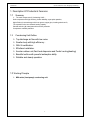
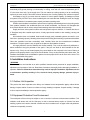
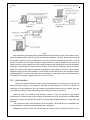
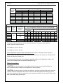
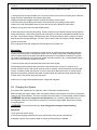
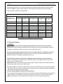
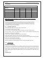
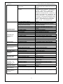
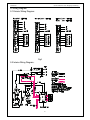
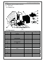
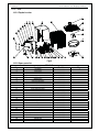
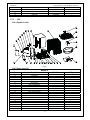
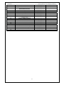
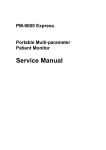
Service Manual
MIH Series
Condensing Units
Heat Pump 1.5 tons to 5 tons
Comfortstar
Service manual for 13seer Heatpump Condensing
Contents
1. Description of Products & Fearures
2. Physical And Electrical Specifications
3. Safety Caution
4. Application
5. Installation Instructions
6. Defrost Cycle
7. Maintenance Instructions
8. Service And Troubleshooting
9. Wiring Diagrams
10.
Explosive Diagram And Spare Parts List
1
Comfortstar
Service manual for 13seer Heatpump Condensing
1. Description Of Products & Fearures
1.1
Summary
The main components of Condensing UnitS :
Sroll compressor with high efficiency, better reliability, super-quiet operation;
High efficiency heat exchanger with inner groove copper pipe, inserting aluminum fin;
The expansion valve can maintain heating capacity.
Painted and zinc-gilt metal parts with corrosion protection
Compressor overload protection
1.2
Condensing Unit Outline
Top discharge air flow with low noise.
Smaller body with high efficiency .
With ULcertification.
Effortless Installation.
Annular outdoor unit,Fast heat dispersion and Powful cooling(heating)
Beautiful outline with powerful antiseptics ability.
Reliable and steady operation.
1.3 Working Principle
MIH series (heat pump) condensing unit
2
Comfortstar
Service manual for 13seer Heatpump Condensing
Filter
Expansion/check
Valve
Expansion /check
Valve
Service Valve
of Liquid Pipe
Axial Flow Fan
Filter
Liquid
separator
Outdoor
Heat
Exchanger
Service Valve
of Gas Pipe
Indoor
Heat Exchanger
Centrifugal Fan
4-Way Valve
Compressor
Cooling
Heating
Fig.1 Working Principle Diagram of Heat Pump Condensing Unit
The working principle diagram of the heat pump Air Conditioner is shown above in fig.1. When the
system operates in cool mode, the low temperature and low pressure refrigerant gas from the heat
exchanger of the indoor unit is sucked by compressor and compressed, the high temperature and high
pressure gas is discharged into heat exchanger of outdoor unit, heating exchanges with air of outside and
turns into the refrigerant liquid, the liquid is throttled by throttling element and changed into the low
temperature and low pressure liquid then flows into the heat exchanger of indoor unit, heating exchange
with the air of the indoor then turns into the low temperature and low pressure refrigerant gas. The above
circle goes round and round. When the system operates in heat mode, the refrigerant flows in the reversible
cycle as the cool mode. The refrigerant gas discharges the heat volume in the indoor heat exchanger,
through the expansion valve and sucks the heating volume from outdoor heat exchanger and forms the heat
pump cycle, this cycle goes round and round, and the demanded high temperature environment is
maintained.
3
20.0
Maximum Overload Amps
41.0
Yes
NA
Internal Overload Protection
Crankcase Heater
1/6
790
120.0
Rated Horse Power (hp)
Nominal RPM
Output Watts
4
ALUMINIUM
Diameter (In)
No. of Blade
Fan Material
Condenser coil
36
18.0
The blade angel
Fan
1.2
RLA (Rated Load Amps)
Fan Motor
10.0
LRA (Locked Rotor Amps)
Model Number
RLA (Rated Load Amps)
SCROLL
ZR16K4-PFV-522
Type / Maker
Compressor
13.7
Minimum Circuit Amps
Voltage - Phase - Frequency (Hz)
208/230 - 1 - 60
694
Airflow Rate (CFM)
Electrical
7.80
1,395
16,300
Sensible heat(Btu/h) (47F)
Total Input Watts (Heating) 16,300
Heating Capacity (Btu/h) (47F)
Heating HSPF
1,535
Total Input Watts (Cooling) 13
3,500
Latent cooling capacity (Btu/h)
SEER
18,000
14,500
Sensible cooling capacity (Btu/h)
MIH18-13
Cooling Capacity (Btu/h)
Performance
Model Number
2. Specifications
Comfortstar
ALUMINIUM
4
18.0
36
120.0
940
1/6
1.0
NA
Yes
56.0
11.4
ZR22K3-PFV-522
SCROLL
25.0
15.3
208/230 - 1 - 60
850
1,793
7.80
21,400
21,400
2,118
13
4,500
19,500
24,000
MIH24-13
1
ALUMINIUM
4
22
29
150.0
830
1/5
1.3
NA
Yes
72.5
15 .0
ZR28K3-PFV-522
SCROLL
35.0
20.0
208/230 - 1 - 60
1,083
2,522
7.80
27,400
27,400
2,584
13
5,500
24,500
30,000
MIH30-13
ALUMINIUM
4
22
29
150.0
830
1/5
1.3
NA
Yes
88.0
17.9
ZR34K3-PFV-522
SCROLL
40.0
23.7
208/230 - 1 - 60
1,210
2,971
7.80
32,000
32,000
3,171
13
7,700
28,300
36,000
MIH36-13
Service manual for 13seer Heatpump Condensing
ALUMINIUM
4
22
29
150.0
830
1/5
1.3
NA
Yes
104.0
20.0
ZR40K3-PFV-522
SCROLL
45.0
26.3
208/230 - 1 - 60
1,448
3,415
7.80
38,500
38,500
3,874
13
11,000
31,000
42,000
MIH42-13
ALUMINIUM
4
22
29
210.0
890
1/4
1.7
NA
Yes
137.0
21.4
ZR47K3-PFV-522
SCROLL
50.0
28.5
208/230 - 1 - 60
1,585
3,862
7.80
43,000
43,000
4,419
13
11,200
36,800
48,000
MIH48-13
ALUMINIUM
3
24
29.5
300.0
1100
1/3
2.1
NA
Yes
148.0
25
ZR54K3-PFV-522
SCROLL
50.0
33.4
208/230 - 1 - 60
1,868
4,747
7.80
52,000
52,000
5,352
13
15,700
43,300
59,000
MIH60-13
24 [610]
24 [610]
Width (Inch/mm)
Depth (Inch/mm)
UL
25.5 (648)
25.5 (648)
216
Depth
Container Loading(40'High)
135
2、Rated in accordance with ARI 210-240 and D.O.E. test standards.
2
30.3(770)
30.3(770)
29.5(750)
UL
ARI
198
183
R-22 /159
Jointing
40
50
50
100
3/4
3/8 28 [710]
28[710]
28.3 [718]
13.1
1/4" Grooved
Enhanced fins
17
0.5 x 0.75
2
135
30.3(770)
30.3(770)
29.5(750)
UL
ARI
203
187
R-22 /159
Jointing
60
100
100
250
3/4
3/8 28 [710]
28[710]
28.3 [718]
13.1
1/4" Grooved
Enhanced fins
17
0.5 x 0.75
2
Service manual for 13seer Heatpump Condensing
Notes:
1、R-22 Charge for the outdoor unit with matching indoor unit and 25' line set;
216
25.2(640)
25.5(648)
25.2(640)
25.5(648)
Width
UL
Height
Shipping
Safety Approvals
ARI
159
146
ARI
148
R-22 / 113
Jointing
40
50
50
100
5/8
3/8 24 [610]
24 [610]
23.8 [604]
8.4
1/4" Grooved
Enhanced fins
17
0.5 x 0.75
2
135
R-22 /113
Performance Certification
Agency Approvals
Ship
Net
Weight (lbs)
Refrigerant Type / Charge (Oz)
Jointing
40
Refrigerant Connection Type
Indoor above Outdoor Unit
Max Vertical Distance (Ft)
50
50
Max Refrigerant Line Length (Ft)
Outdoor above Indoor Unit
5/8
100
Vapor Line Dimension (In)
3/8 Liquid Line Dimension (In)
Refrigerant Line
23.8 [604]
Height (Inch/mm)
Dimensions
8.4
1/4" Grooved
Tube OD and Type
Gross Finned Face Area (Sq Ft)
Enhanced fins
17
0.5 x 0.75
2
Fin Type
Fins per Inch - FPI
Tube spacings (V x H) (In)
Number or Rows
Comfortstar
135
30.3(770)
30.3(770)
29.5(750)
UL
ARI
207
192
R-22 /159
Jointing
60
100
100
250
3/4
3/8 28 [710]
28[710]
28.3 [718]
13.1
1/4" Grooved
Enhanced fins
17
0.5 x 0.75
2
135
30.3(770)
30.3(770)
34.3(870)
UL
ARI
232
216
R-22 / 176
Jointing
60
100
100
250
1-1/8
1/2 28 [710]
28[710]
32.7 [830]
15.3
1/4" Grooved
Enhanced fins
17
0.5 x 0.75
2
90
30.3(770)
30.3(770)
39.4(1000)
UL
ARI
247
221
R-22 / 201
Jointing
60
100
100
250
1-1/8
1/2 29.5[750]
29.5 [750]
32.7 [830]
19.8
1/4" Grooved
Enhanced fins
17
0.5 x 0.75
2
Comfortstar
Service manual for 13seer Heatpump Condensing
3.Warning
Before operating the Air Conditioner, read this manual thoroughly and operate accordingly.
“CAUTION” and “DANGER” have the following meanings with these instructions:
Ć This mark indicates improper operation might lead to serious injury for the users.
CAUTION Ć This mark indicates improper operation might possibly result in personal harm to the
DANGER
user, or damage to property.
DANGER!
Do not use or place combustible and explosive gas or liquid near the air conditioner.
Do not attempt to install Air Conditioner by yourself to guarantee the Air Conditioner can be
permanent use.
In the event of a malfunction (burning smell, etc.), stop operating immediately and turn off the
power switch.
Do not insert fingers or objects into the outlet port or intake grilles.
Do not check or repair the Air Conditioner when it is running.
Do not sprinkle water on the Air Conditioner or operate it with wet hands.
CAUTION
Ć
Before install, ensure the power supply is corresponding to that listed in nameplate and check the
security of the power source.
Before use, ensure the wire connections are proper for avoiding electric shock or fire.
The Air Conditioner should not be operated by children.
Please turn off the power before cleaning the Air Conditioner or replacing the filters.
Turn off power source when not using the Air Conditioner for extended periods.
Do not climb on or place objects on the air conditioner.
POWER SUPPLY
Adequate power supply, adequate cross section of wire. Please consult it with distributor and
professional.
The Air Conditioner must be reliably earthed! The earth wire must be connected to the special
grounding devices. It is forbidden to connect it to water pipe, gas pipe, wires of the lightning rod
and telephone.
The cable must be wired by qualified personnel in accordance with national wiring regulation.
Electricity leakage protection switch and air switch should be fixed in the wire circuit.
4.APPLICATION
Before specifying any air conditioning equipment, a survey of the structure and a heat gain calculation
must be made. A heat gain calculation involves identifying all surfaces and openings that gain heat from the
surrounding air and quantifying that heat gain. It also calculates the extra heat load caused by sunlight and
by humidity removal. These factors must be considered before selecting an air conditioning system to
provide year round comfort. The Air Conditioning Contractors of America (ACCA) J Manual method of load
calculation is one recognized procedure for determining the cooling load. The cooling load calculation
determines the unit size. There are two capacities that enable the equipment to provide comfort. The first is
sensible capacity. How much sensible heat can the unit remove? Sensible heat is the heat energy measured
on the dry bulb thermometer.
The second form of heat is called latent or hidden heat. This is heat held in the humidity in the air.
1
Comfortstar
Service manual for 13seer Heatpump Condensing
Removing this heat does not affect a thermometer. However, removing the heat held in the moisture in the
air greatly increase comfort. A properly sized unit removes both forms of heat, producing a comfortable living
space. An oversized system cycles on and off too quickly and does not properly remove humidify ,
producing an uncomfortable living space. Select the indoor and outdoor equipment combination based on
the manufacturer’s engineering data. After the proper equipment combination has been selected, satisfying
both sensible and latent conditioning requirements, the system must be properly installed. Only then can the
unit provide the comfort the manufacturer built into it.
There are several factors that installers must consider.
? Outdoor unit location
? Proper equipment evacuation
? Outdoor unit refrigerant charge
? Indoor unit air flow
? Indoor unit blower speed
? Supply and return air duct design and sizing
? System air balancing
? Diffuser and return air grille location and sizing
Working Temperature
Indoor unit
Outdoor
Max cooling function
86
Min cooling function
61
Max heating function
Min heating function
86
61
115
55 (Low ambient control kit should be installed when temperature lower
than 55
75
20(Auxiliary heater shoud be installed when below 20)
Unit Dimensions
ğ
Table1
inch
Model
18&24
30&42
48
60
length
24
28
28
29.5
Height
23.8
28.3
32.7
32.7
Table 2
Note:
1.The piston placed in the indoor unit is used when cooling.
2. Expansion Valve placed in the outdoor unit is used for indoor unit when heating.
The air distribution system has the greatest effect. The duct system is totally in the control of the
contractor. The industry can only recommend the correct procedure.
The correct air quantity is critical on air conditioning system. Proper operation, efficiency, compressor
life and humidity control depend on the correct balance between indoor load and outdoor unit capacity. High
indoor air flow increases the possibility of high humidity problems in cooling. Low indoor air flow reduces
total capacity, and causes coil icing. Serious harm can be done to the compressor in either condition.
Air conditioning requires a specified air flow. Each ton of air conditioning requires 400 cubic feet of air
per minute (400CFM/TON).
2
Comfortstar
Service manual for 13seer Heatpump Condensing
Duct design and construction should be carefully done. System performance can be lowered
dramatically through bad planning or workmanship. In cooling ,a hot attic can cause a temperature gain of
3°in the return duct and 4°in the supply duct. This can reduce the cooling capacity of an air conditioning
system by as much as 30%.This means a loss of almost one ton of cooling capacity from a three ton system.
Air leakage of only 3% in a return duct can cause a 5% loss in system capacity. 3% leakage on a three
ton system is only 30 CFM. Two or three unsealed joints can cause this leak. Sealing the return and supply
ducts pays dividends in increased system capacity and lower operating costs.
Effective duct insulation is essential to prevent loss of capacity and sweating ducts in the cooling mode.
Duct systems installed in the conditioned space can be left uninsulated , but a dense 1/2” fiberglass duct
liner reduces blower and air noises, and prevents sweating ducts when humidity levels are high.
Supply and return duct systems in attics and crawl spaces require a minimum 1” of dense duct liner or
2” fiberglass wrap with a sealed vapor barrier. A leaky vapor barrier results in duct sweating, causing wet
insulation.
Wet insulation does not insulated .Heat transfer through poorly insulated systems can result in over
50% loss in operating capacity. Sweating ducts also promote rusting ducts resulting in premature duct failure.
Other duct materials have been successfully used. Carefully follow the duct manufacturers’ installation
instructions. The duct system is only as good as the planners and installers construct.
Air supply diffusers must be selected and located carefully. They must be sized and positioned to
deliver treated air along the perimeter of the space. If they are too small for their intended air flow the
become noisy. If they are not located properly they cause drafts on the occupants in the rooms. Return air
grilles must be properly sized to carry air back to the blower. If they are too small they also cause noise. The
installers should balance the air distribution system to ensure proper air flow to all rooms in the home. This
ensures a comfortable living space.
5. Installation Instructions
! WARNING
These instructions are intended as an aid to qualified, licensed service personnel for proper installation,
adjustment and operation of this unit. Read these instructions thoroughly before attempting installation or
operation. Failure to follow these instructions may result in improper installation, adjustment, service
or maintenance possibly resulting in fire, electrical shock, property damage, personal injury or
death.
5.1 Outdoor Unit Inspection
This product has been inspected at the factory and released to the transportation agency without known
damage. Inspect exterior of carton for evidence of rough handling in shipment. Unpack carefully. If damage
is found, report immediately to the transportation agency.
5.2 Equipment Protection From Environment
The metal parts of the unit may be subject to rust or corrosion in adverse environmental conditions. This
oxidation could shorten the unit life. Salt spray or mist in seacoast areas, sulphur or chlorine from lawn
watering systems and various chemical contaminants from industries such as paper mills and petroleum
refineries are especially corrosive.
3
Comfortstar
Service manual for 13seer Heatpump Condensing
If the unit is to be installed in an area where contaminants are likely to be a problem, special attention should
be given to the equipment location and exposure.
Avoid having lawn sprinkler heads spray directly on the unit cabinet.
In coastal areas, locate the unit on the side of the building away from the waterfront.
Shielding provided by fence or shrubs may give some protection.
Regular maintenance will reduce the buildup of contaminants and help to protect the unit's finish.
! WARNING -Disconnect all electrical power to the unit before servicing. Disconnect power to both the
indoor and outdoor units. NOTE: There may be more than one electrical disconnect switch. Failure to
shut off power can cause electrical shock resulting in personal injury or death.
Frequent washing of the cabinet, fan blade and coil with fresh water.
Regular cleaning and waxing of the cabinet with good automobile polish.
A good liquid cleaner may be used several times a year to remove matter that will not wash off with water.
The best protection is frequent cleaning, maintenance and minimal exposure to contaminants.
5.3 Installation
The Position of Installation
The Air Conditioner shall be installed in accordance with national and local
wiring regulation. Quality of installation can affect its operation. It is forbidden to fix
the unit by users themselves, please contact dealer for repair. It must be fixed and
adjusted by the qualified person. Switch on after all the fixing work had been
finished.
Outdoor Unit must be fixed on stable and solid surface of floor.
Don’t install Outdoor Unit under window or between buildings, and prevent the operation noise from
entering into room.
There should be no obstructions at both air intake and outlet vents for indoor and outdoor units for
maintaining well air ventilation.
When installing indoor unit, make sure that the hanging parts at top are strong enough to stand the
weight of unit.
Do not install the Air Conditioner in place with flammable and explosive things, or in some dusty place.
Make sure to lessen the length of connecting pipe between the indoor and outdoor unit, and the number
of bends.
Don’t connect duct to inlet/outlet of outdoor unit. When indoor unit in heating
mode, condensing water will drop from the chassis of outdoor unit. The
condensing water will freeze when the outdoor temp below 0
32
.
¥č ⚻Ď
The Installation Position of Outdoor Unit
Ensure the place where is well ventilated and there is sufficient space for maintenance.
It’s shown as follow:
4
Comfortstar
Service manual for 13seer Heatpump Condensing
Floor
mm
Floor
Fig.3. Installation Position of Outdoor Unit
When removing the outdoor unit, two ropes are needed to hang the unit along the four
directions. In order to avoid the excursion, the angle between the ropes should be less than
40o. It is shown as follow:
Below
40° 40o
危险
DANGER
Fig.4. Condensing Unit Hoisting Sketch
5.4 Refrigerant Piping
The refrigerant piping is very important as it’ the base of the natural operation and high efficiency of the air
conditioning system.
5
Comfortstar
Service manual for 13seer Heatpump Condensing
Fig5
Only refrigeration-grade copper piping (dehydrated and sealed) should be used. Take extreme care to
keep the refrigerant tubing clean and dry prior to and during installation. If in doubt, blow out the tubing with
dry nitrogen to remove any chips or debris before connection. Always keep tubing sealed until it is in place
and the connections are to be made. Refrigerant piping should be as short as possible, with a minimum of
elbows or bends, to avoid capacity loss and increased operating costs. Refrigerant lines must be adequately
supported. If metal strapping is used to secure the tubing, do not allow the strapping to directly contact the
tubing. Use a closed cell insulation to separate the strapping from the tubing. Do not kink or twist the tubing.
Refrigerant piping should not be installed in a cement slab, as this limits access to the refrigerant should a
leak be suspected. To ensure good oil return to the compressor, it is important to pitch the horizontal suction
line toward the compressor, approximately 1/2" for every 10' of line.
5.5 Line Insulation
Suction line requires insulation in order to prevent condensation from forming on the piping and to
prevent heat gain caused by surrounding air. Generally 3/8" wall thickness of Arm flex or equivalent is
satisfactory. In severe application (hot, high humidity areas) greater thickness may be required. Apply the
line insulation by sliding it on the sealed tubing before cutting and making connections.
Liquid line does not necessarily need insulation, however, if they are exposed to high ambient
temperatures (i.e. kitchen, boiler rooms, hot attics & rooftop surface), then, they should be insulated. Make
sure to use the proper size tubing for the liquid line to prevent liquid refrigerant flashing to a vapor within the
liquid line.
Do not allow the vapor line and liquid line to touch together. This would cause an undesirable heat
transfer resulting in capacity loss and increased power consumption.
Refrigerant Line Sizing Check the following table for correct suction and liquid line sizes for any
6
Comfortstar
Service manual for 13seer Heatpump Condensing
combination of the unit size and the maximum refrigerant line length. Refrigerant Line Sizing
Unit Size
(Ton)
1.5
2.0
2.5
3.0
3.5
4.0
5.0
0 – 50
Suction
5/8
5/8
3/4
3/4
7/8
1-1/8
1-1/8
Liquid
3/8
3/8
3/8
3/8
3/8
1/2
1/2
Refrigerant Line Length (Ft)
50 – 100
Line Outside Diameter (In)
Suction
Liquid
7/8
3/8
7/8
3/8
7/8
3/8
3/4
3/8
1-1/8
3/8
1-1/8
1/2
1-1/8
1/2
Table 3
100 – 250
Suction
/
/
/
7/8
1-1/8
1-1/8
1-1/8
Liquid
/
/
/
3/8
3/8
1/2
1/2
R-22 Cooling Capacity Loss For Various Line Lengths &Tube Diameters
Cooling Capacity loss(%) at Total Equivalent Line Length(ft.) Refer to
Acceptable
Model
Liquid
Long Line Application Guideline to calculate equivalentlength
Vapor Line
Size
line(in.)
Standard
Size(in.)
Long line Application (Requires Accessories)*
Application
25'
50'
80' 81' 100' 125' 150' 175' 200' 225' 250'
18
0
1
1
1
1
/
/
/
/
/
/
5/8
24
0
1
1
1
2
/
/
/
/
/
/
3/8
30
0
1
1
1
1
/
/
/
/
/
/
3/4
36
1
2
3
3
4
5
5
6
7
8
9
42
1
2
4
4
5
6
7
8
10
11
12
48
7/8
1
2
2
2
3
4
5
5
6
7
8
1/2
60
1-1/8
1
2
3
3
5
6
7
8
9
10
11
Table 4
The factory charge is sufficient for 25 feet of standard liquid line. For longer or shorter liquid line
lengths, adjust the charge as follows:
3/8" Liquid line +/- 0.6 oz. Per foot
1/2" Liquid line +/- 0.8 oz. Per foot.
Vertical Separation between Indoor and Outdoor Units Maximum allowable vertical separations
between indoor and outdoor units are 100' when the indoor unit is below the outdoor unit , and 60' when the
indoor unit is above the outdoor unit.
To ensure good oil return to the compressor when the indoor unit is below the outdoor unit,
suction line oil trap should be used as illustrated in Fig. 5.
Tubing Connections
! CAUTION - Use extreme caution in removing the caps from the suction and liquid line fittings, as
there is pressure present. A fitting is on the liquid line to remove pressure.
! CAUTION - Condensing units are charged with refrigerant. Condensing unit liquid and suction valves are
closed to contain the charge within the unit. Do not force the valve stem against the retaining ring. If the
valve stem is backed out past the retaining ring, system pressure could force the valve stem out of the valve
body and possibly cause personal injury.
7
Comfortstar
Service manual for 13seer Heatpump Condensing
Instructions on the field tubing connections and valve opening procedure are as follow:
1.Tubing should be cut square. Make sure it is round and free of burrs at the connecting ends. Clean the
tubing to prevent contamination from entering the system.
2.Make sure that both refrigerant shutoff valves at the outdoor unit are closed.
3.Push the tubing into the fitting until it stops. This prevents flux from getting into the system.
4.Remove the cap and Schrader valve core from the service port to protect the valve seals.
5.Wrap a wet rag around the valve stub before brazing.
6. Braze the joints of interconnecting tubing. Flow dry nitrogen into the shutoff valve port and through the
tubing while brazing. 7.After brazing quench with a wet rag to cool the joint. Reinstall the Schrader core in
the valve, if removed for brazing. 8.Pressurize the lines to 150 psi maximum with dry nitrogen. Check for
leaks at all joints with liquid detergent. If a leak is found, repair it after removing the nitrogen. Repeat the
process and re-check.
9.Do not purge the lines with refrigerant. Evacuate the lines and indoor coil.
Evacuation
All new installations must be evacuated to a deep vacuum in order that all noncondensible gases and
moisture are removed prior to charging the system. Air in a system causes high condensing pressure,
which increases power consumption and reduces performance. The presence of moisture in a system
can render it inoperable in a very short time. Proper evacuation assures a dry, uncontaminated system.
Here is the recommended evacuation procedure:
1.Connect vacuum pump to both liquid and suction valve service ports.
2.Evacuate the interconnecting tubing and indoor coil to 500 microns or less for a minimum of 30
minutes. Close the valve to the vacuum pump and wait 15 minutes. Vacuum should not rise above 800
microns. If unable to obtain 500 microns, or vacuum rises above 800 microns over 15 minutes period,
discontinue evacuation, pressurize and check for leaks. Repair any leaks found and repeat the step 2.
3.Close valve to the vacuum pump and stop pump.
4.When sure of a tight, well evacuated system, charge with refrigerant.
5.6 Charging the System
(For systems with capillary tube or expansion valve or fixed orifice metering device)
Before checking the system charge, make sure that the outdoor unit and indoor coil must be an approved
match per the unit specification. The indoor conditions should be within 2 F of the desired comfort conditions.
! WARNING -Do not vent refrigerant to the atmosphere! It is a violation of federal law to do so. If
the refrigerant needs to be removed from a system to correct the charge inside, always use a recovery
or recycling device.
! WARNING -To prevent personal injury, wear safety glasses and gloves when handling
Refrigerant.
1.Fully open both shutoff valves.
2.Connect service gage manifold to the valve service ports, being sure to evacuate lines.
3.Startup the system. Run system at least 10 minutes to allow pressure to stabilize.
8
Comfortstar
Service manual for 13seer Heatpump Condensing
4.Temporarily install thermometer on suction (large) line near condensing unit. Be sure of good contact
between thermometer and line. Wrap thermometer with insulating material to assure accurate reading.
5.Refer to Table 5 for proper system superheat. Add charge to lower superheat. Remove charge to
raise superheat. Carefully remove gage lines.
System Superheat
Ambient
Temperature At
Condenser Inlet
()℉
Return Air Temperature ( )℉
65
70
75
80
85
60
17
25
30
33
37
65
13
19
26
32
35
70
5
14
20
28
32
75
5
10
17
25
29
80
5
12
21
26
85
5
10
17
20
90
7
12
18
95
5
5
5
5
5
100
Table5 :System charging table by superheat
5.7 Electrical Wiring
! WARNING
A means of strain relief must be installed to this appliance at the electrical service entrance.
Make sure that interconnecting wires between indoor and outdoor units meet the standards, codes and
regulations. Incomplete connection or fixing of the wire could result in a fire.
Do not use intermediate connection of the power cord or the extension cord and do not connect
many devices to one AC outlet. It could cause a fire or an electric shock due to defective contact,
defective insulation, exceeding the permissible current, etc.
Perform electrical work according to the installation manual and be sure to use an exclusive
circuit. If the capacity of the power circuit is insufficient or there is incomplete electrical work, it could
result in a fire or an electric shock.
Ground the unit. Do not connect the ground to a gas pipe, water pipe, lighting rod or telephone ground.
Defective grounding could cause an electric shock.
Electrical installation will consists of power supply wiring to the condensing unit and control wiring between
thermostat, indoor unit and the condensing unit. All wiring must be in accordance with National Electrical
Code and/or local ordinances that may apply.
(See unit wiring diagram furnished with this instruction).
The condensing unit rating plate and the tables of "Physical and Electrical Specifications /provide pertinent
data necessary for the selection of proper size electrical service and over-current protection devices.
Table 6 provides data on the minimum copper wire size as a function of supply wire length and
9
Comfortstar
Service manual for 13seer Heatpump Condensing
circuit ampacity.
Copper Wire Size - AWG (1% Voltage Drop)
Supply Circuit
Ampacity
Supply Wire Length - Ft
100
150
10
8
15
50
14
200
6
20
12
8
6
4
25
30
35
40
45
10
10
8
8
6
8
8
6
6
4
6
4
4
4
3
4
4
3
2
2
50
6+
4
3
1
Table6: Minimum Wire Size Based on N.E.C. for 60 C Type Copper Conductors
Below 100 Ampacity.
The owner should be made familiar with the location of the over-current protection, the proper
size for this application and the proper procedure for disconnecting power service to the unit.
The condensing unit control wiring requires a 24 Volt minimum, 25 VA service from the indoor
transformer as shown on the wiring diagram.
5.9
SYSTEM STARTUP
1.Turn thermostat to "OFF", turn on power supply at connect switch.
2.Turn temperature setting as high as it will go.
3.Turn fan switch to "ON". Indoor blower should run. Be sure it is running in the right direction.
4.Turn fan switch to "AUTO". Turn system switch to "COOL" and turn temperature setting below room
temperature. Unit should run in cooling mode.
5.Check to see if compressor and outdoor fan are running correctly?.
6.Check the refrigerant charge (see Instructions under "Charging the System").
7.Replace service port caps. Service port cores are for system access only and will leak if not tightly capped.
8.Check unit for tubing and sheet metal rattles.
9.Instruct the owner on operation and maintenance.
Leave this "Installation and Operating Manual" and the "Use and Care Manual" with owner.
5.10 OPERATION
SEQUENCE OF OPERATION
In order to service and troubleshoot an air conditioning system a service technician must understand the
unit’s sequence of operation. this is the order of events the system undergoes to cycle itself on and off.
Knowing how the units operate properly aids in determining where to start troubleshooting when the unit
doesn’t operate properly .Where the system varies from its normal sequence is a major clue to any
problems.
COOLING CYCLE
10
Comfortstar
Service manual for 13seer Heatpump Condensing
Mechanical . the operation sequence as follows:
1.
The compressor pumps out high pressure ,superheated refrigerant vapor.
2.
The vapor leaves the compressor and passes through the reversing valve.
3.
It flows through the outdoor vapor line to the finned outdoor coil. Air from the outdoor fan removes heat
from the refrigerant vapor .When enough heat is removed ,the vapor condenses into a high pressure
liquid .The liquid temperature is slightly warmer than ambient air temperature.
4.
This warm ,high pressure liquid leaves the outdoor coil ,and flows through the small copper
5.
At the end of the liquid line the refrigerant passes through the a flowcheck device ,reducing a pressure
and temperature .
6.
As the cool liquid ,under reduced pressure ,enters the indoor coil surface it expands and absorbs heat
from the indoor air passing over the finned surface ..Heat from the indoor air ,causes the low pressure liquid
to evaporate and cools the indoor air. The refrigerant is now a cool vapor.
7.
The cool refrigerant vapor travels through the larger ,insulated vapor line to the accumulator .
8.
The accumulator separator separates any liquid refrigerant and holds it. Only vapor refrigerant and
refrigerant oil leave the accumulator .The oil is drawn out through a special port inside the accumulator.
9.
Refrigerant vapor flows through the suction line to the intake of the compressor .The cycle then repeats.
Electrical . The operation cycle as follows:
1.
The thermostat calls for cooling
2.
This sends a 24 voltage signal through the “Y” terminal to the compressor start kit ,after 3 minutes the
compressor contactor in the outdoor unit are closed .The compressor and outdoor fan start.
3.
At the same time ,a 24 Voltage signal flows through the “G” Terminal to the indoor blower relay.. The
indoor blower starts.
4.
the cooling system is now in operation.
5.
The thermostat satisfies and ends the call for cooling.
6.
This ends the 24 Voltage signal to the compressor start kit and the outdoor unit stops.
7.
This ends the 24 voltage signal to the indoor blower relay and this indoor blower strips
8.
The system is now off.
6. Defrost Cycle
During heat pump mode, If the compressor continually running for 44 minutes and the outdoor coil
temperature drop below 23 oF for more than 1 minute, the defrost cycle start: outdoor fan stop, reversing
valve energized, meanwhile the indoor auxiliary heater come on. The maximum time for defrost cycle is 10
minutes. When defrost cycle is terminated, the outdoor fan come back on, reversing valve de-energized and
the indoor auxiliary heater turn off.
When switch system from heat pump mode to cooling mode, the defrost cycle will be terminated
immediately.
Outdoor defrost control board display:
Both LED1 and LED2 will blink when units working under normal condition, during defrost cycle, both
LED1 and LED2 will be continually on.
11
Comfortstar
Service manual for 13seer Heatpump Condensing
7. Maintenance Instructions
Ć Make sure to turn off the power before maintenance.
Warning
The heat exchanger of Outdoor unit must be cleaned regularly. At least clean it for once every two
months, you can clean the dust and sundries on its surface with vacuum and nylon brush, or blow
them by using compressing air.
Check connecting pipe and connector, if there is oil leakage, repair it in time.
It is forbidden to wash the unit by water, or it may cause electric shock.
Inspection at the beginning of the using:
1) Remove any block near the outdoor;
2) Proper grounding;
3) Proper circuitry;
Maintenance after the using season:
4) Clean the body of the outdoor;
5) Proper protection of the outdoor;
6) Turn off the power supply.
Notice
When testing the piping system,do not mix the Oxygen and Acetylene into the piping system.
Pls use Nitrogen or Refrigeration to keep the testing safe.
8. Service And Troubleshooting
8.1. Fill more oil into Compressor
Processing:
1) Collecting the refrigeration under cooling model,fasten up the big and small vavles;
2) Disconnecting the bigger copper pipe and valve with welding torch;
3) Filling the oil to the copper pipe;
4) Welding the copper pipe together with the vavle;
5) Vacuumizing then keep pressure for 30 minutes;
6) Open the two valves;
7) Turn on the unit.
8.2 Compressor replacement:
Processing:
1) Switching off the power supply of the outdoor unit,make marks for each wires when removing the
power cord of the compressor,;
2) Loosening the bolts of the compressor;
3) Disengage the Discharge pipe from the vent of the Compressor;
4) Disengage the suction pipe from the inspiratory end of the compressor;
5) Put the new compressor on the right place,pull out all of the rubber plugs,and connect the pipes
after that,first the discharge pipe then the suction pipe.Pls do weld the pipes immediately after you
12
Comfortstar
Service manual for 13seer Heatpump Condensing
pull out the rubber plugs or else the water vapor may enter into the compressor. When welding the
pipes pls be with Nitrogen and the pressure of the Nitrogen is 1.0~3.0kgf/cm2。
6) Resume the system as the condition before the compressor replacement;
★When connect the power cord of the compressor,turn it on once to test whether it rolls back.(If
rollback,there will be depressing sound from it.)
★If there is any leakage of the lubricating oil,pls fill more.
Notice:Usually the discharge pipe is thin and there is at least one U bend in the pipe,so we disengage
this pipe first when replace the compressor.
8.3 Maintenance when Refrigeration leakage:
Best hermetic system is the base of the reliable function.When there is leakage,turn off the system
immediately and make leak hunting.
Processing:
1) Charge Nitrogen 20.0kgf/cm2 into the system;
2) Check the joint of the pipes with suds,mark the leaking point;
3) When all of the checking finished,charge more Nitrogen (1.0~3.0kgf/cm2) then welding the leaking
point;
4) After the welding,charge high-pressure Nitrogen(25.0kgf/cm2); and check the Press after 48
hours,calculate the Press Decline with the Formula below,the result should be less than 1% of
Testing Press;If not,pls recheck the system to find out the leakage joint.
?P=P1-P 2(273+T 1)/(273+T 2)
In the formula:? P——the Press Decline(MPa).
P1,P2——Press of Nitrogen at the beginning and the finishing(MPa).
T 1,T2——Tempreture of the Nitrogen at the beginning and the finishing(℃).
If possible,test the leakage with Halogen Testing Instrument at the beginning of the leakage.
8.4 Vacuumizing for the pipeline after maintenance:
Vacuum pipeline can keep the system running naturally and high efficiently.So vacuumizing after leak
hunting is necessary.
Processing:
1) Discharge the Nitrogen first;
2) Connect the pressure gauge to the service vavle,you can get the result of the vacuum from the
lower-pressure gauge;
3) Turn on the vacuum pump;
4) When the vacuum reaching-1.0kgf/cm2,continue 0.5~1.0 hour then turn the pump off;
5) Connect the tube to the Refrigeration Pot, after discharging the air in the tube, charge Refrigeration
into the system until the pressure reach 0.0kgf/cm2;
6) Change the tube to connect to the vacuum pump again,turn on the pump to vacuumizing 30
minutes until the vacuum reach -1.0kgf/cm2.
13
Comfortstar
Service manual for 13seer Heatpump Condensing
8.5 Checking before Operation:
No.
1
2
3
4
5
6
7
8
9
10
12
13
14
15
16
17
18
19
20
21
22
23
Items
Capacity between outdoor and indoor should match
Connecting pipes connected properly
Correct dimension and position of the air outlet.
Proper duct design for indoor unit
Correct position of indoor unit
Specs and gradient of the drainpipe are right
Make sure the chassis of indoor clean
Eligible pipe for condensing water
Proper copper pipe and thermal insulation pipe
Clean the impurity after welding
Correct fixing position of outdoor
Proper shock absorption of outdoor
Vacuumizing for both liquid pipe and gas pipe
Enough time for Vacuumizing
Whether the pressure coming back after 1 hour
holding
Whether need more refrigeration
Whether the outdoor vavles opened
Proper power supply
Terminal connected substantially
Make sure the switch for leaking current installed
Proper length of the power cable
Reliable grounding
? yes
? yes
? yes
? yes
? yes
? yes
? yes
? yes
? yes
? yes
? yes
? yes
? yes
? yes
? yes
?
?
?
?
?
?
?
?
?
?
?
?
?
?
?
Remark
no
other
no
other
no
other
no
other
no
other
no
other
no
other
no
other
no
other
no
other
no
other
no
other
no
other
no
other
no
other
? yes
? yes
? yes
? yes
? yes
? yes
? yes
?
?
?
?
?
?
?
no
no
no
no
no
no
no
other
other
other
other
other
other
other
8.6 Troubleshooting
! WARNING – Disconnect all electrical power to the unit before servicing. Disconnect power to both the
indoor and outdoor units. NOTE: There may be more than one electrical disconnect switch. Failure to shut
off power can cause electrical shock resulting in personal injury or death.
Symptom
No cooling/heating
Insufficient Cooling
Possible Cause
Remedy
Power off or loose electrical
connection
Incorrect thermostat setting
Make sure main switch is ON. Check and
tighten all connections.
Set thermostat correctly
defective 4-way valve
compressor without pump function
check the valve coil or replace it
replace it
Dirty filters
Indoor air blockage
Clean & replace
Check supply registers and return grills for
blockage.
Clear away leaves and other debris
Recalculate load
Check – should be 400CFM/Ton
Charge correctly per instruction.
Recover refrigerant, evacuate & recharge, add filter
drier
At compressor terminals, voltage must be
within 10% of rating plate volts when unit is
Blocked outdoor coil
Improperly sized unit
Improper airflow
Incorrect refrigerant charge
Air, non-condensable or moisture in system
Incorrect voltage
running.
Water on floor or in
furnace
Condenser fan and
compressor don’t run
Blocked condensate drain and “P” trap
Remove blockage
AC Contact not connect to the power
supply wire or not tightly fasten.
The outdoor power supply main circuit
Re-connect the power supply wire ,and tightly
fasten.
Dial the power supply switch to “ON ”
14
Comfortstar
switch locate “OFF” position or fuse failure
of main circuit
The control coil of AC Contactor no 24 V
AC power
Run or start capacitor defective
Loose connection
Compressor stuck, grounded or open motor
winding, open internal overload
Low voltage condition
Condenser fan runs,
compressor doesn’t
compressor runs,
Condenser fan
doesn’t
Service manual for 13seer Heatpump Condensing
position or change the fuse and make sure the
main touch point of AC Contactor have current go
through
Check if the relay P2 of 3-minute timer board have
current output ,if not ,check if P1、 P3 have 24 V
AC input , if have 24V AC , please check if it
keep for 3 minutes , if so and P2 no output ,
change the 3-minute timer board; if keep time < 3
minutes ,P2 no output ; if P1 、P3 no24V AC,first
check the thermostat C 、Y terminal have 24 V AC,
if no 24 V AC,then check the thermostat or reset
the setting temp.; if have 24 V AC ,check if the C Y
and P1 、 P3 connection wire cut off or fasten
loosely,if cut off ,then change the parts.
Replace
Check and tighten all connections.
Wait for 2 hours for overload to reset. Replace
compressor if still open.
At compressor terminals, voltage must be
within 10% of rating plate volts when unit is
running.
Low voltage condition
Run capacitor defective
Loose connection
Fan stuck, grounded or open motor
winding, open internal overload
Low voltage condition
Add start kit components
Replace
Check and tighten all connections.
Wait for 2 hours for overload to reset.
Replace Fan if still open.
At compressor terminals, voltage must be
within 10% of rating plate volts when unit is
running.
Register sweat
High head – Low
vapor pressures
High head – High or
normal vapor
pressures
Low head – High
vapor pressures
Low vapor – cool
compressor – iced
evaporator coil
High vapor pressure
Fluctuating head and
vapor pressures
Pulsing noise at
metering device or
liquid line
Defective overload protector
Refrigerant undercharge
Low evaporator airflow
Replace – check for correct voltage
Add refrigerant
Increase blower speed or reduce restriction
– replace air filter
Restriction in liquid line, metering
Replace defective components
device or filter drier
Flowrator piston size too small
Incorrect capillary tubes
Blocked outdoor coil
Refrigerant overcharge
Condenser fan not running
Air, non-condensibles or moisture in system
Excessive load
Defective compressor
Air or non-condensibles in system
Change to correct size piston
Change coil assembly
Clear away leaves and other debris
Correct system charge
Repair or replace
Recover refrigerant, evacuate & recharge, add filter
drier
Change to correct size piston
Replace compressor
Replace coil assembly
Increase blower speed or reduce restriction –
replace air filter
Add low ambient kit
Recover refrigerant, evacuate & recharge,
add filter drier
Recheck load calculation
Replace
Recover refrigerant, evacuate & recharge.
Air or non-condensibles in system
Recover refrigerant, evacuate & recharge
Flowcheck piston size too large
Defective compressor valves
Incorrect capillary tubes
Low evaporator airflow
Operating below 65 ° F outdoors
Moisture in the system
15
Comfortstar
Service manual for 13seer Heatpump Condensing
9. Wiring Diagram
9.1 Exterior Wiring Diagram:
Fig6
9.2 Interior Wiring Diagram:
16
Comfortstar
Service manual for 13seer Heatpump Condensing
10. Explosive view And Spare Parts List
10.1 18K & 24K
10.1.1 Exposive view
Fig8
10.1.2 Spare parts list
MIH18-13
No.
discription
Part No.
Qty.
1
2
3
4
5
6
7
8
9
10
11
12
13
14
15
16
Nut M5X7
Cover Plate
Fan Motor SW120C
Ripple Pipe
Fixed Block
AxialFlowFan
Gas-liquid Separator
Compressor
Base Plate Sub-Assy
4-way Valve
4-way Valve Accessary
Filter
Bidirection Strainer
Tube Clip
Cut-off Valve 5/8
Cut-off Valve 3/8
Thermal Expansion Valve BAE1-1/2HCA ODF
3/8X1/2
One-way Valve
Cabinet
Tube-exit plate
Temperature Sensor
Electric box cover
Capacitor CBB61/CBB611A 6uF/500V
AC Contactor CJX9B-25S/D-C1
Terminal Board
70318204
01258248
15702101
05012140
01722121
10358203
07228217
00202201
012021091
430004033
43008214
07215201
03410107
021400055
07138234
07138232
07332206
4
1
1
1
1
1
1
1
1
1
1
1
1
1
1
1
1
07138202
01318206
01388210
3900012125
01418231
33010037
44010250
42011242
1
1
1
1
1
1
1
1
17
18
19
20
21
22
23
24
25
17
Comfortstar
26
27
28
29
30
31
32
Service manual for 13seer Heatpump Condensing
Main Board
Capacitor Clamp
Capacitor CBB65 30uF/450V(440V)
Connection Sheet Sub-Assy
Condenser Sub-Assy
Current Divider
Side Plate
30221401
02143401
33000018
013882141
01152215
07224041
01308226
1
1
1
1
1
1
1
MIH24-13
No.
discription
Part No.
Qty.
1
2
3
4
5
6
7
8
9
10
11
12
13
14
15
16
Nut M5X7
Cover Plate
Fan Motor SW120B
Ripple Pipe
Fixed Block
AxialFlowFan
Gas-liquid Separator
Compressor
Base Plate Sub-Assy
4-way Valve
4-way Valve Accessary
Filter
Bidirection Strainer
Tube Clip
Cut-off Valve 5/8
Cut-off Valve 3/8
Thermal Expansion Valve BAE2HCA ODF
3/8X1/2
One-way Valve
Cabinet
Tube-exit plate
Temperature Sensor
Electric box cover
Capacitor CBB61 5uF/450V (TUV/VDE)
AC Contactor CJX9B-25S/D-C1
Terminal Board
Main Board
Capacitor Clamp
Capacitor CBB65 45uF/440V(450V)
Connection Sheet Sub-Assy
Condenser Sub-Assy
Current Divider
Side Plate
70318204
01258248
15018254
05012140
01722121
10358203
07228217
00202202
012021091
43000404
43008214
07215201
03410107
021400055
07138234
07138232
07332207
4
1
1
1
1
1
1
1
1
1
1
1
1
1
1
1
1
07138202
01318206
01388210
3900012125
01418231
33010064
44010250
42011242
30221401
02143401
33000012
013882141
01152215
07224041
01308226
1
1
1
1
1
1
1
1
1
1
1
1
1
1
1
17
18
19
20
21
22
23
24
25
26
27
28
29
30
31
32
18
Comfortstar
Service manual for 13seer Heatpump Condensing
10.2 30K & 36K
10.2.1 Explosive view
Fig9
10.2.2 Spare parts list
MIH30-13
No.
discription
Part No.
Qty.
1
Nut M5X7
2
3
Cover Plate
Fan Motor SW150D
4
5
6
7
8
9
10
11
12
13
14
15
16
Ripple Pipe
Fixed Block
AxialFlowFan
Gas-liquid Separator
Compressor
Base Plate Sub-Assy
4-way Valve
4-way Valve Accessary
Filter
Bidirection Strainer
Tube Clip
Cut-off Valve 3/4
Cut-off Valve 3/8
Thermal Expansion Valve TDEX3 ODF
f 10X16
One-way Valve
Cabinet
Tube-exit plate
Temperature Sensor
Electric box cover
Capacitor CBB61/CBB611A 6uF/500V
70318204
01258210
15702102
05278205
10378211
10358211
07228217
00100106
0120822001
43000405
43008214
07210037
03410107
021400055
07138233
07138232
07332204
4
1
1
1
1
1
1
1
1
1
1
1
1
1
1
1
1
07138202
01318206
01388210
3900012125
01418231
33010037
44010250
42011242
30221401
1
1
1
1
1
1
1
1
1
17
18
19
20
21
22
23
24
25
26
AC Contactor CJX9B-25S/D-C1
Terminal Board
Main Board
19
Comfortstar
27
28
29
30
31
32
33
Service manual for 13seer Heatpump Condensing
Capacitor Clamp
Capacitor CBB65 45uF/440V(450V)
Connection Sheet Sub-Assy
Condenser Sub-Assy
Current Divider
Current Divider
Side Plate
02143401
33000012
01388222
0115210301
07224130
06642036
01318213
1
1
1
1
1
1
1
MIH36-13
No.
discription
Part No.
Qty.
1
Nut M5X7
2
3
4
5
6
7
8
9
10
11
12
13
14
15
16
17
18
19
20
21
22
23
24
25
26
27
28
29
30
31
32
33
Cover Plate
Fan Motor SW150D
Ripple Pipe
Fixed Block
AxialFlowFan
Gas-liquid Separator
Compressor
Base Plate Sub-Assy
4-way Valve
4-way Valve Accessary
Filter
Bidirection Strainer
Tube Clip
Cut-off Valve 3/4
Cut-off Valve 3/8
Thermal Expansion Valve
One-way Valve
Cabinet
Tube-exit plate
Temperature Sensor
Electric box cover
Capacitor CBB61/CBB611A 6uF/500V
70318204
01258210
15702102
05278205
10378211
10358211
07228217
00202203
0120822001
43000405
43008214
07210037
03410107
021400055
07138233
07138232
07138203
07138202
01318206
01388210
3900012125
01418231
33010037
44010250
42011242
30221401
02143401
33000001
01388222
01152210
07220011
06642036
01318213
4
1
1
1
1
1
1
1
1
1
1
1
1
1
1
1
1
1
1
1
1
1
1
1
1
1
1
1
1
1
1
1
1
AC Contactor CJX9B-25S/D-C1
Terminal Board
Main Board
Capacitor Clamp
Capacitor CBB65 50uF/450V
Connection Sheet Sub-Assy
Condenser Sub-Assy
Current Divider
Current Divider
Side Plate
20
Comfortstar
10.3
Service manual for 13seer Heatpump Condensing
42K
10.3.1 Explosive view
Fig10
10.3.2 Spare parts list
MIH42-13
No.
discription
Part No.
Qty.
1
2
3
4
5
6
7
8
9
10
11
12
13
14
15
16
17
18
19
20
21
22
23
24
25
26
27
Nut M5X7
Cover Plate
Fan Motor SW150D
Ripple Pipe
Fixed Block
AxialFlowFan
Gas-liquid Separator
Compressor
Base Plate Sub-Assy
4-way Valve
4-way Valve Accessary
Filter
Bidirection Strainer
Tube Clip
Cut-off Valve 3/4
Cut-off Valve 3/8
Thermal Expansion Valve
One-way Valve
Cabinet
Tube-exit plate
Temperature Sensor
Electric box cover
Capacitor CBB611A 7uF/500VAC
AC Contactor GC6-45S/01C1
Terminal Board
Main Board
Capacitor Clamp
70318204
01258210
15702102
05278205
10378211
10358211
07228217
00202204
0120822001
43000405
43008214
07210037
03410107
021400055
07138233
07138232
07332208
07138202
01318206
01388210
3900012125
01418231
33010041
44010253
42011242
30221401
02141375
4
1
1
1
1
1
1
1
1
1
1
1
1
1
1
1
1
1
1
1
1
1
1
1
1
1
1
21
Comfortstar
28
29
30
31
32
10.4
Service manual for 13seer Heatpump Condensing
Capacitor CBB65 50uF/450V
Connection Sheet Sub-Assy
Condenser Sub-Assy
Current Divider
Side Plate
33000038
01388222
01152217
072200112
01318213
1
1
1
1
1
48K
10.4.1 Explosive view
Fig11
10.4.2 Spare parts list
MIH48-13
No.
discription
Part No.
Qty.
1
2
3
4
5
6
7
8
9
10
11
12
13
14
15
16
17
18
19
20
Nut M5X7
Cover Plate
Fan Motor SW150D
Ripple Pipe
Fixed Block
AxialFlowFan
Gas-liquid Separator
Compressor
Base Plate Sub-Assy
4-way Valve
4-way Valve Accessary
Filter
Bidirection Strainer
Tube Clip
Cut-off Valve 1-1/8
Cut-off Valve 1/2
Thermal Expansion Valve
One-way Valve
Cabinet
Tube-exit plate
70318204
01258210
15702103
05278205
10378211
10358211
07228212
00202206
0120822001
43000407
43008214
07219056
03410107
021400055
07138236
07138235
07332208
07138202
01318206
01388208
4
1
1
1
1
1
1
1
1
1
1
1
1
1
1
1
1
1
1
1
22
Comfortstar
21
22
23
24
25
26
27
28
29
30
31
10.5
Service manual for 13seer Heatpump Condensing
Temperature Sensor
Electric box cover
Capacitor CBB61 8uF/450V
AC Contactor GC6-45S/01C1
Terminal Board
Main Board
Capacitor Clamp
Capacitor CBB65 60uF/450V
Connection Sheet Sub-Assy
Condenser Sub-Assy
Side Plate
3900012125
01418231
33010014
44010253
42011242
30221401
02141375
33000039
01388219
01152216
01318213
1
1
1
1
1
1
1
1
1
1
1
60K
10.5.1Explosive view
Fig12
10.5.2 Spare parts list
MIH60-13
No.
discription
Part No.
Qty.
1
2
3
4
5
6
7
8
9
10
11
12
13
14
Bolt M10× 25
Cover Plate
Centrifugal Fan
Fan Motor SW300C
Motor Mounting Plate Sub-Assy
Bolt M8× 25
Gas-liquid Separator
Compressor
Base Plate Sub-Assy
4-way Valve
4-way Valve Accessary
Filter
Bidirection Strainer
Tube Clip
70210231
01262202P
10358212
15702204
01322218P
70210084
07228212
00202205
01192205P
43000407
43008214
07219056
03410107
021400055
4
1
1
1
1
4
1
1
1
1
1
1
1
1
23
Comfortstar
15
16
17
18
19
20
21
22
23
24
25
26
27
28
29
30
31
32
33
Service manual for 13seer Heatpump Condensing
Cut-off Valve 1-1/8
Cut-off Valve 1/2
Thermal Expansion Valve
BAE6HCAODF5FT1/2X5/8
One-way Valve
Cabinet
Tube-exit plate
Temperature Sensor
Electric box cover
Capacitor Clamp
Capacitor CBB65 15uF/450V
AC Contactor GC6-45S/01C1
Terminal Board
Main Board
Capacitor Clamp
Capacitor CBB65 40uF/450V
Connection Sheet Sub-Assy
Condenser Sub-Assy
Current Divider
Side Plate
24
07138236
07138235
07130324
1
1
1
07138202
01318206
01388208
3900012125
01418231
02140001
1
1
1
1
1
1
33010045
44010253
42011242
30221401
02143003
33000022
01388219
01152211
072200112
01312210P
1
1
1
1
1
2
1
1
1
1