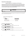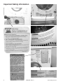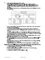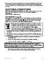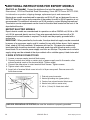
1
Service
This manual is to be used by qualified appliance
technicians only. Maytag does not assume any
responsibility for property damage or personal
injury for improper service procedures done by
an unqualified person.
Compact Dryer
This Base Manual covers general information
Refer to individual Technical Sheet
for information on specific models
This manual includes, but is
not limited to the following:
MDE2400AY*
16023432
Revision 0
©2004 Maytag Services
Important Information
Important Notices for Technicians and Consumers
Maytag will not be responsible for personal injury or property damage from improper service procedures. Pride and
workmanship go into every product to provide our customers with quality products. It is possible, however, that during
its lifetime a product may require service. Products should be serviced only by a qualified service technician who is
familiar with the safety procedures required in the repair and who is equipped with the proper tools, parts, testing
instruments and the appropriate service information. IT IS THE TECHNICIANS RESPONSIBILITY TO REVIEW ALL
APPROPRIATE SERVICE INFORMATION BEFORE BEGINNING REPAIRS.
!
WARNING
To avoid risk of severe personal injury or death, disconnect power before working/servicing on appliance to avoid
electrical shock.
To locate an authorized technician, please consult your telephone book or the dealer from whom you purchased this
product. For further assistance, please contact:
Customer Service Support Center
CAIR Center
Web Site
Telephone Number
WWW.MAYTAG.COM ............................................. 1-800-688-9900
CAIR Center in Canada ........................................... 1-800-688-2002
Amana Canada Product ........................................... 1-866-587-2002
Recognize Safety Symbols, Words, and Labels
! DANGER
DANGER—Immediate hazards which WILL result in severe personal injury or death.
!
WARNING
WARNING—Hazards or unsafe practices which COULD result in severe personal injury or death.
!
CAUTION
CAUTION—Hazards or unsafe practices which COULD result in minor personal injury, product or property
damage.
2
16023432 Rev. 0
©2004 Maytag Services
Table of Contents
Important Information .................................................... 2
Important Safety Information ......................................... 4
General Information
Model Identification .................................................... 8
Serial Label Location ................................................. 8
Model Nomenclature .................................................. 9
Troubleshooting Guide Location ................................. 9
Model Specifications ................................................. 10
Troubleshooting
Troubleshooting General Symptoms ......................... 11
Component Electrical Testing
Thermistor Resistance .............................................. 12
Heater Check Including Thermostats ........................ 12
Motor Check ............................................................. 12
Resetable Thermal Fuse and Hi Limit ....................... 12
Thermistor Check ..................................................... 13
Door Switch Check ................................................... 13
Top Removal ............................................................. 14
Thermostat Removal ................................................. 14
Back Cover and Vent Tube Removal ......................... 14
Heater Removal ........................................................ 15
Wiring Configuration .................................................. 15
Console Removal ...................................................... 16
Circuit Board Removal .............................................. 17
Front Panel/Door/Door Switch/Drum Glide Removal . 18
Drive Belt Removal .................................................... 20
Drum Removal .......................................................... 21
Rear Seal Removal ................................................... 22
Motor/Blower Removal .............................................. 22
Door Reversal ........................................................... 24
Appendix A
Installation Instructions ............................................. 26
Appendix B
Use And Care ........................................................... 39
©2004 Maytag Services
16023432 Rev. 0
3
Important Safety Information
! WARNING
To avoid risk of fire, electric shock, serious injury, or death when using your dryer, follow these basic precautions:
1. Read all instructions before
using dryer.
2. Install dryer according to
Installation Instructions. Refer to
the Grounding Instructions in the
Installation Instructions for
proper grounding of the dryer.
3. Do not dry articles that have
been cleaned in, washed in,
soaked in, or spotted with
gasoline, dry-cleaning solvents,
or other flammable or explosive
substances. Vapors could ignite
or explode.
4. Do not use dryer to dry clothes
which have traces of any
flammable substance, such as
vegetable oil, cooking oil,
machine oil, flammable
chemicals, thinner, etc., or
anything containing wax or
chemicals, such as mops and
cleaning cloths. Flammable
substances may cause fabric to
catch fire by itself.
5. Do not store or use gasoline or
other flammable vapors and
liquids near this or any other
appliance.
6. Do not allow children to play on
or in dryer. Close supervision of
children is necessary when
dryer is used near children, a
safety rule for all appliances.
7. Before dryer is removed from
service or discarded, remove
doors to drying compartment.
8. Do not reach into dryer if
cylinder is revolving.
9. Do not install or store dryer
where it will be exposed to water
and/or weather.
10. Do not tamper with dryer
controls.
11. Do not repair or replace any part
of dryer or attempt any service,
unless specifically recommended
in user-maintenance instructions
or in published user-repair
instructions that you understand
and have skills to carry out, if you
are a consumer.
12. To reduce risk of electric shock or
fire, do not use extension cords or
adapters to connect dryer to
electrical power source.
13. Use the dryer only for its intended
purpose, drying clothes.
14. Always disconnect dryer from
electrical supply before
attempting any service.
Disconnect power cord by
grasping the plug, not the cord.
15. Do not use heat to dry articles
containing foam rubber or
similarly textured rubberlike
materials.
16. Always clean the lint filter after
every load. A layer of lint in the
filter reduces drying efficiency and
prolongs drying time.
17. Use only fabric softeners or
products to eliminate static that
are appropriate for automatic
dryers.
18. Keep your dryer in good condition.
Bumping or dropping dryer can
damage safety features. If
damage occurs, have dryer
checked by qualified service
technician.
19. Replace worn power cords and/or
loose plugs.
20. Do not tumble fiberglass curtains
and draperies unless the label
says it can be done. If they are
dried, wipe out the cylinder with a
damp cloth to remove particles of
fiberglass.
21. Always read and follow
manufacturer’s instructions on
packages of laundry aids. Heed
all warnings or precautions. To
reduce risk of poisoning or
chemical burns, keep products
away from children at all times,
preferably, in a locked cabinet.
22. Never operate dryer with guards
and/or panels removed.
23. Do not operate dryer with
missing or broken parts.
24. Do not bypass safety devices.
25. Keep area around the exhaust
opening and adjacent
surrounding areas free from
accumulation of lint, dust, and
dirt.
26. Interior of dryer and exhaust duct
should be cleaned periodically
by qualified service personnel.
27. Dryer will not operate with
loading door open. DO NOT
bypass door safety switch by
permitting dryer to operate with
door open. Dryer will stop
tumbling when door is opened.
Do not use dryer if it does not
stop tumbling when door is
opened or starts tumbling
without pressing or turning the
START mechanism. Remove the
dryer from use and call
the service person.
28. Remove laundry immediately
after the dryer stops.
29. ALWAYS follow the fabric care
instructions supplied by the
garment manufacturer.
Save These Instructions
4
16023432 Rev. 0
©2004 Maytag Services
Important Safety Information
Electrical Service Information
! WARNING
Electrical Dryers
• 240 VAC, 60 Hz, 30 Amps,
3–wire or 4–wire installations
About Ground Wires
In the event of an electrical short circuit, a ground wire
reduces the risk of electric shock by providing an escape
wire for the electric current.
Standard accepted color coding for ground wires is green
or green with a yellow stripe.
Grounding wires and wires colored like grounding wires
are NOT to be used as current carrying conductors.
To reduce the risk of fire and exposure to combustion
gases, the dryer MUST be exhausted to the outdoors.
DO NOT exhaust dryer air into a window well, gas vent,
chimney or enclosed, unventilated area, such as an
attic, wall, ceiling, crawl space under a building or
concealed space of a building.
! WARNING
To reduce the risk of fire, electric shock, serious injury
or death, all wiring and grounding must conform with
the latest edition of the National Electric Code, or the
Canadian Electrical Code, and such local regulations
as might apply. It is the customer’s responsibility to
have the wiring and fuses checked by a qualified
electrician to make sure your home has adequate
electrical power to operate the dryer.
! WARNING
To avoid risk of personal injury or death due to
electrical shock:
•
•
•
•
•
•
•
•
•
•
•
Observe all local codes and ordinances.
Disconnect electrical power to unit before servicing.
Ground appliance properly.
Check with a qualified electrician if you are not sure
this appliance is properly grounded.
DO NOT ground to gas line.
DO NOT ground to cold water pipe if pipe is
interrupted by plastic, non-metallic gaskets, or other
insulating (non-conducting) materials.
DO NOT modify plug on power cord. If plug does not
fit electrical outlet, have proper outlet installed
by qualified electrician.
DO NOT have a fuse in the neutral or ground circuit.
A fuse in the neutral or ground circuit could result in
an electrical shock.
DO NOT use an extension cord with this appliance.
DO NOT use an adapter plug with this appliance.
DO NOT pinch power cord.
©2004 Maytag Services
16023432 Rev. 0
5
Important Safety Information
6
16023432 Rev. 0
©2004 Maytag Services
Important Safety Information
©2004 Maytag Services
16023432 Rev. 0
7
General Information
Service
Model Identification
Complete registration card and promptly return. If
registration card is missing:
• For Maytag product call 1-800-688-9900 or visit the
Web Site at www.maytag.com
• For product in Canada call 1-866-587-2002 or visit the
Web Sites at www.maytag.com or www.jennair.com
When contacting provide product information located on
rating plate. Record the following:
Model Number:
___________________
Manufacturing Number:
___________________
Serial or S/N Number:
___________________
Date of purchase:
___________________
Dealer’s name and address:
___________________
Keep a copy of sales receipt for future reference or in
case warranty service is required. To locate an authorized
servicer:
• For Maytag product call 1-800-462-9824 or visit the
Web Site at www.maytag.com
• For product in Canada call 1-866-587-2002 or visit the
Web Site at www.maytag.com
Warranty service must be performed by an authorized
servicer. We also recommend contacting an authorized
servicer, if service is required after warranty expires.
Parts and Accessories
Purchase replacement parts and accessories over the
phone. To order accessories for your product call:
• For Maytag product call 1-800-462-9824 or visit the
Web Site at www.maytag.com
• For product in Canada call 1-866-587-2002 or visit the
Web Sites at www.maytag.com or www.jennair.com
Extended Service Plan
We offer long-term service protection for this new oven.
• Dependability PlusSM Extended Service Plan is
specially designed to supplement Maytag’s strong
warranty. This plan covers parts, labor, and travel
charges.
Call 1-800-925-2020 for information.
Serial Label is located in the lower center of the door
opening and back panel.
8
16023432 Rev. 0
©2004 Maytag Services
General Information
Compact Dryer Nomenclature
M
D
E
2
4
0
0
A
Y
W
Color
Brand
M
W
Q
Maytag
Product Type
DE
Listing
W
Y
Z
Y
Dryer Electric
120V-60hz
240V-60hz
Canada 240V-60hz
220-240 V / 50-60 Hz
Marketing Code
Feature Content
2400
White
Bisque
This identifies which
version of production the
unit is.
Feature Package
Troubleshooting Guide Location.
©2004 Maytag Services
16023432 Rev. 0
9
General Information
10
16023432 Rev. 0
©2004 Maytag Services
Troubleshooting Procedures
!
WARNING
To avoid risk of electrical shock, personal injury or death, disconnect power to unit before servicing, unless testing
requires power.
Will Not Run
Will not start or run:
• All wires are hooked up to their corresponding
terminals.
• Dryer is plugged in.
• Blown fuse or circuit breaker.
• Door switch functional...door closed. Check for
error code 3 (See Tech Sheet for code definition).
• Start/Pause switch functional.
• Control Board operational.
• Drive motor functional.
• Check motor capacitor.
Motor runs/ tumbler will not turn:
• Belt off or broken/damaged.
• Idler tension spring too weak or stretched.
• Idler pulley jammed or stuck.
Runs a few minutes and then stops:
• Lint buildup around drive motor.
• Low voltage present.
• Blower impeller blocked in blower
housing.
• Drive motor - start switch contacts stuck closed.
Blows fuses or trips circuit breaker:
• The amperage readings are at 240 volts. One line
will be 24 amps and the other line will be 21 amps.
The neutral line will be at 3 amps. If the above
amperages are present, then the house wiring,
fuse box or circuit breaker should be suspect.
• Shorted heating element to housing.
• Incorrect wiring or a wire shorting to ground.
• Drive motor winding shorting to ground.
Will Not Dry
Will not heat (motor runs):
• Open heating element.
• Hi-Limit trips easily or is open.
• Regulating thermostat trips easily or is open.
• Membrane switch open.
• Check Thermistor.
©2004 Maytag Services
Improper drying/clothes wrinkled/ rough
texture/long dry time:
• Lint filter is not clean.
• Restriction in exhaust.
• Outside exhaust hood damper door stuck closed.
• Exhaust too long, too many elbows, flex ductwork
installed.
• Poor intake air available for the dryer.
• Incorrect tumbler speed. Tumbler belt slipping.
• Blower impeller bound; check for foreign material
in blower area.
• Customer overloading dryer.
• Check clothing labels for fabric content and cycle
selected.
• Clothes too wet due to insufficient spin out by
washer.
Will Not Shut Off
• Check Membrane Pad.
• Check Electronic Control Board.
Troubleshooting the electronic
control circuit:
• Check for miswiring of the electrical connector at
the electronic control board.
Noisy and/Or Vibration
• Thumping Check for loose tumbler baffle, rear
tumbler roller(s) worn or misaligned, out-of-round
tumbler or high weld seam on tumbler.
• Ticking Check for loose wire harness or object
caught in blower wheel area.
• Scraping Check for front or rear bulkhead felt seal
out of position or worn tumbler front bearings.
• Roaring Check for blower wheel rubbing on blower
housing or bad motor bearings.
• Popping or squealing sound. Check for a sticky
or frayed belt.
16023432 Rev. 0
11
Troubleshooting Procedures
!
WARNING
To avoid risk of electrical shock, personal injury or death, disconnect power to unit before servicing, unless testing
requires power.
Component Electrical Testing
Motor check.
Disconnect harness and
test White wire Pin 2 to Red
wire Pin 1. Approx 35 ohms
± 10%
Thermistor resistance 60k ohms.
1
2
CN2
3
Disconnect harness and test
Blue wire Pin 3 to White wire
Pin 2. Approx 29 ohms ± 10%
Resetable Thermal
High Limit Thermostat
Fuse
Less than 1 ohm
Less than 1 ohm
Heater check including thermostats.
240VAC
Heater
Input
Heater check.
To check the heating element only, disconnect the red
wire from the thermostat and check across the red wire
and the blue wire on the power relay. Heater resistance is
approximately 26 ohms. To check the heating element
and thermostats from the console, check across the blue
wire on the power relay and the white to the heater relay
with the connector removed.
POWER HEATER
POWER HEATER
Disconnect harness and
test White wire Pin 2 on
Heater Relay to Blue wire
Pin 1 on Power Relay.
Approx 26 ohms ± 5%
Red wire Pin 1 on
Heater Relay to
Black wire Pin 2 on
Power Relay
Heater Power
12
16023432 Rev. 0
©2004 Maytag Services
Troubleshooting Procedures
!
WARNING
To avoid risk of electrical shock, personal injury or death, disconnect power to unit before servicing, unless testing
requires power.
Thermistor check.
Door Switch check.
Disconnect harness and test Blue wire Pin 2 to Blue
Wire Pin 4. Less than 1ohm
654321
CN1
Remove plug and test from Red wire Pin 1 to White wire
Pin 6. Approx 60K ohms @ room temp.
654321
CN1
©2004 Maytag Services
16023432 Rev. 0
13
Disassembly Procedures
!
To avoid risk of electrical shock, personal injury or
death; disconnect power to unit before servicing.
WARNING
Top Removal
1. Disconnect power supply to unit.
2. Remove 2 screws from dryer back.
4. Remove screws and Thermostats.
3. Slide Top Cover to the rear of the dryer and separate
from cabinet.
Resetable Thermal
Fuse
Hi-Limit
Back Cover and Vent Tube Removal
1. Disconnect power supply to unit.
2. Remove 3 screws and Back Cover.
FRONT
OF
DRYER
SLIDE
Thermostat Removal
1. Disconnect power supply to unit.
2. Remove Top Cover.
3. Remove screws and Heater Shield.
14
16023432 Rev. 0
©2004 Maytag Services
Disassembly Procedures
!
To avoid risk of electrical shock, personal injury or
death; disconnect power to unit before servicing.
WARNING
4. Disconnect Heater Harness plug.
5. Remove 4 screws and Heater Assembly from dryer
back.
3. Pull Vent Tube from the exhaust port on the blower
outlet duct.
Heater Removal
1. Disconnect power supply to unit.
2. Remove Back Cover.
3. Slip Heater Harness from wire tie on the dryer back.
Wiring Configuration
Main
Harness
Heater
Harness
Retaining
C lips
View of the rear of the dryer cabinet
with drum removed showing proper
wire harness routing and location of
retaining clips.
©2004 Maytag Services
16023432 Rev. 0
Motor Harness
15
Disassembly Procedures
!
To avoid risk of electrical shock, personal injury or
death; disconnect power to unit before servicing.
WARNING
6. Remove 2 nuts attaching heater element to cover.
Console Removal
1. Disconnect power supply to unit.
2. Remove Top Cover.
3. Snip wire ties on the Console wire harness.
CAUTION: Do not cut wire tie without having a
replacement on hand. Never reassemble
dryer without wire ties in place.
Note:
16
There are 2 washers between the heater
element housing and the heater cover.
16023432 Rev. 0
©2004 Maytag Services
Disassembly Procedures
!
To avoid risk of electrical shock, personal injury or
death; disconnect power to unit before servicing.
WARNING
4. Remove screw inside the dryer attaching the Console
to the cabinet.
7. Roll Console forward to access wiring on circuit
board.
Circuit Board Removal
5. Unlatch the Console Blank.
1.
2.
3.
4.
Disconnect power supply to unit.
Remove the dryer top.
Remove Console.
Remove 5 screws retaining the Circuit Board.
6. Remove screw on front face and right side of
Console.
©2004 Maytag Services
16023432 Rev. 0
17
Disassembly Procedures
!
To avoid risk of electrical shock, personal injury or
death; disconnect power to unit before servicing.
WARNING
5. Lift Circuit Board from Console housing.
Remove
Loosen
Front Panel/Door/Door Switch/Drum Glide
Removal
1.
2.
3.
4.
Disconnect power supply to unit.
Remove the dryer Top Cover.
Remove Console.
Remove the Toe Panel. Using a plastic Putty Knife or
large coin, disengage the latches located
approximately 2” in on both sides and in the center.
6. Lift and remove door. Remove remaining hinge
screws.
7. Do not remove the 2 upper screws, opposite the
hinge side
5. Remove 1 upper screw attaching the Door Hinge to
the Front Panel. Loosen but do not remove the 1
lower screw attaching the Door Hinge to the Front
Panel. Repeat this step for the lower hinge.
18
16023432 Rev. 0
©2004 Maytag Services
Disassembly Procedures
!
To avoid risk of electrical shock, personal injury or
death; disconnect power to unit before servicing.
WARNING
8. Remove the 2 lower screws opposite hinge side.
12. Lift Front Panel from hanger tab on cabinet.
13. Disconnect the Door Switch wire harness.
9. Do not remove the center screw.
10.Remove 4 Front Panel retaining screws under Toe
Panel .
11. Remove 3 Front panel retaining screws located on
the top of the Front Panel.
©2004 Maytag Services
16023432 Rev. 0
19
Disassembly Procedures
!
To avoid risk of electrical shock, personal injury or
death; disconnect power to unit before servicing.
WARNING
CAUTION: When reassembling Front Panel route the
Light Socket wire harness behind the Door Switch.
This prevents the harness from contacting the
rotating drum during dryer operation.
Drive Belt Removal
1.
2.
3.
4.
5.
Disconnect power supply to unit.
Remove dryer Top Cover.
Remove Console.
Remove Front Panel.
Remove 3 screws attaching Blower Inlet Panel to
cabinet.
14.Service Front Drum Seal and Glides as needed.
6. Lift Inlet Panel from dryer.
SEAL
7. Remove 3 screws retaining Back Cover to cabinet.
8. Release tension on belt by moving Tension Pulley
toward the Drive Motor.
GLIDE
20
16023432 Rev. 0
©2004 Maytag Services
Disassembly Procedures
!
To avoid risk of electrical shock, personal injury or
death; disconnect power to unit before servicing.
WARNING
9. Slide belt forward along drum to the front of the dryer
and remove.
9. Remove 1 screw retaining the Bearing Dust Cap to
the cabinet back.
Drum Removal
1.
2.
3.
4.
5.
6.
7.
Disconnect power supply to unit.
Remove dryer Top Cover.
Remove Console.
Remove Front Panel.
Remove Rear Panel.
Remove Belt.
Remove 4 screws retaining Front Cross Brace.
10. Remove Retainer Ring on drum shaft.
8. Lift Front Cross Brace from dyer.
©2004 Maytag Services
16023432 Rev. 0
21
Disassembly Procedures
!
To avoid risk of electrical shock, personal injury or
death; disconnect power to unit before servicing.
WARNING
11. Slide Retainer Ring and washers from drum shaft.
Rear Seal Removal
1.
2.
3.
4.
5.
6.
7.
8.
Disconnect power supply to unit.
Remove dryer Top Cover.
Remove Console.
Remove Front Panel.
Remove Rear Panel.
Remove Belt.
Remove Drum.
Pull Rear Seal away from dryer back.
Motor/Blower Removal
12.Lift drum from dryer cabinet.
22
1.
2.
3.
4.
5.
6.
7.
8.
Disconnect power supply to unit.
Remove dryer Top Cover.
Remove Console.
Remove Front Panel.
Remove Rear Panel.
Remove Belt.
Remove Drum.
Release Tension spring from Motor Assembly.
16023432 Rev. 0
©2004 Maytag Services
Disassembly Procedures
!
To avoid risk of electrical shock, personal injury or
death; disconnect power to unit before servicing.
WARNING
9. Remove 2 of the 4 screws retaining the motor bracket
to the dryer base. Loosen but do not remove the
remaining 2 screws and slide Motor/Blower Assembly
till the screw heads align with the clearance hole in
the dryer base.
12. Remove Blower Wheel Nut.
Remove
Size 1/2”
Loosen
Size 7/8”
10.Remove Thermistor or Capacitor for servicing.
13. Remove 3 screws retaining Blower Housing to Motor
face.
11. Remove 7 screws to Disassemble Motor/Blower
Assembly Front Cover.
©2004 Maytag Services
16023432 Rev. 0
23
Disassembly Procedures
!
To avoid risk of electrical shock, personal injury or
death; disconnect power to unit before servicing.
WARNING
14.Remove screws retaining Motor to Motor Bracket.
Door Reversal
1. Disconnect power supply to unit.
2. Remove top hinge screw. Loosen but do not remove
lower hinge screw on the top hinge. Repeat
procedure for the lower hinge.
3. Lift the door and remove from dryer.
5. Remove door skin to expose inner door panel.
4. Remove 4 screws around perimeter of door.
24
16023432 Rev. 0
©2004 Maytag Services
Disassembly Procedures
!
To avoid risk of electrical shock, personal injury or
death; disconnect power to unit before servicing.
WARNING
6. Remove the internal door and hinge components and
reassemble them to the opposite side of the Inner
Door Panel.
©2004 Maytag Services
7. Reassemble the outer door skin to the Inner Door
Panel.
8. Reassemble door to Dryer.
16023432 Rev. 0
25
Appendix A
26
16023432 Rev. 0
©2004 Maytag Services
©2004 Maytag Services
16023432 Rev. 0
27
28
16023432 Rev. 0
©2004 Maytag Services
©2004 Maytag Services
16023432 Rev. 0
29
30
16023432 Rev. 0
©2004 Maytag Services
©2004 Maytag Services
16023432 Rev. 0
31
32
16023432 Rev. 0
©2004 Maytag Services
©2004 Maytag Services
16023432 Rev. 0
33
34
16023432 Rev. 0
©2004 Maytag Services
©2004 Maytag Services
16023432 Rev. 0
35
3-WIRE SYSTEM CONNECTIONS
1. Loosen or remove center terminal block screw.
2. Connect neutral wire (white or center wire) of power supply cord to the center, silver colored terminal screw of the terminal block. Tighten screw.
3. Connect the other wires to outer terminal block screws. Tighten screws.
4. Tighten strain relief screws.
5. Insert tab of terminal block cover into slot of dryer rear panel. Secure cover with holddown screw.
1
3
4
1.
2.
3.
4.
5.
External ground connector
Neutral grounding wire (green/yellow)
Center silver-colored terminal block screw
Neutral wire (white or center wire)
3/4 in. (1.9 cm) UL-listed strain relief
2
5
WARNING: If converting from a 4-wire electrical system to a 3-wire, the ground strap
must be reconnected to the terminal block support to ground the dryer frame to the
neutral conductor.
4-WIRE SYSTEM CONNECTIONS
1. Remove center terminal block screw.
2. Remove appliance ground wire (green with yellow stripes) from external ground connector
screw. Fasten it under center, silver colored terminal block screw.
3. Connect ground wire (green or bare) of power supply cord to external ground conductor
screw. Tighten screw.
4. Connect neutral wire (white or center wire) of power supply cord under central screw of
the terminal block.
5. Connect the other wires to outer terminal block screws. Tighten screws.
6. Tighten strain relief screws.
7. Insert tab of terminal block cover into slot of dryer rear panel. Secure cover with hold-down
screw.
1
4
2
3
5
1. External ground connector
2. Green or bare copper wire of power supply cord
3. 3/4 in. (1.9 cm) UL-listed strain relief
4. Center silver-colored terminal block screw
5. Neutral grounding wire (green/yellow)
6. Neutral wire (white or center wire)
6
36
16023432 Rev. 0
©2004 Maytag Services
©2004 Maytag Services
16023432 Rev. 0
37
ADDITIONAL INSTRUCTIONS FOR EXPORT MODELS
(Not U.S. or Canada) Contact the distributor that sold the appliance or: Maytag
International, 1475 East Woodfield Road Schaumburg, Illinois 60173 Phone: 847-273-3100,
for information on product, shipping damage, replacement parts and accessories.
Maytag dryer models manufactured for operation on 60 Hz AC are not designed for use on
50 Hz AC electrical service and conversion of the product from 60 to 50 Hz operation is not
recommended. For additional information on 50 Hz products, contact Maytag International.
The electric service requirements can be found on the data label located on the front of the
dryer behind the door
EXPORT ELECTRIC MODELS
Export electric models are manufactured for operation on either 230/240 volt, 50 Hz or 220
volt, 60 Hz approved electric service. A two-wire approved electrical service with a 30ampere fuse or circuit breaker is required. The dryer must be properly grounded with a
ground wire.
IMPORTANT: When permitted by local codes, the dryer electrical supply may be connected
by means of a new power supply cord kit, marked for use with clothes dryers, that is agency
listed, rated at 240 volts minimum, 30 amperes with two No. 10 copper wire conductors
terminated with closed loop terminals, open-end spade lugs with turned up ends or with
tinned leads. Do not reuse a power supply cord from an old dryer. The power cord or electric
supply wiring must be retained at the dryer cabinet with a suitable agency listed strain relief.
2-WIRE SYSTEM CONNECTIONS
1. Loosen or remove center terminal block screw.
2. Connect neutral wire (white or center wire) of power supply cord to the center, silver
colored terminal screw of the terminal block. Tighten screw.
3. Connect the other wires to outer terminal block screws. Tighten screws.
4. Tighten strain relief screws.
5. Inser t tab of terminal block cover into slot of dryer rear panel. Secure cover with
hold-down screw.
1
4
2
3
1.
2.
3.
4.
5.
External ground connector
Neutral grounding wire (green/yellow)
Center silver-colored terminal block screw
Neutral wire (white or center wire)
3/4 in. (1.9 cm) UL-listed strain relief
5
6
BEFORE OPERATING OR TESTING, be sure the machine is properly grounded.
38
16023432 Rev. 0
©2004 Maytag Services
Appendix B
©2004 Maytag Services
16023432 Rev. 0
39
40
16023432 Rev. 0
©2004 Maytag Services
©2004 Maytag Services
16023432 Rev. 0
41
42
16023432 Rev. 0
©2004 Maytag Services
©2004 Maytag Services
16023432 Rev. 0
43
44
16023432 Rev. 0
©2004 Maytag Services
©2004 Maytag Services
16023432 Rev. 0
45
46
16023432 Rev. 0
©2004 Maytag Services
©2004 Maytag Services
16023432 Rev. 0
47
48
16023432 Rev. 0
©2004 Maytag Services
©2004 Maytag Services
16023432 Rev. 0
49
50
16023432 Rev. 0
©2004 Maytag Services
©2004 Maytag Services
16023432 Rev. 0
51