1
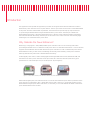
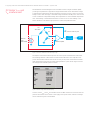
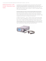
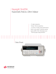
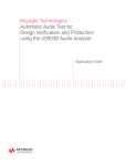
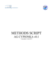
Keysight Technologies
1 mW 50 MHz Power Reference Measurement
with the N432A Thermistor Power Meter
Application Note
Introduction
This application note explains the application procedure for using the N432A with the thermistor mount to
measure the power reference source of power meters. The first part of the article focuses on the fundamentals
of the power reference measurement requirements. The second section provides step-by-step instructions
for performing the measurement using the N432A thermistor power meter. The third part includes the
measurement uncertainty or expected measurement error, which is a basic statistical method of obtaining
the total measurement uncertainty. The final part of the article covers a brief overview of the new Keysight
Technologies, Inc. N432A thermistor power meter.
Why Calibrate the Power Reference?
Measuring or verifying the 1 mW (0 dBm) 50 MHz power reference source is one of the key tasks when
performing the annual service or calibration on RF power meters. In calibration laboratories or service facilities,
engineers and technicians calibrate and measure the power reference in order to maintain the power meter’s
measurement accuracy. In other words, maintaining the accuracy and traceability of the power reference
indirectly minimize the power meter’s measurement uncertainty.
All existing RF power meters, such as the Keysight Technologies EPM-P E4416/17A, EPM E4418/19B, and
the N1913/14A, have a power reference source (also known as a reference calibrator) that has a typical
specification of 1 mW ±0.5% (23 ±3 °C) or ±0.9% (0 to 55 °C) (see Figure 1).
Figure 1. 1 mW (0 dBm) 50 MHz power reference calibrator on power meters
When measuring RF power, the calibration factor corrections done within the power meter (connected with a
power sensor) are referenced to this 1 mW 50 MHz source. That is why prior to performing any direct power
measurement using the power meter and sensor, it is necessary to zero and calibrate the meter to ensure the
power measurement will be accurate.
03 | Keysight | 1mW 50 MHz Power Reference Measurement with the N432A Thermistor Power Meter - Application Note
Why Calibrate the Power
Reference? (continued)
As shown in the Figure 2, the power reference measurement is traceable to the
National Standard (NIST). In order to obtain an accurate measurement when
calibrating the meter’s power reference, the use of a thermistor power meter such as
the Keysight Technologies N432A is recommended. This is because this power meter
combined with the thermistor mount has a very low uncertainty. We shall elaborate
more on the measurement uncertainty in the later portion of this application note.
National standard (NIST)
microcalorimeter
Transfer standard (NIST)
bolometer
Traceability
Reference or working standard
(calibration/standard labs
instruments manufacturer)
End user power meters
N432A + 478A
N432A + 8478B
E4416/17A, E4418/19B
N1911/12/13/14A
Figure 2. NIST traceability of RF power measurement
Measurement setup for
the 1 mW 50 MHz power
reference
The typical measurement setup for testing the reference calibrators uses the N432A
thermistor power meter with a Keysight 3458A 8.5 digit digital multimeter (DMM)
as shown in Figure 3. This setup is widely used by calibration and metrology labs
because the 3458A DMM provides superior accuracy and traceability. However,
depending on the measurement accuracy needed, the 3458A DMM is optional.
The N432A power meter has a built-in internal voltmeter to convert the DC bridge
voltages to watts (or dBm).
Optional
Vcomp (+)
N432A
3458A
Vrf (-)
Cable
adaptor
N4998A
Thermistor power meter & sensor
478A
or
8478B
Figure 3. 1 mW 50 MHz power reference measurement setup
Power meter under test
04 | Keysight | 1mW 50 MHz Power Reference Measurement with the N432A Thermistor Power Meter - Application Note
DC bridge Vcomp and
VRF measurement
The N432A has an internal digitizer that resembles a built-in digital voltmeter (DVM),
providing an equivalent 6.5 digit DVM voltage measurement on the internal DC bridges.
A simplified block diagram of the internal N432A is shown in Figure 4. There are two DC
bridge circuits, the first bridge is called RF bridge and detects the RF power. The second
circuit is called the compensated bridge and compensates for environmental temperature
drift. The readings of the ambient thermistor are used to correct the readings of the
sensor thermistor. This dual bridge operation is called compensated mode.
BIAS driving current
Ruser
100 or 200 Ω
1kΩ
BNC connectors at the rear panel
–
Thermistor
mount
478A or 8478B
RT
1kΩ
+
Signal
conditioning
ADC
Differential amplifier
Figure 4. N432A DC Wheatstone self balancing bridge
The impact of this built-in DVM improves the overall power measurement of the meter.
The resulting benefits of this feature are that an external DVM is not required for the
power measurement and that the overall accuracy of the power measurement is better
than that obtained using only the 432A analog thermistor power meter. Figure 5 shows
the voltage measurements panel in N432A.
Figure 5. N432A voltage measurement display
However, both VCOMP and VRF are available at the two BNC connectors located at the rear
panel of the N432A. This is similar to the legacy 432A power meter, and these voltages
will be measured by the external DMM.
05 | Keysight | 1mW 50 MHz Power Reference Measurement with the N432A Thermistor Power Meter - Application Note
Special thermistor mount
478A-H75/H76 or
8478-H01
Optional specialty thermistor mounts (Figure 6) are used when performing power
reference measurement because these mounts provide the lowest mismatch or standing
wave ratio (SWR) at 50 MHz. The 478A Option H75 or H76, and 8478B Option H01
provide only ≤ 1.05 of SWR at 50 MHz, compare to normal mounts which typically have
a SWR of 1.3. The reason for using these special, factory-tuned low SWR at 50 MHz is
to reduce the mismatch measurement uncertainty when these mounts are connected to
the reference calibrator of the power meters. From past experience, mismatch errors can
significantly impact the overall measurement uncertainty.
Figure 6. Special-tuned low SWR at 50 MHz thermistor mounts
Step-by-Step Power
Reference Measurement
Procedures
1. Connect the equipment as shown in Figure 2.
2. Set the 3458A DMM to measure the DCV.
3. Ensure that the N432A and the power meter under test have been powered on for at least 30 minutes before continuing. (This is the recommended warm up time.)
4. Zero the N432A making sure that the power reference of the power meter under test is turned off.
5. Round the DMM reading to two decimal places and record this reading as V0. This is the voltage measured between the VCOMP and VRF connectors when no RF power is applied (the calibrator reference is turned off).
6. Turn-on the power reference on the power meter under test.
7. Round the DMM reading to two decimal places and record this reading as V1 (the
reading is typically about 80 mV). In other words, V1 is the voltage measured between the VCOMP and VRF connectors when the calibrator reference power is turned on.
8. Disconnect the DMM negative input lead from the VRF connector on the N432A and connect it to the N432A chassis ground.
9. Record the DMM reading result as Vcomp (typically this is about 4.8 V). VCOMP is the
voltage of the temperature compensated bridge.
10. Calculate the power reference oscillator power using Equation 1. The value for R can be typically set as 200 Ω. The CF is the calibration factor for the thermistor mount at 50 MHz. It is typically set as 99%.
11. The expected power measurement results (calculated) should be 1 mW ±0.9%.
P=
2Vcomp (V1 – V0 ) + V 20 – V 21
4 × R × CF
Equation 1
06 | Keysight | 1mW 50 MHz Power Reference Measurement with the N432A Thermistor Power Meter - Application Note
Power Measurement
Uncertainty
Power measurement uncertainty equation
The measurement uncertainty for measuring the 1 mW reference calibrators is based
on the power measurement shown in Equation 2. The equation is a modified version
of Equation 1 and includes the mismatch term (M) to account for the imperfect power
transfer from the power reference (power meter under test) to the thermistor mount.
P=
2Vcomp (V1 – V0 ) + V
2
0
–V
2
1
Equation 2
4 × R × CF × M
M is the maximum (worst case) mismatch uncertainty between the calibrator reference
to be measured and the thermistor mounts connector. It takes the form (1±2Gs x Gd),
where Gs is the power reference reflection coefficient and Gd is thermistor mount reflection
coefficient.
N432A power
measurement uncertainty
model assessment
Typically the power measurement uncertainty assessment is obtained using the uncertainty
tabulated budget model. The assessment starts by collecting all the uncertainty
contributors, in this case they are VCOMP, V0, V1, R, CF, and M. The root sum square (RSS)
of the total uncertainty contributors is then calculated. This is called the RSS method.
Table 1 shows an example of the 1 mW power reference measurement uncertainty
based on set up shown in Figure 2. The content has been simplified and only shows the
individual contributions of each parameter in Equation 2. Refer to Keysight’s application
note Keysight Fundamentals of RF and Microwave Power Measurements, application
note 1449-3, literature number 5989-7083EN for details. The result shows that the total
measurement uncertainty using N432A thermistor power meter and sensor is 0.46%.
Table 1. Measurement uncertainty budget table (with 3458A)
Uncertainty contributors
Units
Value
± Limits
Uncertainty contributed
(standard uncertainty x sensitivity)
Voltage measurement for Vcomp
V
4.8
0.00003845
4.67 x 10⁻⁹
Voltage measurement for V1
V
0.080
0.00000098
6.77 x 10⁻⁹
Voltage measurement for V0
V
0.0023
0.00000032
–2.23 x 10⁻⁹
Bridge resistance measurement, R
Ω
200
0.00250
–7.35 x 10⁻⁹
CF (calibration factor)
Ratio
0.99
0.004 (calibrated by standard lab)
–2.06 x 10⁻⁶
M (mismatch uncertainty)
Ratio
1.00
0.00142 (2 x Gs x Gd)
–1.02 x 10⁻⁶
Root sum square
2.29 x 10⁻⁶
Coverage factor, k = 2 for 95% confidence
2
Expanded uncertainty
4.59 x 10⁻⁶
Expanded uncertainty in % for 1 mW
0.4597
07 | Keysight | 1mW 50 MHz Power Reference Measurement with the N432A Thermistor Power Meter - Application Note
N432A power
measurement uncertainty
model assessment
(continued)
As mentioned earlier, the measurement setup shown in Figure 2 can be simplified by
eliminating the use of the 3458A. The voltage measurements (VCOMP, V0, and V1) will rely
on the internal ADC measurement accuracy of the N432A. Hence the measurement
uncertainty assessment will yield different results. Table 2 shows an example for such a
scenario and the results show a very small difference from the measurement uncertainty
model with the 3458A DMM. The improvement of the voltage measurement from 6.5
digit (N432A internal) to 8.5 digit (3458A) external yield is a non-significant improvement
in terms of the measurement uncertainty. More importantly, in both cases, the CF and
mismatch uncertainty always dominants the total uncertainty.
Table 2. Measurement uncertainty budget table (standalone N432A)
Uncertainty contributors
Units
Value
± Limits
Uncertainty contributed
(standard uncertainty x sensitivity)
Voltage measurement for Vcomp
V
4.78
0.00066730
8.14 x 10⁻⁸
Voltage measurement for V1
V
0.081
0.00001043
7.15 x 10⁻⁸
Voltage measurement for V0
V
0.0023
0.00000709
–4.95 x 10⁻⁸
Bridge resistance measurement, R
Ω
200
0.00250
–7.35 x 10⁻⁹
CF (calibration factor)
Ratio
0.99
0.004 (calibrated by standard lab)
–2.06 x 10⁻⁶
M (mismatch uncertainty)
Ratio
1.00
0.00142 (2 x Gs x Gd)
–1.02 x 10⁻⁶
Root sum square
2.31 x 10⁻⁶
Coverage factor, k = 2 for 95% confidence
2
Expanded uncertainty
4.62 x 10⁻⁶
Expanded uncertainty in % for 1 mW
0.4620
08 | Keysight | 1mW 50 MHz Power Reference Measurement with the N432A Thermistor Power Meter - Application Note
Brief Introduction to the
N432A Thermistor Power
Meter
The N432A meter is the replacement model for the 432A power meter and includes
enhancements and exciting features. This N432A thermistor power meter works
perfectly with Keysight temperature-compensated thermistor mount sensors (478A and
8478B). Together with these sensors, the meter measures RF power from –30 to +10
dBm and cover the frequency range from 100 kHz to 18 GHz. It is the highest-accuracy
power meter offered by Keysight.
The N432A operates on the basis of a DC self-balancing Wheatstone bridge which
shall be elaborated on later. Hence, the N432A is the only RF power meter with a DC
substitution measurement, enabling it to convert RF power to a DC measurement
such as voltage (V) and resistance (Ω). This ability is why the meter is widely used in
metrology and calibration labs worldwide to calibrate power meters and sensors, and for
any application which requires accurate RF power measurement.
In addition to the external VCOMP and VRF connectors at the rear panel, the new N432A
has a built-in digital voltmeter (DVM). It is simply an internal ADC circuit that digitizes
the VCOMP and VRF voltage measurements and displays the results on the front of the
meter. The users can select which measurement results to display, ranging from power
measurement (dBm, watts) to the voltage measurements (VRF, VCOMPENSATED, V0 and V1).
This whole digitization resembles a digital voltmeter (DVM) that’s built inside the power
meter, giving equivalent 6.5 digit DVM voltage measurement results.
09 | Keysight | 1mW 50 MHz Power Reference Measurement with the N432A Thermistor Power Meter - Application Note
Conclusion
Over the years, thermistor-based power meters have been used to measure and calibrate
the 1 mW 50 MHz power reference calibrator of RF power meters because of their
accuracy, reliability, and traceability to standard labs. As shown in the power
measurement uncertainty examples, these power meters (using a special thermistor
mount) provide a very low uncertainty which is around 0.5%.
The use of an external 3458A DMM to measure the VCOMP, V0, and V1 directly from the
N432A power meter is a preferable setup for calibration and the standard lab because it is
a more direct, traceable method and provides greater accuracy.
From the two examples shown, it is clear that the two most significant contributors are the
mismatch error and the CF uncertainty. Hence to maintain low mismatch uncertainty, a
super low reflection coefficient thermistor sensor is to be used. To reduce CF uncertainty,
make sure the sensor is calibrated at the standard metrology labs to maintain consistency,
low uncertainty, and minimum drift.
Reference
1. Radio Frequency & Microwave Power Measurement, Alan Fantom, IEEE,
ISBN: 0 86341 120 7, 1990
2. Keysight Fundamentals of RF and Microwave Power Measurements,
application note 1449-3, literature number 5989-7083EN
3. Keysight N432A Thermistor Power Meter, technical overview, literature number
5990-6168EN
4. Measuring RF Power, Joe Carr, Electronic World, November 1999
5. Keysight EPM-P E4416/17A, service manual, part number E4416-90014
6. Keysight N432A Thermistor Power Meter, user manual, part number N432A-90002
10 | Keysight | 1mW 50 MHz Power Reference Measurement with the N432A Thermistor Power Meter - Application Note
myKeysight
www.keysight.com/find/mykeysight
A personalized view into the information most relevant to you.
www.axiestandard.org
AdvancedTCA® Extensions for Instrumentation and Test (AXIe) is an
open standard that extends the AdvancedTCA for general purpose and
semiconductor test. Keysight is a founding member of the AXIe consortium.
ATCA®, AdvancedTCA®, and the ATCA logo are registered US trademarks of
the PCI Industrial Computer Manufacturers Group.
www.lxistandard.org
LAN eXtensions for Instruments puts the power of Ethernet and the
Web inside your test systems. Keysight is a founding member of the LXI
consortium.
www.pxisa.org
PCI eXtensions for Instrumentation (PXI) modular instrumentation delivers a
rugged, PC-based high-performance measurement and automation system.
Three-Year Warranty
www.keysight.com/find/ThreeYearWarranty
Keysight’s commitment to superior product quality and lower total cost
of ownership. The only test and measurement company with three-year
warranty standard on all instruments, worldwide.
Keysight Assurance Plans
www.keysight.com/find/AssurancePlans
Up to five years of protection and no budgetary surprises to ensure your
instruments are operating to specification so you can rely on accurate
measurements.
www.keysight.com/go/quality
Keysight Technologies, Inc.
DEKRA Certified ISO 9001:2008
Quality Management System
Keysight Channel Partners
www.keysight.com/find/channelpartners
Get the best of both worlds: Keysight’s measurement expertise and product
breadth, combined with channel partner convenience.
www.keysight.com/find/N432A
For more information on Keysight
Technologies’ products, applications or
services, please contact your local Keysight
office. The complete list is available at:
www.keysight.com/find/contactus
Americas
Canada
Brazil
Mexico
United States
(877) 894 4414
55 11 3351 7010
001 800 254 2440
(800) 829 4444
Asia Pacific
Australia
China
Hong Kong
India
Japan
Korea
Malaysia
Singapore
Taiwan
Other AP Countries
1 800 629 485
800 810 0189
800 938 693
1 800 112 929
0120 (421) 345
080 769 0800
1 800 888 848
1 800 375 8100
0800 047 866
(65) 6375 8100
Europe & Middle East
Austria
Belgium
Finland
France
Germany
Ireland
Israel
Italy
Luxembourg
Netherlands
Russia
Spain
Sweden
Switzerland
United Kingdom
0800 001122
0800 58580
0800 523252
0805 980333
0800 6270999
1800 832700
1 809 343051
800 599100
+32 800 58580
0800 0233200
8800 5009286
800 000154
0200 882255
0800 805353
Opt. 1 (DE)
Opt. 2 (FR)
Opt. 3 (IT)
0800 0260637
For other unlisted countries:
www.keysight.com/find/contactus
(BP-09-23-14)
This information is subject to change without notice.
© Keysight Technologies, 2011 - 2014
Published in USA, August 1, 2014
5990-9078EN
www.keysight.com