1
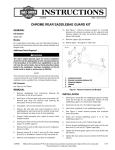
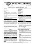
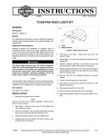
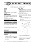
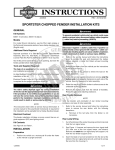
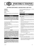
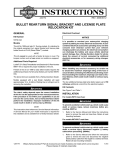
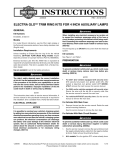
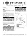
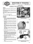
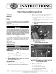
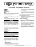
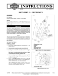
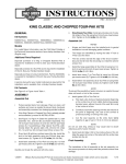
-J04744
REV. 2008-06-26
DETACHABLE TOUR-PAK KIT FOR ELECTRA GLIDE CLASSIC
GENERAL
is05482
Kit Number
2
1
6
53246-09
Models
For model fitment information, see the P&A Retail Catalog or
the Parts and Accessories section of www.harley-davidson.com
(English only).
4
erman
G
5
.
e
.
y
n
Rosto
ck
Separate purchase of LOCTITE® 262 Threadlocker and Sealant
(94759-99) is required for proper installation of this kit. LOCTITE can be purchased from any Harley-Davidson Dealer.
The rider's safety depends upon the correct installation
of this kit. Use the appropriate service manual procedures.
If the procedure is not within your capabilities or you do
not have the correct tools, have a Harley-Davidson dealer
perform the installation. Improper installation of this kit
could result in death or serious injury. (00333a)
1.
2.
3.
4.
5.
6.
3
Fender support (2)
Luggage rack-to-fender support fastener (4)
Forward saddlebag bracket (2)
Grab strap
Fender support fastener, front (2)
Fender support fastener, rear (2)
o p. d e
Additional Parts Required
Figure 1. Remove Luggage Rack
INSTALLATION
Install Docking Brackets and License Plate Holder
NOTE
NOTE
Kit Contents
REMOVAL
w
w
See Figure 5 and Table 1.
w.
Protect the painted surfaces with a soft, clean cloth.
sh
This instruction sheet references service manual information.
A service manual for your model motorcycle is required for this
installation and is available from a Harley-Davidson Dealer.
1.
Install Detachable Tour-Pak Rack Kit to Tour-Pak. Refer
to the instruction sheet provided with kit.
2.
See Figure 5. Apply Loctite 262 to screw (5). Install fender
support cover (29) and docking point bracket (3) with screw
(5) and washer (8). Tighten to 17 ft-lbs (23 Nm).
h d o nli
1.
Refer to service manual to remove saddlebags.
2.
Refer to service manual to remove seat.
3.
Remove the main fuse. See the owner's manual or service
manual.
4.
Refer to service manual to remove Tour-Pak®.
5.
See Figure 1. Remove grab strap fastener (5), washer,
grab strap (4) and forward saddlebag bracket (3). Save
all parts for installation.
n
e
3.
Apply Loctite 262 to screw (5). Install fender support cover
(30) and docking point bracket (2) with screw (5) and
washer (8). Tighten to 17 ft-lbs (23 Nm).
4.
Loosely install left side bracket (15) to docking point
bracket, inserting alignment pin in the hole in the docking
bracket. Install docking point (1) with screw (4) and nut
(11).
Repeat to install right side bracket (14).
5.
Remove rear fender support fastener (6) and fender support (1). Discard fender support cover and fastener. Repeat
for other side.
Loosely assemble the license plate holder (12) with screws
(6), nuts (10) and bracket (16) to brackets (14 and 15).
6.
Center the license plate holder over the tail light and
tighten locknuts finger-tight.
7.
Remove luggage rack-to-fender support fasteners (2).
7.
Tighten bolts (4) to 25 ft-lbs (34 Nm).
8.
Repeat all steps for the other side.
8.
Tighten license plate holder screws (6) to 15-19 ft-lbs (2026 Nm).
9.
Remove adhesive backing from red reflector (13) and
carefully center and align it with the bottom edge of the
license plate holder (12) and press firmly into place.
6.
-J04744
1 of 5
10. Install spacer (9), docking point (1), screw (17) and washer
(7). Repeat for other side.
is05486
2
3
11. Tighten screws (17) to 125 in-lbs (14 Nm).
12. See Figure 1. Install the forward saddlebag bracket (3),
grab strap (4), washer and grab strap fastener (5). Tighten
to 12-15 ft-lbs (16-20 Nm).
4
3
1
Install Antenna and Bracket
1.
Figure 2. Position the antenna bracket (5) as shown to the
inside of the lower saddlebag support bar. Install screws
(6). Tighten the screws to 22 in-lbs (2.5 Nm)
2.
Install the internal tooth lockwasher (4) from the kit onto
the larger threads of the antenna base (1), under the upper
hex nut (3), and insert the antenna base through the hole
in the antenna mounting bracket.
Install the lower hex nut (3) onto the threads of the antenna
base. Tighten the lower nut to 6 ft-lbs (8 Nm).
4.
See Figure 3. Gently remove left side cover (1) by pulling
from frame tubes.
5.
Route antenna cable/wiring between left frame rail and
fender.
6.
Coil excess antenna cable/wiring (2) and use long cable
strap (3) to fasten cable to frame under left side cover (1)
with vehicle wiring harness.
Rosto
ck
3.
7
5
erman
G
.
e
.
y
n
1.
2.
3.
4.
5.
6.
7.
6
Antenna base mount
Antenna mast
Hex nut (thin)
Lockwasher
Antenna mounting bracket
TORX screw (2)
Saddlebag rear support bracket
NOTE
The antenna cable should be routed rearward to the front luggage rack mount, then along the inside of the luggage rack
and down the saddlebag support bar, over to the underside of
the new antenna bracket. Correct the routing if necessary.
FINAL ASSEMBLY
7.
Plug the antenna cable connector into the bottom of the
antenna base. Tighten the knurled nut to secure the connector to the antenna base. Allow slack in the cable at the
antenna base to avoid kinking or binding at the connection.
1.
See Figure 3. Install left side cover (1).
2.
See Figure 4. Apply protective tape (2) to the rear saddlebag mounting bracket (1) on the saddlebag. Repeat
for the other side.
Figure 5. Fasten the antenna cable to the saddlebag
support bar with a cable strap (28) from the kit.
3.
Refer to service manual to install saddlebags.
4.
Refer to service manual to install seat.
w
w
Use a second cable strap to tie the antenna cable to the
frame rail, near the suspension air lines, underneath the
chrome cover. DO NOT secure the cable to the air lines.
9.
w.
Install Tour-Pak
h d o nli
See Figure 2. Install the antenna mast assembly (2)
securely onto the antenna base (1).
Install Tour-Pak. Refer to instruction sheet provided with
the Detachable Tour-Pak Rack kit.
2.
See Figure 5. Install antenna adapter (22) by threading
onto antenna mount joint assembly (24). Plug one end
(connector) of antenna cable (23) onto top of antenna
adapter (22) and tighten knurled nut to secure connector.
Route other end up and through 3/4-inch diameter hole
at the bottom front left side of Tour-Pak and plug into TourPak antenna base.Tighten knurled nut. Make sure enough
cable has been routed into Tour-Pak so that the cable
rests flat on bottom of Tour-Pak. Secure cable in wire clips.
3.
Install grommet (25) in hole in Tour-Pak.
4.
Install antenna mast onto antenna base on the Tour-Pak.
5.
Check antenna for proper operation.
10. Verify that the ignition/key switch is in the OFF position.
Refer to the owner's manual or service manual and follow
the instructions given to install the main fuse.
12. See Figure 5. Cap unused wiring connector with connector
housing (27).
n
e
1.
NOTE
To prevent possible damage to the sound system, verify that
the ignition/key switch is in the OFF position before installing
the main fuse. Refer to the owner's manual or service manual.
11. Test the radio for proper operation.
o p. d e
sh
8.
Figure 2. Antenna Mounting Bracket
To Remove Tour-Pak and Relocate Antenna
-J04744
1.
Remove the mast from the Tour-Pak.
2.
See Figure 5. Remove the antenna cable (23) from the
top of the antenna adapter (22).
2 of 5
3.
Remove antenna adapter and save for installing the TourPak.
4.
Remove Tour-Pak, refer to Detachable Tour-Pak Rack
instruction sheets for procedure.
5.
Install antenna mast to the antenna mount joint assembly
(24).
6.
Check antenna for proper operation.
is05533
1
2
is05540
3
2
1
Rosto
ck
1. Rear saddlebag bracket (2)
2. Protective tape (2)
erman
G
.
e
.
y
n
Figure 4. Apply Protective Tape
o p. d e
1. Side cover
2. Antenna cable
3. Cable strap
w
w
-J04744
sh
Figure 3. Side Cover and Antenna Cable Strap Location
w.
h d o nli
n
e
3 of 5
SERVICE PARTS
is05485
8
2
31
5
11
16
10
1
1
14
9
12
7
8
3
4
Rosto
ck
5
erman
G
.
29
e
.
y
15
n
30
13
o p. d e
17
6
A
25
24
w
w
w.
h d o nli
21
sh
23
27
22
n
26
e
20
19
Figure 5. Service Parts: Detachable Tour-Pak Kit
Table 1. Service Parts Table
Item
Description (Quantity)
License plate relocation kit (includes items 1 through 17 and item 31)
-J04744
Part Number
Not Sold Separately
1
Docking point (4)
53684-96A
2
Bracket, docking point, right
54208-09
3
Bracket, docking point, left
54209-09
4
Screw, TORX 0.375-16 x 1.625 inch (2)
3147
5
Screw, TORX 0.3125-18 x 1.75 inch (6)
4783
6
Screw, hex (2)
3987
7
Washer (2)
6339
8
Washer, plain (6)
6330
4 of 5
Table 1. Service Parts Table
Item
Description (Quantity)
9
Spacers, docking point (2)
6946
10
Nut, flange (2)
7531
11
Nut, flange (2)
7601
12
License plate holder
53376-97
13
Reflector
59988-72A
14
Bracket, right
60911-09
15
Bracket, left
60912-09
16
Bracket, center
60913-09
17
Screw, TORX (2)
94592-98
18
Detachable Tour-Pak rack kit (not shown)
53276-09
19
Nut, hex 1/2-20 (2)
76353-00
20
Lockwasher, 1/2 inch
7129
22
24
25
26
27
28
29
30
31
Rosto
ck
23
erman
G
.
e
.
y
n
Bracket, antenna mounting
76557-09
Adapter, antenna
76219-00
Cable, antenna
76229-00
Joint assembly, antenna mount
76354-00
Grommet
11486
Screw, TORX #10-24 (2)
2441
Connector housing
73103-96BK
Cable strap (4) (not shown)
10006
o p. d e
21
Frame cover, left
Frame cover, right (not shown)
Protective tape (2)
Items mentioned in text, but not included in kit
Antenna
w
w
47502-09
47504-09
54233-09
sh
A
-J04744
Part Number
w.
h d o nli
n
e
5 of 5