1
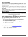
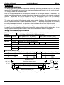
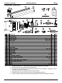
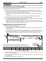
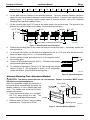
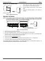
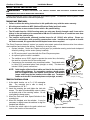
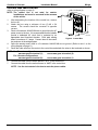
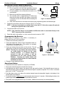
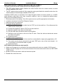
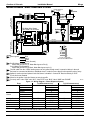
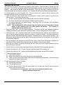
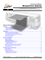
INSTALLATION MANUAL MIRAGE PATIO AWNING RV This publication includes installation for the Direct Response Auto-Retract System with DSK Style Switches TABLE OF CONTENTS Overview ........................................................................................................................................ 1 General Description ................................................................................................................................ 1 Mirage Patio Awning Specifications .................................................................................................... 1 Component Checklist.............................................................................................................................. 2 Installation ..................................................................................................................................... 3 Required Pre-Installation Parameters..................................................................................................... 3 Mounting Plate Layout and Installation ................................................................................................... 3 Alternate Mounting Plate Attachment Method ..................................................................................... 4 Mounting the Awning Unit ....................................................................................................................... 5 Securing the Awning ............................................................................................................................... 5 Electrical Installation .................................................................................................................... 6 Important Notices:................................................................................................................................... 6 Switch Installation ................................................................................................................................... 6 Control Box Installation ........................................................................................................................... 7 Installing the RF Remote Receiver ......................................................................................................... 8 Programming the Receiver ................................................................................................................. 8 Operational Notes: .............................................................................................................................. 8 Ignition Lockout Sensor Installation (Optional) ....................................................................................... 9 Wiring Diagram –Direct Response System .......................................................................................... 10 Testing the System ............................................................................................................................... 11 Standard System Adjustments .................................................................................................. 12 Manual Override ................................................................................................................................... 12 Adjusting the Pitch ................................................................................................................................ 12 Setting the Motor Limits ........................................................................................................................ 13 Adjusting the OUT Limit Switch......................................................................................................... 13 Adjusting the IN Limit Switch............................................................................................................. 13 Carefree of Colorado 052979-003r5 2145 W. 6th Avenue Broomfield, CO 80020 Printed in USA a Scott Fetzer company May, 2013 PROPRIETARY STATEMENT The Mirage Patio Awning is a product of Carefree of Colorado, located in Broomfield, Colorado, USA. The information contained in or disclosed in this document is considered proprietary to Carefree of Colorado. Every effort has been made to ensure that the information presented in the document is accurate and complete. However, Carefree of Colorado assumes no liability for errors or for any damages that result from the use of this document. The information contained in this manual pertains to the current configuration of the models listed on the title page. Earlier model configurations may differ from the information given. Carefree of Colorado reserves the right to cancel, change, alter or add any parts and assemblies, described in this manual, without prior notice. Carefree of Colorado agrees to allow the reproduction of this document for use with Carefree of Colorado products only. Any other reproduction or translation of this document in whole or part is strictly prohibited without prior written approval from Carefree of Colorado. SAFETY INFORMATION WARNING A WARNING INDICATES A POTENTIALLY HAZARDOUS SITUATION THAT, IF NOT AVOIDED, COULD RESULT IN DEATH OR SERIOUS INJURY AND/OR MAJOR PROPERTY DAMAGE. CAUTION A CAUTION INDICATES A POTENTIALLY HAZARDOUS SITUATION THAT MAY CAUSE MINOR TO MODERATE PERSONAL INJURY AND/OR PROPERTY DAMAGE. IT MAY ALSO BE USED TO ALERT AGAINST UNSAFE PRACTICES. NOTE: A note indicates further information about a product, part, or step. Tip: A tip provides helpful suggestions. Safety Notes: Always disconnect battery or power source before working on or around the electrical system. Always wear appropriate safety equipment (i.e. goggles). Always use appropriate lifting devices and/or helpers when lifting or holding heavy objects. When using fasteners, use care to not over-tighten. Soft materials such as fiberglass and aluminum can be "stripped out" and lose the ability to grip. Reference Publications located @ www.carefreeofcolorado.com:' 052979-003 052979-211 052979-301 052979-003r5 Mirage Installation Manual Mirage, Direct Response, Owner's Manual Mirage Service Manual Printed in USA May, 2013 Carefree of Colorado Installation Manual Mirage OVERVIEW GENERAL DESCRIPTION The Mirage Patio Awning offers the coach owner an awning system that provides as much or as little shade as required. The canopies are housed in an aluminum case that easily blends in with the coach side wall. The canopy is made from Sunbrella® fabric. Each unit is equipped with Mirage lateral support arms that are the strongest available on the market. No vertical arms interfere with coach sidewalls or equipment that may be mounted on the sidewalls or sidewall graphics. These arms can also be adjusted to vary the canopy pitch up to 2 feet (it is strongly recommended that service and adjustments be performed by trained technicians). The unique and innovative 110V electronic control system provides Carefree’s Direct Response system with interior pushbutton controls for standard extend/retract functions. At the master control panel the auto-retract system can be engaged to automatically retract the awning in windy conditions. Sensitivity can be set to respond to a variety of wind speed conditions. An optional RF remote is available with the Direct Response system. Two configurations of the Mirage awning are available, a RH (passenger side) and a LH (driver’s side). The motor is located to the front of the awning reducing wiring to keep the awning controls to the front of the vehicle. In the Wiring Diagram the RH configuration is shown; detail A shows the alterations for the LH configuration. Mirage Patio Awning Specifications The following information is for reference only. Specific information is detailed in the installation instructions. 12’ – 21’ [3.66m - 6.4m] (in 1 foot [.305m] increments) LENGTH EXTENSION: 10' [3m] DROP @ MIN. PITCH: 10" [25cm] DROP @ MAX. PITCH: 35" [89cm] Values are approximate, actual dimensions may vary with specific installations. SUPPORT: Lateral Spring Arms 2 for 12' - 18'; 3 for 19' - 21' MOTOR: Tubular Power: CONTROLS: Available in LH or RH configurations 120V, 60Hz, 2.5A Torque: 60nm Direct Response Speed: 14 RPM TM Hardware: White or Black Woven Acrylic (refer to sales literature for colors) Fabric: APPROXIMATE WEIGHT (LBS.) Awning Length Weight Dim B Awning Length Weight Dim B Awning Length 12 134 6.5in 15 160 11.25in 19 13 143 16 169 20 14 152 17 177 21 18 186 22 COLOR: A (Awning Length) Back Plate (Awning Case) 1 1/2" (ref) Weight 194 203 211 220 5.57" Dim B 17in 1 1/4" 3" (ref) 8" Mounting Plate (ref) B Lateral Arm Mount (ref) 6 3/8" B MIRAGE007a Figure 1. General Description - Mirage Patio Awning. 1 052979-003r5 Carefree of Colorado Installation Manual Mirage COMPONENT CHECKLIST 2 6 1 8 5 3 4 RV O WNE R WITH 7 Direct Response Electronic Components 13 12 11 'S M ANU AL MIRA DIREC GE T RESP ONS E This manu spec al appli ific mod es to inclu e ded for theare labelall models optio ed appr listed nal auto opria . Deta -retra tely. Operils and ct and proc optio ational instredures nal remo uctio uniq te cont ns are ue to also rol. Remote Control (Direct Response) 15 9 16 18 17 Ignition Lockout (Optional - Direct Response) 19 10 20 21 14 MIRAGE049 ITEM DESCRIPTION 1 Awning Assy 2 Mounting Plate 3 Screw, Rolock 4 Screw, Lag 5 Backing Plate 6 Backing Plate Cover 7 Hex Key 8 Owner's Manual 9 Control Box 10 Screw, Pan Head 11 Switch Plate 12 Switch Assy 13 Switch Mount 14 Cable 15 RF Receiver, 433MHz 16 Screw, Phillips Truss Head 17 Cable 18 Remote Control Key FOB, 433MHz 19 Sensor, Ignition Lock-Out 20 Splitter 21 Cable Notes: 1. 2. 3. 4. 5. 6. 3/8 x 1 1/2 1/4 x 1 1/2 7mm x 133mm #8 x 3/4 60” #6 x 1/2 60” 60” QTY NOTE 1 1 1 12 3 6 6 1 2,3 1 3 1 4 1 4 1 4 1 1 1 2 1 1 5 1 1 2 Specific awning configuration is specified at time of order, including the awning length, LH or RH configuration, fabric etc. Check awning assembly against original purchase order. Hex key (item 8) is used with motorized awnings only. Place hex key (item 8) and Owner's Manual (item 9 with RV owner information. Installation manual, if included, is for installer reference. Mounting screws are included with switches and switch plate. Additional remote control Key FOBs may be ordered separately (SR0015). Remote Control and Ignition Lock-Out are optional equipment that must be specified at time of order. 2 052979-003r5 Carefree of Colorado Installation Manual Mirage INSTALLATION IT IS RECOMMENDED THAT THREE PEOPLE INSTALL THE AWNING DUE TO THE SIZE AND WEIGHT OF THE COMPONENTS! REQUIRED PRE-INSTALLATION PARAMETERS Prior to installing the awning, the installer must determine the layout of the specific construction elements to successfully assemble and mount the awning. 1. Determine the location, size and type of structural framing in the area where the awning is to be mounted. There must be structural framing at the awning mount locations. Fiberglass or sheet metal siding alone is NOT strong enough to support the weight of the awning! If the framing is not obvious, it may be possible to use a stud finder or other similar device to locate the frame. If in doubt, contact the coach manufacturer to determine the type and position of the structural frame. 2. Determine the mounting locations for the control box and switch assemblies. For 110VAC installations, the installer must provide enclosed junction boxes for all wire splices. Boxes are required in conformance with prevailing construction codes. At the control box location, AC input is required. It is recommended that the installer provide a dedicated AC circuit for the awning system that is protected by an appropriate sized fuse/circuit breaker. Each patio awning draws a maximum of 3 amps. MOUNTING PLATE LAYOUT AND INSTALLATION 1. Determine the location of the awning: Mounting area must be plumb and clear of obstacles; The mounting plate is 9" shorter than the awning (w/ standard end caps); 6" shorter than the back plate. (Reference Figure 1) The awning is factory set with minimum pitch. Mounting height above a door opening or slide-out room must be adjusted for a greater pitch. The chart below provides the minimum distance from the top of a protrusion to the bottom of the mounting plate when the awning is set at MINIMUM and MAXIMUM pitch: Bottom of Case Bottom of Case 5º B 10" Maximum Height of Projection Minimum Pitch Travel Path 119" A 35" 18º Minimum Height (B) is measured from the uppermost edge of the projection (i.e. door, slide-out room flange) to the bottom of the mounting plate. The value given is a minimum requirement, adjust upward as required to clear casing, trim etc. Door Width (A) B @ MINIMUM PITCH B @ MAXIMUM PITCH 0” 2.5" 2.5" 12” 3.25" 5.75" 18” 4.25" 8.25" 24” 5.25" 10.75" 30” 6.25" 13.25" Maximum Pitch 36” 7.25" 15.75" 114" mirage008b 42" 8.25" 18.5" 48" 9 20.5" Figure 2. Mounting Height VS Pitch. 2. Mark the mounting plate position with a chalk line ensuring that it is parallel to the ground. Include the end points of the mounting plate. 3. Use a non-permanent method of marking to temporarily mark the location of the structural framing in the mounting area. 4. Transfer the frame pattern to the mounting plate. 3 052979-003r5 Carefree of Colorado Installation Manual Mirage 5. Below is the minimum number of required mounting locations. Each position uses two screws. Awning Length # of Locations 12' 13' 14' 15' 16' 17' 4 18' 19' 20' 21' 6 5 22' 6. On the plate mark the location of the mounting locations. The inner mounting locations should be spaced as evenly as possible between the outer mounting locations. Locations must match the frame location pattern. If a mounting location cannot match a structural member, refer to the "Alternate Mounting Plate Attachment Method" below. 7. On the mounting plate drill 7/16” holes at the marks made in the previous step. The grooves in the plate are the vertical locations for the holes. Each location has two holes. 4 1/2" (ref) Grooves O 7/16” .5" (ref) 3" (ref) 18” Max (typ) Hole Pattern to Match Structural Frame MIRAGE004b Figure 3. Mounting Plate Hole Drill Pattern. 8. Position the mounting plate on the coach wall using the marks from step 2. Horizontally position the plate as required. 9. On one end of the plate, use the plate as a template and drill an 11/32” pilot hole into the structure. Attach the plate using a 3/8-16 x 1 1/2 thread cutting screw. 3.25" 10. Confirm position of plate and repeat step 6 on the opposite end of the mounting plate. .5" 11. Continue to drill and attach using the 3/8-16 x 1 1/2 thread cutting screws until all mounting holes are done. 12. For motorized configurations. Drill one (1) 1/2” hole through outer wall as shown in Figure 4. RH configuration is shown, for LH configuration reverse end location. (Hole is behind the awning motor.) MIRAGE005 Alternate Mounting Plate Attachment Method CAUTION THIS METHOD SHOULD BE USED ONLY AS REQUIRED. THE STRUCTURE AS DESCRIBED ABOVE. When it is not possible to attach into structure or if the screws will be exposed inside the coach, an 7/16 Holes thru Wall alternate method is to use a backing plate and cover. The installer must furnish the 3/8 bolts, washers and lock nuts. 1. Using the mounting plate as a template, drill 7/16” holes through the wall. The inside of the wall must be accessible. 3/8 Bolt 2. Attach as shown in Figure 5 using a backing plate and cover. Torque nuts to 50 in-lb. Figure 4. Cable Routing Hole. PRIMARY ATTACHMENT MUST BE INTO 3/8 Lock Nut Washer Cover Backing Plate Mounting Plate MIRAGE014 Figure 5. Alternate Mounting Method. 4 052979-003r5 Carefree of Colorado Installation Manual Mirage MOUNTING THE AWNING UNIT 1. While lifting the awning, route the awning motor wires through the 1/2” hole drilled previously. 2. Set the awning into the hooks of the mounting plate. 3. Adjust the horizontal position of the awning as required. Back Plate Mounting Plate MIRAGE018 Figure 6. Mounting the Awning. SECURING THE AWNING NOTE: This procedure requires opening the awning. For motorized awnings, follow the Manual Override instructions on page 12. For motorized awnings, these steps can be done after the electrical installation when motorized power is available. Drill in this area O 3/16” Thru Ream case only to O 5/16” 1/4 x 1 1/2 Lag Screw (3 plcs) MIRAGE010 Figure 7. Securing the Awning. 1. Adjust the awning horizontally as required. 2. Open the awning approximately 3 feet to access the back panel of the awning case. 3. Drill three (3) 3/16” holes through the case, mounting plate and into wall (do not go through interior surfaces of wall) in the approximate areas shown above. 4. Ream out the holes in the case only to 5/16”. 5. Attach the awning case to the mounting plate and wall using three (3) 1/4 x 1 1/2 lag screws. 6. From inside, seal the wires and access hole with a quality silicone sealant. This completes the basic awning installation. For manual configurations, no further action is required. For motorized configurations, proceed to the next section "Electrical". 5 052979-003r5 Carefree of Colorado Installation Manual Mirage ELECTRICAL INSTALLATION WARNING ALWAYS DISCONNECT THE VEHICLE BATTERY AND ELECTRICAL SOURCES BEFORE WORKING WITH ELECTRICAL WIRING AND COMPONENTS. These instructions are for the Direct Response Auto-Retract System. For alternate control systems, follow the directions included with the electronics package. IMPORTANT NOTICES: Failure to follow the wiring instructions in this publication may void the motor warranty. All wiring must conform to NEC (National Electrical Code) and local codes. DO NOT wire two or more motors to one switch—No parallel wiring. The SO cable from the 110VAC awning motor can only pass directly through a wall, it can not be laid up in the wall and must be connected to NM wire or individual wires in conduit no more than 6 inches past the point of entry. The installer must provide enclosed junction boxes for all 110VAC wire splices. Boxes are required in conformance with prevailing construction codes. Installers are required to furnish the flush mounted, UL approved electrical duplex boxes where required. The Direct Response electronic system is a premier auto-retract system that detects motion from adverse wind conditions and retracts the awning. Sensitivity is set by the user. System includes: Control box, Master control panel (w/ pushbutton awning control and windspeed sensitivity setting), motion sensor (factory installed). An RF remote control is provided with the Direct Response system. Green An optional ignition lockout is available. Red Black The switches use a 5VDC signal to operate the control box; eliminating the need for a junction box for the control panel. Components are connected using terminated cables. Terminated cable Yellow Green is 4-wire RJ11 terminated phone cord (straight, no twist). This does not Red include 110VAC power connections. Black NOTE: Cable lengths of the furnished cables are listed in the chart with the system wiring diagram. If a connection requires a length greater than the supplied cable, the installer must provide a terminated jumper cable from the box location to the cable end. Terminated cables are 4-wire RJ11 terminated phone cord (straight, no twist). Yellow Cables are 4-wire RJ11 terminated phone cord (straight, no twist). RTA031 SWITCH INSTALLATION 1. At the switch location, cut a 4” x 3 3/4” rectangular hole. The mounting box is able to clamp to thicknesses from 1/4” to 1”. 2. Insert the mounting box and tighten the latch tab screws. The tabs will automatically rotate to clamp on the back side of the mounting surface. Do not over tighten the clamp screws. 3. Mount the Patio and Wind Speed Switches in the mounting box. 4. Mount the faceplate onto the switches. It may be necessary to slightly loosen the switches to align the faceplate and switches. 5. Connect the switch cable to the patio switch and route to the location of the control box. 6 Latch Tab Switch Cable to Control Box Patio Switch 3 3/4” 4” Mounting Box Wind Speed Switch Face Plate MIRAGE022a Figure 8. Switch Installation. 052979-003r5 Carefree of Colorado Installation Manual Mirage CONTROL BOX INSTALLATION #8 x 3/4 Screw (2) (refer to wiring diagram on page 9) NOTE: The control box is not rated for exterior installations and must be mounted in the INTERIOR of the vehicle. 1. After determining the location of the control box, remove the box lid. 6 1/2” (typ) 2. Attach the box using a minimum of two (2) #8 x 3/4 screws. The screws should be mounted in opposite corners. 3. Route a 2-conductor 14AWG NM wire w/ ground from the AC power source to the box. It is recommended that the installer 2 3/8” RTA0033a provide a dedicated AC circuit that is protected by an appropriate sized fuse/circuit breaker. Each patio awning Figure 9. Control Box. draws a maximum of 3 amps. Connect wires to the control box as shown in the wiring diagram. 4. Splice the awning motor wires to a 3-conductor 14AWG NM wire w/ ground. (Refer to note 1 on the wiring diagram on page 9.) 5. Route the cable wire from the motor to the control box and attach the wires to the terminals as shown. NOTE: For RH motor configurations: RED WIRE goes to terminal (1); For LH motor configurations: RED WIRE goes to terminal (2); 6. 7. BLACK WIRE goes to terminal (2). BLACK WIRE goes to terminal (1). Connect the cable from the switch panel to “ACC” in the control box. Connect the cable from the motion sensor to “AMD” in the control box. NOTE: Use the slot cutouts in the box to route the phone cables. 7 052979-003r5 Carefree of Colorado Installation Manual Mirage INSTALLING THE RF REMOTE RECEIVER 1. Determine the location of the optional RF receiver: 4 3/16” 1.1 Do not mount the unit near heat producing elements such as LP appliances or engine exhaust components. 1.2 For best reception, do not mount the unit near or on a metal surface. 1” 1.3 Mount the unit with the antenna pointing up. #6 x 1/2 1.4 The included cable is approximately 60 inches long. Screw (2) 3 7/8” RTA034 Mount the unit close enough to the splitter or control box so that the cord can be connected without stressing the Figure 10. RR24 RF Receiver. connections. 1.5 Allow room below the box to access the connector jack, programming button and indicator light. Program Mode Press to Learn Transmitter TO EYE PORT on RP24 RR24 UP 2. Position the control box and secure using two (2) #6 x 1/2” screws. NOTE: If the box is mounted on a surface that is less that 1/2” thick, the screws will protrude through the opposite side of the surface. 3. Connect the cable to the receiver. NOTE: If the Lock-Out Sensor is not installed, the Receiver cable is connected directly to the "EYE" connector of the control box. 4. Route the cable to the splitter; or, to the control box and connect to “EYE”. Press to Learn Transmitter Program Mode When adding or replacing a key FOB it is necessary to program the receiver for the transmitter 1. Power to the control box must be on. 2. Press and release the “Press to Learn Transmitter” button on the bottom of the receiver box. The receiver is in program mode when the red light comes on. 3. Press and release the stop button on the remote. The red Stop light will go out after the receiver learns the remote signal. NOTE: Pressing the stop button will cause the blue up arrow button to default as the close (retract) function. If a function button is pressed to train the receiver, it will be programmed as the close (retract) button. Example: Pressing the bottom button will program the bottom button for retract and the top button as extend. 4. Repeat for each additional remote. TO EYE PORT on RP24 Programming the Receiver Indicator Light UP Program Button DR020 Figure 11. RF Receiver. Operational Notes: Transmitter and receiver operate on a frequency of 433 MHz. The receiver exits the program mode after ten seconds. If the light does not come on above, the memory is full and must be cleared. If the light still does not come on, check the continuity of the cord between the boxes and repair or replace as required. Pin 1 of the 1st connector goes to pin 1 of the 2nd connector etc. If the light does not go out in above, the receiver already knows the transmitter's signal or the battery in the remote needs to be replaced. To clear the memory: PRESS AND HOLD the transmitter learn button for 5 seconds. While holding the button, the indicator light should be OFF for the full 5 seconds then come on. The system may be programmed for up to 5 remotes. Additional remotes may be ordered separately. 8 052979-003r5 Carefree of Colorado Installation Manual Mirage IGNITION LOCKOUT SENSOR INSTALLATION (OPTIONAL) Two ignition lockout sensors are available with the Direct Response System. The STD ignition lockout module disables the extend function when the module receives a current through a switched 12VDC circuit.. The RTL ignition lockout module will fully retract the awning and disable the extend function when the module receives a current through a switched 12VDC circuit. A switched 12VDC source is a line that is "hot" when the ignition switch is in the on position; or, a 12VDC circuit through a relay that is "hot" when a specific condition is met (i.e. releasing the parking brake). Relays are not furnished with this kit. 1. 2. 3. 4. Disconnect power to the awning. Shut off the power source or pull the appropriate circuit breaker. Locate the control box for the Direct Response System. Open the cover of the control box. For Single Awning Applications: 4.1. Disconnect the remote receiver cable from the "EYE" port in the control box. Do not disconnect the cable from the receiver box. 4.2. Connect the supplied 6" cable to “EYE” port in the control box. 4.3. Attach the splitter to the other end of the cable. 4.4. Plug the cable from the remote receiver into the splitter. 4.5. Attach the Lock-Out Sensor to the end of the 60" cable. Route the cable as desired and connect the cable to the splitter. 4.6. Proceed to step 6. 5. For Multiple Awning Applications: 5.1. The module may be connected to the control box as described for single awning applications; OR, 5.2. The module may be directly connected to any open "EYE" port on any of the control boards. It is not necessary to use the short cable or splitter. 5.3. Proceed to step 6. NOTE: Wires to the module are not pin specific. 6. Attach one 18-gauge wire to a terminal of the sensor and route the wire to a suitable 12VDC ground. 7. Attach a second 18-gauge wire to the second terminal of the sensor and route the wire to a SWITCHED 12VDC source. 8. Bundle and secure the sensor, cable and wires as required. 9. Reattach the control box cover. 9 052979-003r5 Carefree of Colorado Installation Manual Mirage WIRING DIAGRAM –DIRECT RESPONSE SYSTEM Sensor 3 Conductor 14AWG NM Wire w/ Gnd AMD Sensor RH Motor Wire Shown See Detail A for LH Motor grn 6 Ignition Lockout Sensor (Optional) 4 Rear View Switch Panel Key Pad To 110VAC 3 4 5 Ribbon Cable Remote grn NOTES: 2 Patio Splitter wht blk 1 UP Wind Speed DSK EYE AUX SUN 2 Conductor 14AWG NM Wire w/ Gnd wht blk RED 1 BLK 2 WHT 3 4 5 GRN 6 7 12VDC Ground Program Mode Awning #1 RED BLK WHT GRN RF Receiver Press to Learn Transmitter 3 Ignition Switched +12VDC TO EYE PORT on RP24 5 BLK 1 RED 2 WHT 3 4 5 GRN 6 7 Detail A Red For LH Configuration Black Reverse Red & Black Wires White Green (Ground) For RH Motor Configurations: Motor Red goes to Pin (1); Motor Black goes to Pin (2) For LH Motor Configurations: Motor Red goes to Pin (2) Black; Motor Black goes to pin (1) The SO cable from the 110VAC awning motor can only pass through a wall, it cannot be laid up in the wall and must be connected to NM wire or individual wires in conduit no more than 6 inches past the point of entry. Splitter is used only when Optional Lock-Out Sensor is installed. Connect RF Receiver directly to “EYE” if Lock-Out is not installed. Wires for the Ignition Lock-Out Sensor are not pin specific. Wire Legend: 6 For early units: Label “DSK” was “ACC”; Label “EYE” was “BUS”; Label “AMD” was ”SHAKE” DR012a Figure 12. Wiring Diagram – Direct Response System. TO (RH CONFIGURATION) TO (LH CONFIGURATION) FROM Motor Red Control Box Control Box 1 2 Black 2 1 White 3 3 Ground 6 6 AC Power White Control Box 4 Control Box 4 Source Black 5 5 Ground 7 7 Awning Sensor 10’ Cable Control Box “AMD” Control Box “AMD” Patio Switch 60“ Cable Control Box “DSK” Control Box “DSK” Splitter 60" Cable Control Box "EYE" Control Box "EYE" Receiver 60” Cable Splitter Splitter Ignition Lockout 60“ Cable Splitter Splitter Notes: 1. Cable lengths are the lengths of the furnished cables. If a connection requires a length greater than the supplied cable, the installer must provide a terminated jumper cable from the box location to the cable end. 10 052979-003r5 Carefree of Colorado Installation Manual Mirage TESTING THE SYSTEM The function LEDs (extend, retract and stop) perform a dual function. When the button is pressed, the LED illuminates. The LED stays illuminated during the selected operation and after the awning has fully extended or retracted. This provides an indicator of the awning position. When the stop button is pressed, the LED will illuminate and stay on until a function is pressed. If on, it indicates that the awning is partially extended/retracted. All function buttons are press ON/press OFF. The auto-functions will continue until the awning is fully extended/retracted or when the stop button is pressed. 1. While observing the control panel, have a second person initiate 110VAC power to the coach and awning system. The following should occur: 1.1 The Auto-Retract and Wind Speed LEDs should illuminate briefly then extinguish. 1.2 The Power ON/OFF and function/position LEDs will briefly illuminate. 1.3 The system then goes to the default settings: The POWER “ON”, AUTO-RETRact “ON” and MEDIUM Wind Speed LED will be on. NOTE: The function/position LEDs (extend, stop and retract) will not be illuminated. During power up the controller does not retain position information. The controller is updated with the first function used. 2. Press the POWER “OFF”. ALL LEDs should extinguish. The POWER ON/OFF button disables all functions including Auto-Retract and the optional RF remote if installed. It does not disconnect the 110VAC power. 3. Press the POWER “ON”. Press the EXTEND button, the LED should illuminate while the awning extends and stay on after the awning auto-stops. Observe the awning, it should fully extend. The system performs an auto-tension action when the awning is fully extended. The awning rolls in reverse to tension the fabric. The auto-tension feature works only with the extend function when the awning is fully extended or the stop button is pushed while extending. 4. After the awning is fully extended, press the RETRACT button, the EXTEND LED should extinguish and the Retract LED should illuminate while the awning is retracting. Press the STOP button. 5. When the STOP button is pressed, the awning will stop, the RETRACT LED should extinguish and the STOP LED should illuminate. 6. Press the RETRACT button, allow the awning to retract fully, the Retract LED will illuminate and stay lit. 7. Press the AUTO-RETRACT OFF. The AUTO-RETRACT and WIND SPEED LEDs should go out. 8. Press the AUTO-RETRACT ON. Press each Wind Speed button and confirm that the LEDs illuminate. 9. Test the Auto-Retract function: 9.1 Fully extend the awning. 9.2 With the AUTO-RETRACT ON, set the WIND SPEED to the lowest setting. 9.3 Create a firm but gentle vertical rocking motion with the leading edge of the awning. The awning should retract after 2-3 seconds of the motion. 10. If the optional Ignition Sensor is installed: 10.1 Partially retract the awning. 10.2 Turn the ignition key ON. 10.3 Press the EXTEND button. The LED should flash for 2 seconds then shut off and the previous function LED will come back on. For problems not covered above, refer to the service manual available on-line @www.carefreeofcolorado.com 11 052979-003r5 Carefree of Colorado Installation Manual Mirage STANDARD SYSTEM ADJUSTMENTS MANUAL OVERRIDE Wall If 110V power is not available to the coach, the Mirage awning can still be safely retracted using the manual override. The bypass may be accessed from inside the case on the motor Remove Screw housing or from the top of the case above the motor housing. and Rubber Well Nut To use the inside bottom access: The awning must be open a to Access Manual minimum of 8” to afford access to the override. Overide (7mm Hex) To use the top bypass access: Remove the screw and well nut that is used to secure the end cap. Top View 1. Chuck the 7mm hex key into a 3/8” battery powered drill. 2. Insert the hex key into the manual override on the awning. For the top access, it will be necessary to locate the hex by 7mm Hex feel; it is not visible with the key inserted in the hole. Manual Override 3. Operate the drill in the forward (clockwise) direction to close the awning. Reverse the drill to open the awning. Wall NOTE: When using the bottom override, the awning Bottom View MIRAGE028 can only be closed within 6-8”. It will be Figure 13. Manual Override Access. necessary to use the top access to close the awning completely. 4. When done, return the screw and well nut to the top of the case if removed. ADJUSTING THE PITCH CAUTION DURING INSTALLATION OR WHEN THE PITCH OF THE AWNING IS ADJUSTED, IT IS IMPORTANT THAT THE LEAD RAIL IS PARALLEL TO THE AWNING HOUSING. 1. 2. Extend the awning fully. 3/4” Adjustment Nut On one end, loosen the 6mm hex screw located on the spring 3/4” Nut arm knuckle. On Side of Knuckle 3. SLIGHTLY loosen the 3/4” nut on the side of the knuckle. 4. Turn the 3/4” adjustment nut located on the bottom of the knuckle. 6mm Hex Screw CLOCKWISE raises the pitch, COUNTERCLOCKWISE lowers the pitch. Coach Wall NOTE: When raising the pitch, it is helpful to have a second person lift up on the lead rail. 5. Repeat steps 2 through 4 for the other end. Note the caution Lead Rail (ref) information above. 6. When the pitch adjustments are completed, tighten the 6mm screw and the 3/4” nut on the side of the knuckle. When the pitch is adjusted, it is necessary to adjust the angle of 6mm Hex Screw the lead rail for the awning to close correctly. 3/4” Nut MIRAGE024 7. SLIGHTLY loosen the 3/4” nut on the side of each arm knuckle on the lead rail. Figure 14. Pitch Adjustment. 8. Turn the INSIDE 6mm hex screws of each knuckle to increase or decrease the angle of the lead rail. The face of the lead rail should be parallel with the coach wall. 9. When the lead rail adjustments are completed, tighten the 3/4” nut on the side of the knuckles. 12 052979-003r5 Carefree of Colorado Installation Manual Mirage SETTING THE MOTOR LIMITS The motor limit switches are preset at the factory for best operation of the awning. The “OUT” limit switch is used to stop the motor when the awning is fully extended. The “IN” limit switch is used to stop the motor when the awning is fully retracted. The “IN” limit is NOT USED when the Direct Response system is installed. Decrease Run Time Decrease Run Time Increase Run Time “OUT” Limit Switch “IN” Limit Switch Previous Configuration Decrease Run Time Previous Configuration Decrease Run Time “IN” Limit Switch “OUT” Limit Switch Increase Run Time Current Configuration Increase Run Time LH Motor RH Motor Wall Increase Run Time Current Configuration MIRAGE023 Figure 15. Motor Limit Switches. The limit switches are located inside the case, near the end cap. It is necessary to extend the awning to access the switches. NOTE: There are two (2) motor limit switch configurations. Before making adjustments, visually inspect the limit switches to determine which configuration is installed in the awning. Use the illustration above to determine the correct turning direction for the adjustments. Adjusting the OUT Limit Switch NOTE: During normal operation, the awning will extend out then roll back slightly to tension the fabric. 1. Extend the awning out completely. 2. Confirm that the arms are fully extended. The motor should stop and the fabric should be tight. 3. If the motor continues to run, the fabric will sag; use a 4mm allen wrench to turn the "OUT" limit switch to DECREASE the motor run time. 4. If the motor quits before the arms are extended; use a 4mm allen wrench to turn the "OUT" limit switch to INCREASE the motor run time. NOTE: It is best to make the adjustments in increments of a single turn. 3 full turns of the screw equals approximately 2” of fabric extension. 5. Extend and retract the awning several times to confirm that the adjustment is correct. 6. Repeat as required until the awning extends correctly. Adjusting the IN Limit Switch NOTE: The “IN” limit switch is not adjusted when the Direct Response system is installed. The system electronics monitors the motor and shuts the motor off when the awning is fully retracted. If the IN limit switch is accidentally adjusted, the motor may shut off before the awning is fully closed. If this occurs, turn the "IN" adjustment screw to INCREASE the motor run time. It is not necessary that the screw matches the closed position. The Direct Response electronics control the closed position. NOTE: It is normal for the lead rail to slightly relax after the awning closes completely. 13 052979-003r5