1
High-speed, High-accuracy CCD Laser Displacement Sensor
LK-G Series
KEYENCE CORPORATION
1-3-14, Higashi-Nakajima,
Higashi-Yodogawa-ku, Osaka,
533-8555, Japan
Phone: 81-6-6379-2211
Fax: 81-6-6379-2131
KEYENCE CORPORATION OF AMERICA
Phone: 201-930-0100 Fax: 201-930-0099
KEYENCE (MALAYSIA) SDN BHD
Phone: 03-2092-2211 Fax: 03-2092-2131
KEYENCE DEUTSCHLAND GmbH
Phone: 06102-36 89-0 Fax: 06102-36 89-10
KEYENCE (THAILAND) CO., LTD.
0
Phone:
02-369-2777 Fax: 02-369-2775
KEYENCE (UK) LIMITED
Phone: 01908-696900 Fax: 01908-696777
KEYENCE TAIWAN CO., LTD.
Phone: 02-2718-8700 Fax: 02-2718-8711
KEYENCE FRANCE S.A.
Phone: 01 56 37 78 00 Fax: 01 56 37 78 01
KEYENCE (HONG KONG) CO., LTD.
Phone: 3104-1010 Fax: 3104-1080
KEYENCE ITALIA S.p.A.
Phone: 02-6688220 Fax: 02-66825099
KEYENCE INTERNATIONAL TRADING
(SHANGHAI) CO., LTD.
Phone: 021-68757500 Fax: 021-68757550
KEYENCE SINGAPORE PTE LTD.
Phone: 6392-1011 Fax: 6392-5055
KOREA KEYENCE CO., LTD.
Phone: 02-563-1270 Fax: 02-563-1271
© KEYENCE CORPORATION, E LK-G-IM 0035-1 96M1327 Printed in Japan
User’s Manual
Specifications are subject to change without notice.
AFFILIATED COMPANIES
96M1327
High-speed, High-accuracy
CCD Laser Displacement Sensor
LK-G Series
User’s Manual
Read this manual before using the system in order
to achieve maximum performance.
Keep this manual in a safe place for future
reference.
WARRANTIES AND DISCLAIMERS
Introduction
This Instruction Manual describes the basic operations and hardware functions of the LK-G
Series. Read this manual carefully to ensure the optimum performance and full function of the
LK-G Series before use.
Keep this manual in a safe place for future reference.
Be sure that the person who will finally operate this product receives this manual.
■ Symbols
These symbols alert you to matters concerning the prevention of human injury and product damage.
DANGER
Failure to follow the instructions may lead to death or serious injury.
WARNING
Failure to follow the instructions may lead to injury.
CAUTION
Failure to follow the instructions may lead to product damage or failure of the product.
Note
Provides additional information on proper operations that can be easily mistaken.
Reference
Provides advanced and useful information for operation.
(1) KEYENCE warrants the Products to be free of defects in materials and
workmanship for a period of one (1) year from the date of shipment. If any models or
samples were shown to Buyer, such models or samples were used merely to illustrate
the general type and quality of the Products and not to represent that the Products would
necessarily conform to said models or samples. Any Products found to be defective
must be shipped to KEYENCE with all shipping costs paid by Buyer or offered to
KEYENCE for inspection and examination. Upon examination by KEYENCE, KEYENCE,
at its sole option, will refund the purchase price of, or repair or replace at no charge any
Products found to be defective. This warranty does not apply to any defects resulting
from any action of Buyer, including but not limited to improper installation, improper
interfacing, improper repair, unauthorized modification, misapplication and mishandling,
such as exposure to excessive current, heat, coldness, moisture, vibration or outdoors
air. Components which wear are not warranted.
(2) KEYENCE is pleased to offer suggestions on the use of its various Products.
They are only suggestions, and it is Buyer’s responsibility to ascertain the fitness of the
Products for Buyer’s intended use. KEYENCE will not be responsible for any damages
that may result from the use of the Products.
(3) The Products and any samples (“Products/Samples”) supplied to Buyer are not
to be used internally in humans, for human transportation, as safety devices or fail-safe
systems, unless their written specifications state otherwise. Should any Products/
Samples be used in such a manner or misused in any way, KEYENCE assumes no
responsibility, and additionally Buyer will indemnify KEYENCE and hold KEYENCE
harmless from any liability or damage whatsoever arising out of any misuse of the
Products/Samples.
(4) OTHER THAN AS STATED HEREIN, THE PRODUCTS/SAMPLES ARE PROVIDED
WITH NO OTHER WARRANTIES WHATSOEVER. ALL EXPRESS, IMPLIED, AND
STATUTORY WARRANTIES, INCLUDING, WITHOUT LIMITATION, THE WARRANTIES OF
MERCHANTABILITY, FITNESS FOR A PARTICULAR PURPOSE, AND NONINFRINGEMENT OF PROPRIETARY RIGHTS, ARE EXPRESSLY DISCLAIMED. IN NO
EVENT SHALL KEYENCE AND ITS AFFILIATED ENTITIES BE LIABLE TO ANY PERSON
OR ENTITY FOR ANY DIRECT, INDIRECT, INCIDENTAL, PUNITIVE, SPECIAL OR
CONSEQUENTIAL DAMAGES (INCLUDING, WITHOUT LIMITATION, ANY DAMAGES
RESULTING FROM LOSS OF USE, BUSINESS INTERRUPTION, LOSS OF
INFORMATION, LOSS OR INACCURACY OF DATA, LOSS OF PROFITS, LOSS OF
SAVINGS, THE COST OF PROCUREMENT OF SUBSTITUTED GOODS, SERVICES OR
TECHNOLOGIES, OR FOR ANY MATTER ARISING OUT OF OR IN CONNECTION WITH
THE USE OR INABILITY TO USE THE PRODUCTS, EVEN IF KEYENCE OR ONE OF ITS
AFFILIATED ENTITIES WAS ADVISED OF A POSSIBLE THIRD PARTY’S CLAIM FOR
DAMAGES OR ANY OTHER CLAIM AGAINST BUYER. In some jurisdictions, some of
the foregoing warranty disclaimers or damage limitations may not apply.
BUYER’S TRANSFER OBLIGATIONS: If the Products/Samples purchased by Buyer are
to be resold or delivered to a third party, Buyer must provide such third party with a copy
of this document, all specifications, manuals, catalogs, leaflets and written information
provided to Buyer pertaining to the Products/Samples.
Safety Precautions
General Cautions
• At startup and during operation, be sure to monitor the functions and performance of
the LK-G Series.
• We recommend that you take substantial safety measures to avoid any damage in
the event of a problem occurring.
• Do not attempt to open or modify the LK-G Series or use it in any way other than as
described in the specifications. If the LK-G Series is modified or used other than as
described, the warranty will be voided.
• When the LK-G Series is used in combination with other devices, functions and
performance may be degraded, depending on the operating conditions and
surrounding environment.
• Do not use the LK-G Series for the purpose of protecting the human body.
• Do not allow the temperature to change sharply around the LK-G Series, including
the accessories. Otherwise, condensation may lead to malfunction.
WARNING
Follow the safety precautions below to ensure safe operation
• Apply the correct power voltage. Failure to do so may cause fire, electric shock, or
malfunction.
• Do not attempt to disassemble or modify the unit. Doing so may cause fire or electric
shock.
Handling abnormalities
Turn off the power immediately in the following cases. Using the unit in an abnormal
condition could cause fire, electric shock, or accident.
Contact the nearest KEYENCE office for repair.
• If liquid including water, chemicals or debris enters the unit.
• If the unit is dropped or the case is damaged.
• If abnormal smoke or odor is present.
LK-G-M-NO0-E
1
CAUTION
Follow the safety precautions below to ensure safe operation
• Be sure to turn the power off when you plug/unplug the cable that leads to the unit
and its accessories. Not following this caution may result in damage.
• Do not turn off the power while setting items. The data being set or all the data may
be lost.
• Do not block the vent holes on the unit. Increase of internal temperature may cause
failure.
Installation environment
To use the LK-G Series correctly and safely, avoid installing it in the following locations;
doing so may lead to breakdown of the unit.
• Location that is humid, dusty or poorly ventilated
• Location with a high temperature such as a place exposed to direct sunlight
• Location where there are flammable or corrosive gases
• Location where the unit may be directly subjected to vibration or impact
• Location where water, oil or chemicals may splash onto the unit
• Location where static electricity is easily generated
Corrective action for noise
Do not install the LK-G Series near a power source or high-voltage cable, otherwise noise
may cause the LK-G Series to malfunction. Take corrective action for noise by using noise
filters, laying cables separately, and/or installing insulation on the controller and the
measuring unit. Use the single core shielded cable for the analog output cable.
Influence of ambient temperature
A change in the ambient temperature may cause the measurement to fluctuate. Be sure to
keep it stabilized. When the ambient temperature changes by 10 °C, it takes 60 minutes
for the distribution of internal temperature to equalize.
Operating ambient light intensity level
Do not use the LK-G Series near a lighting system that repeatedly and rapidly turns on
and off. If it is unavoidable to use the unit in such a place, install a light shielding board or
the like so that the light will not affect the measurement.
Warming up
Before using the LK-G Series, wait approximately 30 minutes after the power is turned on.
Otherwise, the measured value may gradually fluctuate because the circuit is not
immediately stable after the power is turned on.
2
LK-G-M-NO0-E
Influence of dust or dirt
The measurement may fluctuate due to dirt, dust or fluid such as water or oil in the following cases:
• Adhesion on the protection glass: Blow the dirt off with clean air. If dirt persists, wipe
the glass surface gently using a soft cloth moistened with alcohol.
• Adhesion on the surface of the measuring target: Blow the dirt off with clean air or
wipe it off.
• Intrusion of floating or sprinkled dust or dirt into the light-axis range: In this case, take
corrective action with a protective cover or air purge.
Notes
Influence of vibration
When the measuring target is vibrating, the measured value may fluctuate. In this case,
increase the average number of times of measurement to achieve a more accurate value.
Measuring target
The measured value may fluctuate if the shapes or surfaces of the measuring targets vary. In
this case, use a known target and perform appropriate correction using the calibration function.
Handling
Do not wipe with a wet cloth, benzene, or thinner. Doing so may change the color or shape
of the unit. If the unit has much dirt on it, wipe it off with a cloth moistened with a mild
detergent, then wipe with a soft dry cloth.
Effect of atmospheric motions
Slow atmospheric motions may affect the measurement and result in fluctuation of the measured value.
In such a case, take the following countermeasures.
• Enclose the measurement portion with an appropriate enclosure.
• Agitate the air between the measurement portion and the workpiece more strongly with a fan.
Precautions on CE Marking
The LK-G Series conforms to the EMC Directive subject to the conditions that the following
requirements are satisfied. In order to use this equipment in the EU countries, be sure that
the following requirements have already been satisfied beforehand.
The applicable standards are explained below.
EMI: EN61326, class A
EMS: EN61326
Length of the power cord that is connected to the Controller, and length of all input/output
cords must be limited to shorter than 30 m.
LK-G-M-NO0-E
3
Safety Precautions on Laser Products
The models of the LK-G Series are classified in terms of laser class as follows:
LK-G35/LK-G30
LK-G155/LK-G150
Model
Wavelength
LK-G37/LK-G32
LK-G157/LK-G152
LK-G15/LK-G10
650 nm
FDA (CDRH)
Part 1040.10
Maximum output
4.8 mW
0.95 mW
0.3 mW
Class
Class3a
Class2
Class2
IEC60825-1:
1993 + A1:
1997 + A2: 2001
Maximum output
4.8 mW
0.95 mW
0.3 mW
Class
Class 3R
Class 2
Class 1*
JIS C6802: 1997
Maximum output
4.8 mW
0.95 mW
0.3 mW
Class
Class 3A
Class 2
Class 1
*LK-G15/LK-G10 is a class 1 laser product according to IEC60825-1.
WARNING
Use of controls or adjustments or performance of procedures other than those
specified herein may result in hazardous radiation exposure.
Cautions on class 3a/3R/3A laser products
Observe the following instructions. Otherwise, injury to the human body (eyes and skin) may
result.
• Do not direct the laser beam at other persons.
• Never look at the laser beam through optical instruments such as a microscope,
magnifier or telescope.
• Make the laser path as short as possible and be sure to terminate the laser path with
a diffusion reflector or diffusion absorber so that the laser beam does not diffuse. (It
is recommended to install the protection enclosure.)
• Install the laser product so that the laser beam be located well above or below eye
level.
• Install the laser product carefully so that the laser beam is not unitentionally directed
at mirror- like surfaces.
• It is recommended to wear protective eye goggles.
• Do not disassemble the LK-G Series.
• Do not look directly at the laser beam.
4
LK-G-M-NO0-E
Cautions on Class 2/ 2 laser products
Observe the following instructions. Otherwise, injury to the human body (eyes and skin)
may result.
• Do not direct the laser beam at other persons.
• Do not disassemble the LK-G Series.
• Do not stare at the laser beam.
Cautions on Class 1 laser products
• Do not look directly at the laser beam for an extended period of time.
• Do not disassemble the LK-G Series.
LK-G-M-NO0-E
5
The LK-G Series is equipped with the following safety features based on IEC60825-1 and
CDRH Part 1040.10 (Safety of laser products).
■ Laser radiation emission warning indicator
Lights or flashes while the LK-G Series is in operation.
Laser emission
warning indicator
Laser emission
warning indicator
Laser emission
warning indicator
LK-G10
0
15
-G
LK
■ Laser remote interlock connector
The laser beam stops radiation emission upon opening the circuit between the REMOTE
terminal and the COM IN terminal.
Refer to "12-pin I/O terminal block" (page 4-2) for connecting terminals.
■ Beam stop or attenuator
The laser beam stops radiation emission by the following operations :
• NPN type: Short-circuiting between the LASER OFF terminal and COM IN terminal.
• PNP type: Apply the voltage between the LASER OFF terminal and COM IN terminal.
Refer to "Expansion Connector" (page 4-5) for connecting terminals.
NPN type
PNP type
LASER
OFF A
LASER
OFF A
LASER
OFF B
LASER
OFF B
COM IN
COM IN
REMOTE
COM IN
Short-circuiting wire
* The laser remote interlock connector is delivered with
the wire for short-circuiting installed.
6
LK-G-M-NO0-E
■ Warning labels
The contents of warning indications and locations for attaching warning labels are
described below.
The FDA (CDRH) warning labels are attached to the unit when shipped from the factory.
Labels other than the FDA (CDRH) label are supplied with the unit. Attach the other label(s)
to the locations as shown in the figure on page 9 according to the destinations of the
product.
Warning label are not supplied with LK-G15/LK-G10, because these models are IEC class
1 and JIS class 1 products.
■ Label contents
● LK-G35/LK-G30/LK-G155/LK-G150
FDA (CDRH)
IEC (English)
IEC (German)
IEC (French)
JIS (Japanese)
GB (Simplified Chinese)
LK-G-M-NO0-E
7
● LK-G37/LK-G32/LK-G157/LK-G152
FDA (CDRH)
IEC (English)
IEC (German)
IEC (French)
JIS (Japanese)
GB (Simplified Chinese)
● LK-G15/LK-G10
FDA (CDRH)
8
LK-G-M-NO0-E
■ Label attachment locations
● LK-G35/LK-G30/LK-G37/LK-G32
● LK-G155/LK-G150/LK-G157/LK-G152
LK-G150
LK-G150
● LK-G15/LK-G10
LK-G15
CAUTION
AVOID EXPOSURE
LASER RADIATION
IS EMITTED FROM
THIS APERTURE.
LK-G-M-NO0-E
LASER RADIATIONDO NOT STARE INTO BEAM
SEMICONDUCTOR LASER
WAVELENGTH
650nm
MAXIMUM OUTPUT
0.3mW
CLASS LASER PRODUCT
LK-G15
CAUTION
LASER RADIATIONDO NOT STARE INTO BEAM
SEMICONDUCTOR LASER
WAVELENGTH
650nm
MAXIMUM OUTPUT
0.3mW
CLASS LASER PRODUCT
AVOID EXPOSURE
LASER RADIATION
IS EMITTED FROM
THIS APERTURE.
9
MEMO
10
LK-G-M-NO0-E
Organization of this Manual
Chapter
1
Chapter
2
Chapter
3
Chapter
4
Chapter
5
Chapter
6
Appendices
Before Use
Describes cautions and preparations before use.
1
Operations and Functions
during Measurement
Describes the operations that can be performed during displacement measurement and their functions.
Function Settings
Describes the functions and setting procedures of the
Head settings, Output settings, Common settings, and
Environment settings.
Input/Output
Terminals
Describes the specifications of the input/output
terminals and timing chart.
RS-232C
Describes the functions of the RS-232C interface
and the setting procedures.
Specifications
Describes the specifications of the controller and the
head, outside dimensions, and characteristics.
2
3
4
5
6
Appendices
Describes the troubleshooting methods, contents of
error messages and optional products.
LK-G-M-NO0-E
11
Table of Contents
Safety Precautions .................................. 1
General Cautions ............................... 1
WARNING...................................... 1
CAUTION....................................... 2
Notes.................................................. 3
Precautions on CE Marking ............... 3
Safety Precautions on Laser Products ..... 4
Organization of this Manual .................. 11
Table of Contents .................................. 12
Chapter 1 Before Use
System Configuration ........................... 1-2
Checking the Package Contents ......... 1-3
LK-G3001V/LK-G3001VP
(Single Unit Type Controller)........... 1-3
LK-G3001/LK-G3001P
(Separate Type Controller) ............. 1-3
LK-GD500 (Separate Type Controller)..... 1-4
LK-G35/LK-G30 (Head) .................. 1-4
LK-G15/LK-G10 (Head) .................. 1-4
LK-G155/LK-G150/LK-G157/LK-G152 (Head) . 1-5
LK-GC2/GC5/GC10/GC30.............. 1-5
Identifying Part Names and Functions . 1-6
Controller ........................................ 1-6
Head ............................................... 1-8
Installing and Connecting the Heads and Option .... 1-9
Installing the Head.......................... 1-9
Attaching the ND Filter (Option) ... 1-12
Installations Depending on the
Measurement Target..................... 1-13
Installing the Controller ................. 1-14
Connection.................................... 1-19
Outline of Measurement and Settings 1-21
Switching Modes .......................... 1-21
Setting Mode................................. 1-22
Returning the LK-Series to the Factory
Default Settings .................................. 1-23
12
Chapter 2 Operations and Functions
during Measurement
Switching the Measurement Value Displays ... 2-2
Setting the Tolerance Comparator Value .... 2-3
The Function of the Tolerance Settings.... 2-3
Hysteresis ....................................... 2-5
Setting the Display Value Instantaneously
to Zero (Auto-Zero) .............................. 2-6
Program Function ................................ 2-8
Switching Program Nos. ...................... 2-9
Performing Statistical Computation with the
Measurement Value ........................... 2-10
Chapter 3 Function Settings
Measurement, Data Flow and Functions ..... 3-2
Setting the Head ................................... 3-3
List of Functions and Function Nos.... 3-3
List of Default Values and Setting
Ranges............................................ 3-3
List of the Head Setting Screens .... 3-4
Setting ABLE ................................... 3-5
Setting the Measurement Mode
According to the Measuring Target...... 3-7
Specifying the Process When
Measurement is Not Possible
(Alarm Process) .............................. 3-8
Automatically Teching the Adjustment Range
of ABLE According to the Target .......... 3-10
Setting the Mounting Mode........... 3-12
Setting the Conditions of the Measurement
Value Output ...................................... 3-13
List of Functions and Function Nos. ... 3-13
List of Default Values and Setting Ranges .... 3-15
List of the OUT Setting Screens.... 3-16
Calculating Between the Heads ... 3-18
Setting the Scaling for Measurement
(Calibration) .................................. 3-20
Stabilizing the Measurement by Filtering .. 3-22
Using the Hold Function (Measurement Mode) .. 3-25
Setting the Trigger Condition ........ 3-31
LK-G-M-NO0-E
Measuring with Offset....................3-32
Setting the Unit and the Minimum
Display Unit ...................................3-33
Scaling the Analog Output ............3-34
Outputting the Analog Output Without Holding ...3-36
Setting the Common Function ............3-37
List of Functions and Function Nos........3-37
List of Default Values and Setting Ranges .....3-37
List of the Common Function Setting Screens ....3-38
Setting the Sampling Rate of
Measurement Value.......................3-39
Setting the Mutual Interference
Prevention Function.......................3-40
Setting the External Timing Input ..3-41
Setting the Output Form of
the Tolerance Comparator ............3-42
Setting the Strobe Output Time .....3-43
Accumulating the Measurement Value in
the Memory (Data Storage Function) .....3-44
Setting the Operations of the Equipment
(Environment Settings) .......................3-46
List of Functions and Function Nos........3-46
List of Default Values and Setting Ranges .....3-47
List of the Environment Setting Screens ....3-48
Setting the Communication
Specifications of the RS-232C.......3-49
Setting the Program Switching Method .....3-50
Copying/Initializing the Program ...3-51
Preventing Erroneous Operation on
the Panel (Panel Lock) ..................3-53
Reducing the Power Consumption
(Eco Mode)....................................3-54
Chapter 4 Input/Output Terminals
Identifying Names and Functions of the
Input/Output Terminals .........................4-2
Functions of the Input/Output Terminals ......4-2
Functions of the Input and Output Signals ...4-7
Timing Chart .......................................4-12
LK-G-M-NO0-E
Chapter 5 RS-232C
Specifications ...................................... 5-2
Pin Layout ....................................... 5-2
Communication Specifications ....... 5-2
Communication Performance and
Communication Mode in the
Measurement State ........................ 5-3
Overview of the Settings According to
External Devices............................. 5-3
Outputting Measurement Values and
Changing Settings through Commands .... 5-4
Connecting the PC or PLC Link Unit .... 5-4
Mode Change Command ............... 5-7
Measurement Control Command Format .... 5-8
Change Parameter Command ..... 5-13
Check Parameter Command Format .... 5-20
Timing Chart ................................. 5-21
Outputting Measurement Values in
External Synchronization ................... 5-22
Environment Settings Parameters ...... 5-22
Output........................................... 5-22
Timing Chart ................................. 5-23
Output Format .............................. 5-24
ASCII Code Table (Reference)..... 5-24
Chapter 6 Specifications of the LK-G Series
Specifications ...................................... 6-2
Specifications of the Controller ...... 6-2
Specifications of the Head ............. 6-4
Specifications of the Head-to-Controller Cable .. 6-14
Status Table.................................. 6-14
Response Delay Time .................. 6-16
Outside Dimensions ..................... 6-16
Characteristics .................................. 6-21
Spot Dimension ............................ 6-21
Mutual Interference ...................... 6-22
13
Appendices
Troubleshooting ....................................A-2
Error Messages.....................................A-5
List of Optional Products ......................A-6
Index .....................................................A-8
14
LK-G-M-NO0-E
Before Use
This chapter describes the configuration of the LK-G Series, cautions
and required preparation before use. Be sure to read this section thoroughly before using the LK-G Series.
1
1
System Configuration ............................................................1-2
Checking the Package Contents ...........................................1-3
Identifying Part Names and Functions ..................................1-6
Installing and Connecting the Heads and Option ..................1-9
Outline of Measurement and Settings .................................1-21
Returning the LK-Series to the Factory Default Settings ....1-23
LK-G-M-NO1-E
1-1
1 Before Use
System Configuration
1
The LK-G Series can be used for various purposes in combination with commercially available
devices.
PC
Enables control and acquisition
of the measurement value from
the RS-232C or the parallel I/O
board.
LK-G Series
Indicator light/Buzzer
Issues an alarm depending on
the comparator result output.
LK Navigator
Setup support software (LK-HIW) *2
USB/RS-232C
Controller *1
LK-G3000V/LK-G3000VP
Photoelectric/Proximity sensor
Transmits a signal to the
TIMING input when the target
is detected.
Programmable controller
Enables timing control of the
measurement and the switching
of program No. as well as the
control output and the
measurement value acquisition.
Recorder
Records the measurement result.
Head (two heads max.)
LK-G35/LK-G30
LK-G15/LK-G10
LK-G155/LK-G150
*1: The controller (LK-G3001V/LK-G3001VP) can be separated into the display panel and the controller main
unit. You can also purchase them separately.
*2: For the details of the setup support software (LK-H1W) "LK-Navigator", refer to "LK-Navigator User’s
Manual" (The PDF file stored in the CD-ROM).
1-2
LK-G-M-NO1-E
1 Before Use
Checking the Package Contents
The LK-G Series consists of the following models. Check if the parts and equipment listed
below are included in the package of the model you purchased before using the unit.
1
LK-G3001V/LK-G3001VP (Single Unit Type Controller)
Controller
LK-G3001V/
LK-G3001VP: 1
User’s Manual
(this manual): 1
Screwdriver
:1
Packed separately
LK-H1W (CD-ROM)
• Setup support
software
"LK-Navigator"
• Setup support
software
User’s Manual
(PDF file)
USB cable (3m)
LK-G3001/LK-G3001P (Separate Type Controller)
Controller
LK-G3001/
LK-G3001P/: 1
User’s Manual
(this manual): 1
Screwdriver
Packed separately
LK-H1W (CD-ROM)
• Setup support
software
"LK-Navigator"
• Setup support
software
User’s Manual
(PDF file)
USB cable (3m)
LK-G-M-NO1-E
1-3
1 Before Use
LK-GD500 (Separate Type Controller)
Display panel
LK-GD500: 1
1
Panel attachment ring
:1
The communication cable between the controller and the separate type display panel is
sold separately. Refer to page A-6 for details.
LK-G35/LK-G30 (Head)
Head: 1
Laser sticker sheet: 1
Cautions for export (A6): 1
Th is
pr od
Jap an
uc t
is su
.W
bje ct
h en
your
yo u
coun
to th
ne ed
jec t
try,
e ex
to the
be su
po rt
to ex
not
re
re gu
po rt
expo
upon
lat ion
th is
rt reg to ch ec
tak e
your
k if
pr od
s in
ula tio
ap
thi
own
uc t
by the pr opria
fro m
res po ns withi s pr od
uct
te ac
n yo
ns ibi
gove
is su
tion
your
ur co
lity.
rn me
for
coun
If req
un try bnt or
gaini
try.
uir ed
ng ap
or
res po
, ple
pr ov
ns ibl
as e
al for
e or
ganiz
expo
ation
rt
withi
n
LK-G15/LK-G10 (Head)
Head: 1
Cautions for export (A6): 1
LK-G10
Th is
pr od
Jap an
uc t
is su
.W
bje ct
h en
your
yo u
coun
to th
ne ed
jec t
try,
e ex
to the
be su
po rt
to ex
not
re
re gu
po rt
expo
upon
lat ion
th is
rt reg to ch ec
tak e
your
k if
pr od
s in
ula tio
ap
thi
own
uc t
by the pr opria
fro m
res po ns withi s pr od
uct
te ac
n yo
ns ibi
go
is su
tion
ve rn
your
ur co
lity.
for
me nt
coun
If req
un try bor res gaining
try.
uir ed
or
appr
pons
, ple
oval
ible
as e
for
or ga
expo
nizati
rt
on wi
thin
1-4
LK-G-M-NO1-E
1 Before Use
LK-G155/LK-G150/LK-G157/LK-G152 (Head)
Head: 1
Laser sticker sheet: 1
Cautions for export (A6): 1
1
Th is
pr od
Jap an
uc t
is su
.W
bje ct
h en
your
yo u
coun
to th
ne ed
jec t
try,
e ex
to the
be su
po rt
to ex
not
re
re gu
po rt
expo
upon
lat ion
th is
rt reg to ch ec
tak e
your
k if
pr od
s in
ula tio
appr
thi
own
uc t
opria
by the
fro m
res po ns withi s pr od
uct
te ac
n yo
ns ibi
gove
is su
tion
your
ur co
lity.
rn me
for
coun
If req
un try bnt or
ga
try.
uir ed
or
res po ining ap
, ple
pr ov
ns ibl
as e
al
e or
for
ganiz
expo
ation
rt
withi
n
0
15
-G
LK
LK-GC2/GC5/GC10/GC30
Head-to-controller cable: 1
LK-GC2
LK-GC5
LK-GC10
LK-GC30
:
:
:
:
2-m cable
5-m cable
10-m cable
30-m cable
* We have thoroughly inspected the package contents before shipment. However, in the
event of defective or broken items, contact your nearest KEYENCE office (address
listed in the end of this manual).
LK-G-M-NO1-E
1-5
1 Before Use
Identifying Part Names and Functions
1
This section describes the name and function of each part.
Controller
Display panel
1
2
3
Display panel fixing case
Display panel fixing screw
Measurement value indicators
Display the measurement value, tolerance
comparator value, and various statistical results.
The setting items are displayed during setting.
Green: Within the tolerance Red: Outside the tolerance
Comparator output indicator
Lights during the comparator output (HI, GO, or LO).
Timing input indicator
Lights when the timing signal is being input.
Head status display indicator
Displays the laser emission status and the
measurement status.
4
5
6
7
LASER ON
Laser emission LED. Lights while
the LK-G Series is in operation.
STABILITY
Lights in green or orange within the
measurement range. Lights in red outside
the measurement range, alarm, or laser-off.
BRIGHT
Lights at the exceeding light intensity alarm.
DARK
Lights at the light intensity shortage alarm.
1
4
5
3
6
7
2
Operation keys
Displays and descriptions of the measurement value indication
Display
Description
Numerical value (±999999)
Displays the measurement result in numerical value.
The display unit, decimal point position, and minimum
display unit vary depending on the settings.
FFFFFF (HI output: ON. Monitor output: + 10.8 V)
Displayed when the value exceeds the display range.
–FFFFFF (LO output: ON. Monitor output: –10.8 V)
Displayed when the value drops below the display range.
-----(HI, GO and LO outputs: OFF. Monitor output: –10.8 V)
Displayed during the comparator standby state.
1-6
LK-G-M-NO1-E
1 Before Use
Operation keys
Key
Function
1
• During measurement it calls the Program switch mode.
• During measurement it calls the Tolerance setting mode.
• When pressed for one second, it calls the Operation setting mode.
• During setting it cancels the setting content and returns to the previous setting.
• During measurement it calls the Statistics display mode.
• During setting it determines the content.
• During measurement it sets the measurement value to zero.
• When pressed for three seconds it cancels auto-zero.
• When pressed for three seconds while inputting the value, it initializes the selected item.
• During setting it switches the display to the next setting item.
• While inputting the value it shifts to one digit right.
• When pressed for one second or more it shifts in higher speed.
• During measurement it changes the display for OUT1, OUT2 or both at the same time.
• During setting it switches the setting content.
• While inputting the value it switches symbols or sets numerical values.
• When pressed for one second or more it shifts in higher speed.
Terminal panel
1
RS-232C connector
Establishes communication with a PC or a PLC.
3
Refer to "Pin Layout" (page 5-2).
2
USB connector
Used when connecting the PC via USB.
Refer to "LK-Navigator User’s Manual" for details.
3
6
4
6-pin terminal block
Refer to "6-pin I/O terminal block" (page 4-4).
4
Expansion connector
Refer to "Expansion connector" (page 4-5).
5
6
2
8
Head connectors
Laser emission LED.
1
Lights while the LK-G series operates.
7
Display panel connector
7
Connects the communication cable between the display
panel and the controller.
8
12-pin terminal block
Refer to "12-pin I/O terminal block" (page 4-2).
5
LK-G-M-NO1-E
1-7
1 Before Use
Head
1
1
Sensor (emitter)
5
Emits the laser beam for measurement. It
is protected with a glass cover.
2
6
Sensor (receiver)
Receives the laser beam for measurement. It is protected with a glass window.
3
4
Attachment holes for the ND filter
Used for attaching the ND filter (LK-F1/
LK-F2).
4
5
Installation holes
Connecting cable
Connected to the head-to-controller
cable.
6
3
1
Laser radiation emmission LED
Lights or flashes while the LK-G Series is
in operation.
Status
2
6
5
LED
Center of the
measurement range
Lights in green
Within the
measurement range
Lights in orange
Outside the
measurement range
Alarm
Laser off
Flashes in
orange
4
2
1
5
6
4
3
1
2
1-8
LK-G-M-NO1-E
1 Before Use
Installing and Connecting the Heads and Option
Installing the Head
1
Adjust the distance between the head and the measuring target, and fix the head with the
screws at the two installation holes.
■ LK-G35/LK-G30/LK-G37/LK-G32
• Installation procedure
M4r35 mm or more
The measurement range is shown in the figure below.
• Diffuse reflection setup
Reference
distance
30 mm
Reference
distance
0 mm
• Regular reflection setup
Reference
distance
23.5 mm
+5mm
Measurement range
Reference
–5 mm
distance
(–1.8 mm)
0 mm
+4.5mm
Measurement range
–4.5mm
(–1.6 mm)
* The value inside the parentheses ( ) is when the sampling rate is 20 µs.
Reference
• The laser emission LED at both diffuse reflection and regular reflection lights in green
within ±0.25 mm of the reference position, and lights in orange in the other positions in
the measurement range.
LK-G-M-NO1-E
1-9
1 Before Use
■ LK-G15/LK-G10
• Installation procedure
LK-G10
1
M4r35 mm or more
LK-G10
The measurement range is shown in the figure below.
Reference
distance
10 mm
Reference
distance
0 mm
+1mm
Measurement range
–1 mm
(–3.7mm)
* The value inside the parentheses ( ) is when the sampling rate is 20 µs.
Reference
The laser emission LED at both diffuse reflection and regular reflection lights in green
within ±0.05 mm of the reference position, and lights in orange in the other positions in the
measurement range.
1-10
LK-G-M-NO1-E
1 Before Use
■ LK-G155/LK-G150/LK-G157/LK-G152
• Installation procedure
1
0
15
-G
LK
M4r40 mm or more
The measurement range is shown in the figure below.
• Diffuse reflection setup
• Regular reflection setup
150
LK-G
LK-G150
Reference
distance
150 mm
Reference
distance
0 mm
+40mm
Measurement range
–40 mm
(+22mm)
Reference
distance
147.5 mm
Reference
distance
0 mm
+39mm
Measurement range
–39mm
(+22mm)
* The value inside the parentheses ( ) is when the sampling rate is 20 µs. Note that the
measurement range narrows, disabling measurements at the reference position.
Reference
• The laser emission LED at both diffuse reflection and regular reflection lights in green
within ±2 mm of the reference position, and lights in orange in the other positions in
the measurement range.
• Select the mounting mode (
page 3-12) according to the installation conditions.
Note
The measurement range when measuring a mirror surface or a glass surface at the time of
regular reflection setup is between +39 (NEAR side) to –24 mm (FAR side). When the sampling
rate is 20 µs, the value becomes +39 (NEAR side) to +22 mm (NEAR side).
LK-G-M-NO1-E
1-11
1 Before Use
Attaching the ND Filter (Option)
1
If the head is installed for regular reflection and and the measurement target is a shiny
mirror or glass surface, the measurement accuracy may deteriorate. In such a case,
attach the ND filter (LK-F1) to ensure accurate measurement.
• LK-G35/LK-G30/LK-G37/LK-G32
ND filter
LK-F1
Mounting screw x 4
(M1.6 x 3 countersink-head screw)
1-12
• LK-G155/LK-G150/LK-G157/LK-G152
ND filter
LK-F2
Mounting screw x 2
(M1.6 x 3 countersink-head screw)
LK-G-M-NO1-E
1 Before Use
Installations Depending on the Measurement Target
Measuring distance
Use the head as close to the reference distance as possible. Doing so stabilizes
the detection.
Target shape
The installation of the head in the orientations indicated by the circle in the figures below is
recommended.
Near the wall surface
Displacement in a hole
LK-G35
LK-G35
LK-G35
Height-difference measurement
LK-G35
(a)
LK-G-M-NO1-E
(b)
1-13
1
1 Before Use
Installing the Controller
Install the controller to the DIN rail, or fix it with screws.
1
Caution on the installing orientation of the LK-G Series
Install the controller in the orientations shown in the following figures with a circle. Do not install
it upside down.
Be sure to leave 30 mm of clearance or more above the
controller, and 10 mm or more on each side.
In addition, for ensuring the safe connection of the cord,
leave 65 mm space or more in front of the terminal panel of
the controller.
30mm
10
mm
When installing the controllers side-by-side, make sure
there is a clearance of 10 mm or more between the
controllers and 30 mm or more of clearance above them.
10
mm
30mm
10
mm
30mm
10
mm
10
mm
CAUTION
• Do not cover the ventilation holes on the top and the bottom of the controller. The
heat stays inside causing a malfunction.
• When the temperature in the controller panel rises to over 50 °C, decrease the
ambient temperature below 50 °C by introducing the forced cooling air or by
securing more room around the system.
1-14
LK-G-M-NO1-E
1 Before Use
Installing the LK-G3001V/LK-G3001VP (single unit type controller)
Install it on its bottom.
1
M4 screw x 4 (screw depth 6 mm)
Installing the LK-G3001/LK-G3001P and LK-GD500 (separate type controller)
Display panel (LK-GD500)
Controller (LK-G3001/LK-G3001P)
• Installing on a DIN rail
• Installing on its bottom
Display panel
Panel attachment
ring
Two cutouts
Control panel
M4 screw x 4
(screw depth 6 mm)
Insert the display panel
from the front, and fix it with
the panel attachment ring.
When removing the display
panel, while pushing up the two
cutouts of the attachment ring
with a flat-head screwdriver,
push out the display panel.
LK-G-M-NO1-E
1-15
1 Before Use
Separating the single unit type controller
1
1
Disconnect the display panel cable from the display panel connector on the
controller’s terminal panel.
Remove the display panel cable from the guide on the bottom of the controller.
2
Loosen the display panel fixing screw.
Reference
The display panel fixing screw does not drop from the display panel fixing case.
3
Remove the display panel fixing case from the controller.
(1)
Remove the
display panel
fixing case in
the directions
of the arrows.
(2)
4
While pushing (1) and (2) outward in this order, push the display panel to
remove the panel attachment ring.
Panel attachment ring
(1)
Panel attachment
ring
(3)
(2)
5
1-16
Remove the display panel from the display panel fixing case.
LK-G-M-NO1-E
1 Before Use
Combining the separate type controller
1
Install the display panel by aligning it with the two protrusions on the display
panel fixing case.
1
Display Panel
Two protrusions
Display panel fixing case (optional)
2
Fix the display panel with the panel attachment ring, and connect the 30-cm display
cable (optional).
Panel attachment ring
Two claws
Fix the cable by fitting it along the guide.
3
Align the three claws of the display panel fixing case with the controller.
Display panel fixing case
Three claws
Controller
LK-G-M-NO1-E
1-17
1 Before Use
4
Install the display panel fixing case along the groove on the controller.
Slide the front panel
in the direction of the arrow.
1
CAUTION
Be sure to check the orientation of the claws on the connector side before installation.
Otherwise, the claws break and cause malfunction.
5
6
1-18
Fix the display panel fixing case by tightening the display panel fixing screw.
Route the display panel cable along the guide, and connect it to the display
panel connector on the terminal panel of the controller.
LK-G-M-NO1-E
1 Before Use
Connection
Display panel cable
(30 cm/3 m/10 m)
Display Panel
(in the case of the separate type controllers)
Head-to-controller cable
(2 m/5 m/10 m/30 m)
24 VDC power supply
Head B
Head A
■ Connecting the head
Connect the connector of the head-to-controller cable to the head connector A or B on the
controller’s terminal panel. Check that a click sound is heard indicating that they are
securely fixed. When removing it, pull it out while pressing the buttons on both sides of the
connector. Up to two heads can be connected at the same time.
CAUTION
• Be sure to turn off the power of the controller before connecting/disconnecting
cables. Failure to do so may cause malfunction.
• Ensure that the orientation of the connector is correct. Otherwise the pin could break
and may lead to system breakdown.
LK-G-M-NO1-E
1-19
1
1 Before Use
■ Connecting the display panel
In the case of the separate type controller, the display panel cable is used for connecting the
controller to the display panel.
1
Reference
The LK-G series can be operated without the display panel. In addition, the operation from
a PC is possible by using the "LK-Navigator" software.
■ Connecting the power
Connect the 24V DC power to the terminals 1 and 2 of the 12-pin terminal block.
Reference
KEYENCE CA-U2 or MS2 Series is recommended for the 24V DC power supply.
■ Connecting the terminal block
The steps to connect the wires to the terminal block are as follows:
1
Remove the terminal block from the controller.
2
Loosen the screws on the terminal with a screwdriver, and insert the lead wires
Loosen the two screws with a screwdriver and pull it out.
into the terminal block.
The fabricating length of the pig-tail end of the lead wire should be about 6.5 mm.
3
Tighten the lead wires with the screwdriver.
4
Install the terminal block to the controller.
1-20
After tightening them, pull the lead wires lightly to confirm that they are securely
fixed.
LK-G-M-NO1-E
1 Before Use
Outline of Measurement and Settings
Switching Modes
1
The LK-G has the following modes :
* Program switch mode : Switches between stored programs
* Tolerance setting mode : Sets “Hi” and “Lo” limits
* Setting mode : Used for setup of various functions and settings
* Measurement mode : Performs measurement
Setting mode
OUT1
HI
GO
LO
TIM
OUT2
HI
GO
LO
TIM
Press the [SET] key for one second.
Sets the functions such as the head
and the measurement process.
Chapter 3 "Function Settings"
(page 3-1)
Press the [PROGRAM] key.
Press the [SET] key.
Program switch mode
Tolerance setting mode
OUT1
HI
GO
LO
TIM
OUT1
HI
GO
LO
TIM
OUT2
HI
GO
LO
TIM
OUT2
HI
GO
LO
TIM
The parameters can easily be changed if
necessary when calling up the program.
Chapter 2 "Operations and Functions during
Measurement" -"Program Function" (page 2-8)
LK-G-M-NO1-E
The upper limit, lower limit, or
hysteresis can be set in the
Tolerance setting mode.
1-21
1 Before Use
Setting Mode
1
In the Setting mode, every time the
key is pressed, the setting content advances in this
order : Head Setting → OUT Settings → Common Settings → Environment Settings.
PROG.0 to 7
Head Settings
OUT1
HI
GO
LO
TIM
OUT1
HI
GO
LO
TIM
OUT2
HI
GO
LO
TIM
key
OUT2
HI
GO
LO
TIM
key
key
Environment Settings
OUT1
HI
GO
LO
TIM
OUT2
HI
GO
LO
TIM
OUT Settings
OUT1
HI
GO
LO
TIM
OUT1
HI
GO
LO
TIM
OUT2
HI
GO
LO
TIM
key
OUT2
HI
GO
LO
TIM
key
Common Settings
key
OUT1
HI
GO
LO
TIM
OUT2
HI
GO
LO
TIM
PROG.0 to 7
Eight programs can be switched among Program Nos. 0 to 7 in the LK-G Series. You can register a set of
parameters as a program according to the measurement process or the measuring target. The set parameters
can easily be changed, if necessary, when calling up the desired program.
Head setting :
The functions regarding sensing for stable detection can be set.
Setting contents :
ABLE, Measurement mode, ALARM warning, ABLE calibration
Refer to "Setting the Head" (page 3-3).
OUT settings:
Setting contents :
The functions regarding data processing can be set.
Calculation method, Scaling, Filter, Measurement mode, Trigger, Offset, Minimum
display unit, Analog scaling, Analog through
Refer to "Setting the Conditions of Measurement Value Output" (page 3-13).
Common settings :
Setting contents :
The common functions regarding the head setting and the OUT setting can be set.
Sampling rate, Mutual interference prevention, Timing synchronization, Comparator
output format, Strobe time, Data storage
Refer to "Setting the Common Settings" (page 3-37).
Environment settings : The operating environment of the LK-G series can be set.
Setting contents :
RS-232C, Setting selection, Program, Panel lock, Eco mode
Refer to "Setting the Operations of the Equpement (Enviroment Settings)" (page 3-46).
1-22
LK-G-M-NO1-E
1 Before Use
Returning the LK-Series to the Factory
Default Settings
You can initialize the controller and return the settings to the default settings when shipped from
the factory.
1
While pressing the
2
When you press the
key, turn on the power.
The measurement value indication shows “ n t".
key again, the settings are initialized and the measure-
ment state is established.
The settings return to the default setting when shipped from the factory.
Refer to "Chpater 3 Function Settings" (page 3-1).
LK-G-M-NO1-E
1-23
1
1 Before Use
MEMO
1
1-24
LK-G-M-NO1-E
Operations and Functions during
Measurement
2
This chapter describes the operations that can be performed during displacement measurement and their functions.
2
Switching the Measurement Value Displays..........................2-2
Setting the Tolerance Comparator Values .............................2-3
Setting the Display Value Instantaneously to
Zero (Auto-Zero)....................................................................2-6
Program Function ..................................................................2-8
Switching Program Nos. ........................................................2-9
Performing Statistical Computation with
the Measurement Value.......................................................2-10
LK-G-M-NO2-E
2-1
2 Operations and Functions during Measurement
Switching the Measurement Value Displays
This section describes how to switch the measurement value display contents.
2
During measurement, the following three types of display can be switched. Press the
to switch displays.
• OUT1 signal display
• OUT2 signal display
• OUT1/OUT2 dual display
key
Displays OUT1 and OUT2 at the same time (default)
OUT1
HI
GO
LO
TIM
OUT2
HI
GO
LO
TIM
Displays OUT1 only
Displays OUT2 only
OUT1
HI
GO
LO
TIM
OUT1
HI
GO
LO
TIM
OUT2
HI
GO
LO
TIM
OUT2
HI
GO
LO
TIM
Reference
The display type is retained for every program No.
2-2
LK-G-M-NO2-E
2 Operations and Functions during Measurement
Setting the Tolerance Comparator Value
This section describes how to read the tolerance comparator display, and its
setting procedure.
2
The Function of the Tolerance Settings
HIGH and LOW comparator tolerance values can be set. The measured value can be
displayed and output in 3 steps: when exceeding the HI comparator value (HI), when the value
drops below the LOW comparator value (LOW), and when the value is betweenn the HI and
LOW comparator values (GO).
Comparator status
Range
Display
HIGH
HI comparator value <
Measurement value
HI LED lights, and the measurement value is
displayed in red.
GO
LO comparator value
Measurement value HI
comparator value
GO LED lights, and the measurement value is
displayed in green.
LOW
Measurement value < LO
comparator value
LO LED lights, and the measurement value is
displayed in red.
Comparator
standby state
No LED lights, and the measurement value is
displayed as ------.
When the comparator output format is normal, the comparator output is as follows.
Refer to "Setting the Output Form of the Tolerance Comparator" (page 3-42) for the
comparator output form.
Display value
HI comparatator value
LO comparator value
t
HI output
GO output
LO output
ON
OFF
ON
OFF
ON
OFF
Reference
The comparator result of tolerance is outputted from the 12-pin I/O terminal block and the
expansion connector on the controller’s terminal panel.
Refer to "Functions of the Input/Output Terminals" (page 4-2) for the external terminals.
LK-G-M-NO2-E
2-3
2 Operations and Functions during Measurement
Note
Measurement stops while the setting is in progress.
■ Setting Procedures for tolerance comparator values.
1
2
2
3
4
Press the
key.
Enters the tolerance setting mode.
For changing the OUT No. to be set, press the
Press the
key, and set the value with the
key.
HI
GO
LO
TIM
OUT2
HI
GO
LO
TIM
keys.
OUT1
HI
GO
LO
TIM
As an example, the tolerance on the HI side of OUT1 is set to
4.0000.
OUT2
HI
GO
LO
TIM
Press the
keys.
OUT1
HI
GO
LO
TIM
As an example, the tolerance on the LO side of OUT1 is set
to -4.0000.
OUT2
HI
GO
LO
TIM
key, and set the value with the
Confirm the data by pressing the
and
OUT1
and
key, and press the
key to return to the measurement state.
Setting procedure of numerical values
A numerical value can be set by the following key operations.
You can set the digit of a flashing number. When all digits are flashing, you can set symbols.
• When the
key is pressed, the digit that flashes after all
the digits flash shifts to the right. When pressed for one
second or more it shifts in higher speed.
• When the
key is pressed, the value increments.
When pressed for one second or more, the value advances
in higher speed.
All digits flash
OUT1
HI
GO
LO
TIM
OUT1
HI
GO
LO
TIM
OUT1
HI
GO
LO
TIM
Reference
When the
2-4
key is pressed for three seconds, the setting returns to the default value.
LK-G-M-NO2-E
2 Operations and Functions during Measurement
Hysteresis
If the measurement value is fluctuating around the tolerance comparator value, the comparator
output may repeatedly turn on and off. By setting a hysteresis, a gap may be generated
between the detected value and the return value of the tolerance comparator, thus avoiding this
phenomenon. When the comparator output format is normal, the comparator output is as
follows. Hysteresis is not set by default when shipped from the factory.
Refer to "Setting the Output Form of the Tolerance Comparator" (page 3-42) for the
comparator output form.
Dispaly value
Detection
Return
Hysteresis
HI comparator value
LO comparator value
t
HI ouptput
ON
OFF
GO ouptput
ON
OFF
LO ouptput
ON
OFF
Note
Measurement stops while the setting is in progress.
■ Setting procedures of hysteresis
1
2
Press the
key.
OUT1
HI
GO
LO
TIM
OUT2
HI
GO
LO
TIM
OUT1
HI
GO
LO
TIM
OUT2
HI
GO
LO
TIM
OUT1
HI
GO
LO
TIM
OUT2
HI
GO
LO
TIM
Enters the tolerance setting mode.
Pressing the
key shows the Hysteresis setting
screen.
"kYS-1" sets OUT1, and "kYS-2" sets OUT2.
3
4
Press the
key, and set the value with the
and
keys.
In this example, the hysteresis of OUT1 is set to "0.1000".
Confirm the data by pressing the
key, and press the
key to return to the measurement state.
LK-G-M-NO2-E
2-5
2
2 Operations and Functions during Measurement
Setting the Display Value Instantaneously
to Zero (Auto-Zero)
2
This section describes the auto-zero function, which is used for referencing
zero-point position.
Operation of the
key or others resets the present displayed value to "0.0000". By
considering this zero position as a reference, the increase and decrease are displayed in ±
(positive/negative). This function can be used for reference zero-point positioning when a
workpiece is changed.
The example below uses the auto-zero function by using the 150-µm target as a reference.
Display
150 µm
Positive
indication
0
New reference point
Negative
indication
Note
Auto-zero cannot be set at comparator standby state (displayed as "------") and overrange state. However, cancellation of auto-zero is possible.
Reference
• The auto-zero value is stored according to program No. and OUT.
• The auto-zero value is retained even if the power is turned off.
• When the measurement mode is other than normal, the comparator standby state ("-----") is established after auto-zero is set.
• Adjusting a master workpiece by using the offset function (auto offset function)
When you set auto-zero while measuring a master workpiece, with the size of the
master workpiece set as the offset value, the numerical value to display can be set to
the size of the master workpiece (the offset value).
Refer to "Measuring with Offset" (page 3-32).
2-6
LK-G-M-NO2-E
2 Operations and Functions during Measurement
■ Operations from the display panel
1
2
Measure the target to be used as a reference.
OUT1
HI
GO
LO
TIM
OUT2
HI
GO
LO
TIM
OUT1
HI
GO
LO
TIM
OUT2
HI
GO
LO
TIM
Assume that "1.2345" is displayed.
Press the
key.
The measurement value display becomes zero.
Reference
• If you enable the auto-zero function for either OUT1 or OUT2 independently, the
measurement value display mode must be set to the single display.
• If you enable the auto-zero function for both OUT1 or OUT2 at the same time, the
measurement value display mode must be set to the dual display.
Refer to "Switching the Measurement Value Displays" (page 2-2) for switching the
measurement value display.
• The measurement value at the moment when the
"0.0000".
• Pressing the
key is released is set as
key for three seconds cancels auto-zero.
■ Input from the ZERO terminal
Auto-zero starts functioning if you turn on ZERO1 (No.10) and COM on the 12-pin terminal
block in the case of OUT1, and ZERO2 (No.8) on the expansion connector in the case of
OUT2. Ensure that the turn-on time does not exceed two seconds.
• NPN type : OFF when opened/ON when short-circuited with COM (No.12)
• PNP type : OFF when opened/ON when the voltage is applied
Reference
The measurement value at the turning-on moment is set as "0.0000".
If the ZERO1 terminal or the ZERO2 terminal is turned on for two seconds or more, autozero is canceled.
■ RS-232C interface
You can send the command from the external devices by using the RS-232C interface to set or
cancel the auto-zero function.
Refer to "Chapter 5 RS-232C" (page 5-1).
LK-G-M-NO2-E
2-7
2
2 Operations and Functions during Measurement
Program Function
Eight Programs can be switched among Program Nos. 0 to 7 in the LK-G Series. Register the
setting contents that correspond to a measuring target as programs in advance. By calling up
a program as desired, you can easily change the program.
2
Program No.
Head Settings
OUT1
HI
GO
PRG0
LO
TIM
PRG1
OUT1
HI
GO
LO
TIM
PRG2
OUT Settings
PRG3
OUT1
HI
GO
LO
TIM
OUT1
HI
GO
LO
TIM
PRG4
PRG5
Common Settings
PRG6
OUT1
HI
GO
LO
TIM
PRG7
Note
[Environment Settings] is not saved in the program.
2-8
LK-G-M-NO2-E
2 Operations and Functions during Measurement
Switching Program Nos.
This section describes the Program No. switch function, which can easily change the operation
settings.
■ Display panel
1
Press the
key.
OUT1
HI
GO
LO
TIM
OUT2
HI
GO
LO
TIM
The program selection screen appears.
2
Select a program No. by using the
3
Press the
key.
key to register it, and return to the measurement state.
■ External input terminal
Program No. can be changed by using the P1, P2, and P3 of the expansion connector.
Refer to "Expansion Connector" (page 4-5).
■ RS-232C interface
You can send the command from the external devices by using the RS-232C interface to
switch program Nos.
Refer to "Chapter 5 RS-232C" (page 5-RS-232C).
Note
The method of switching the program Nos. varies depending on the setting of "Setting the
Program Switching Method" (page3-50) in the Environment settings.
Function No.
Selection item
Operation method
"b-0"
"PANEL"
Panel operation/RS-232C interface
"b-1"
"E T"
External terminal input
LK-G-M-NO2-E
2-9
2
2 Operations and Functions during Measurement
Performing Statistical Computation with
the Measurement Value
2
Statistical computation with the measurement value can be performed. The data to be used for
the statistical computation is the one held in each measurement mode. OUT1 and OUT2 can
perform statistical computation independently.
Refer to "Using the Hold Function (Measurement Mode)" (page 3-25).
Up to 90000 statistical data can be acquired. If the number exceeds 90000, the statistical
computation stops.
The statistical computation is performed and the statistical data is updated continuously.
The statistical data is cleared under the following six conditions:
• When the
key is pressed for three seconds
• When moving to the Measurement mode from the Setting mode, Tolerance Settings
mode, Program Change mode, or Communication mode
• When the statistics clearing command is received via the RS-232C interface
• When the clearing operation is performed on "LK-Navigator" software
• When a program No. is switched
• When the power is turned off
The upper OUT1 display shows the name of the statistical data, and the lower OUT2 display
shows the statistical data.
The statistical data consists of the following 11 items.
OUT1 display
Name of statistical data
Description
M-Sk
Tolerance upper limit
Displays the upper limit of the tolerance setting.
M-SLo
Tolerance lower limit
Displays the lower limit of the tolerance setting.
M-AvG
Average value
Displays the average value of the measurement data.
M-toP
Maximum value
Displays the maximum value of the measurement data.
M-bot
Minimum value
Displays the minimum value of the measurement data.
M-d F
Maximum value –
minimum value
Displays the difference between the maximum value and
the minimum value.
M-Std
Standard deviation
Displays the standard deviation of the measurement data.
M- no
Number of all data
Displays the number of all the measurement data.
M- H
Number of tolerance HI Displays the number of data that exceed the upper limit of
data
the tolerance.
M- Go
Number of tolerance
GO data
Displays the number of data found within the tolerance
range.
M- Lo
Number of tolerance
LO data
Displays the number of data that are below the lower limit
of the tolerance.
* M is displayed as "1" at OUT1, and as "2" at OUT2.
2-10
LK-G-M-NO2-E
2 Operations and Functions during Measurement
■ Setting procedures of statistical data
1
Press the
2
Press the
key to change the screen to show the single display.
Set the OUT No. of which statistical data is to be displayed.
key.
The screen changes to the statistical data
display.
The upper limit of the tolerance setting is
displayed.
3
Press the
4
Press the
OUT1
HI
GO
LO
TIM
OUT2
HI
GO
LO
TIM
Name of statistical
data
Statistical data
key and check the statistical data in order.
For details of the displaying order, refer to
page 2-10.
key to return to the measurement value display.
Note
When displaying both OUT1 and OUT2 during measurement, the statistics cannot be displayed.
Reference
• The measurement and statistical computation are performed even when the statistical
data are displayed.
• In the statistics display screen, if no key operation is performed for 60 seconds, the
screen returns to the measurement state.
LK-G-M-NO2-E
2-11
2
2 Operations and Functions during Measurement
MEMO
2
2-12
LK-G-M-NO1-E
Function Settings
This chapter describes the functions of the LK-G Series and the setting
procedures.
3
3
Measurement, Data Flow and Functions ..............................3-2
Setting the Head....................................................................3-3
Setting the Conditions of the Measurement Value Output .......3-13
Setting the Common Functions ...........................................3-37
Setting the Operations of the Equipment
(Environment Settings) ........................................................3-46
LK-G-M-NO3-E
3-1
3 Function Settings
Measurement, Data Flow and Functions
The LK-G Series can connect two heads. Each head can perform measurement individually,
and the measurement values between the heads can be calculated.
Alarm processing
3
Scaling
Sampling
Alarm processing
Scaling
Head B measurement value
Data flow of the head A
Data flow of the head B
Sampling
Head A measurement value
Calculation between the data of heads
Measurement mode
Auto-zero
Offset
Filtering
Measurement mode
Auto-zero
Offset
Data flow of OUT 1 data
Data flow of OUT 2 data
Filtering
Tolerance comparator
Tolerance comparator
OUT 2 measurement value
OUT 1 measurement value
The functions of the LK-G Series can be categorized into the following four groups.
Head Settings
The functions related to sensing for stable detection are set.
OUT Settings
The functions related to data processing are set.
Common Settings
The common functions related to the Head settings and the OUT settings
are set.
Environment Settings
The operating environment of the LK-G Series is set.
■ Function and function display
OUT1
HI
GO
LO
TIM
OUT2
HI
GO
LO
TIM
Function
Function display
3-2
LK-G-M-NO3-E
3 Function Settings
Setting the Head
This section describes the settings related to the sensing for stable detection.
List of Functions and Function Nos.
Function Function
Function
display
A
2
3
Reference page
3
4
MANUAL
3-5
anual
Translucent Transparent Transparent Multi-reflective 3-7
object
object
object
object 2
nor al KAlF-t
tran-i
tran-2
rs
Alarm process Count setting ([oUnT, 0 to 999, 8)
Level (LEVEL, 0 to 9, 4 )
ALAr
3-8
ABLE
calibration
3-10
aBle-t
e
Auto
Measurement Normal
mode
EAS
d
1
Light intensity AUTO
adjustment
able
b
Function No.
0
Mounting
mode
START/STOP
STart/stop
Diffuse
Mirror
reflection reflection
oUnt
d FF-S
* The shaded cells
3-12
rr-S
are set by default.
List of Default Values and Setting Ranges
Function
A
Item
ABLE
Settable range
Default value
–
AUTO
Upper limit of control
1 to 99
99
Lower limit of control
1 to 99
1
b
Measurement mode
Normal / Translucent object / Transparent object Normal
/ Transparent object 2 / Multi-reflective object
[
Number of times of processing 0 to 999
8
Level
0 to 9
4
d
ABLE calibration
START/STOP
-
e
Mounting mode
Diffuse reflection / Mirror reflection Diffuse
reflection
LK-G-M-NO3-E
Remarks
3-3
3 Function Settings
List of the Head Setting Screens
Head Settings
OUT1
HI
GO
ABLE
LO
TIM
OUT2
Auto
HI
GO
LO
TIM
OUT2
HI
GO
LO
TIM
GO
LO
TIM
GO
LO
TIM
Manual
OUT2
OUT1
3
HI
GO
LO
HI
TIM
Measurement mode
OUT2
HI
GO
LO
TIM
Normal
OUT2
HI
Translucent object
OUT2
HI
GO
LO
TIM
Transparent object
OUT2
HI
GO
LO
TIM
Transparent object 2
OUT2
HI
GO
LO
TIM
Multi-reflective object
OUT2
HI
GO
GO
LO
TIM
Number of times of
processing
Alarm process
OUT2
HI
LO
TIM
OUT2
HI
GO
LO
TIM
HI
GO
LO
TIM
Level
OUT2
ABLE calibration
OUT2
HI
GO
LO
TIM
LO
TIM
Mounting mode
OUT2
HI
GO
Diffuse reflection
OUT2
HI
GO
LO
TIM
Mirror reflection
OUT2
3-4
HI
GO
LO
TIM
LK-G-M-NO3-E
3 Function Settings
Setting ABLE
The LK-G Series measures the displacement of the target by measuring the laser beam
reflected from the surface of the target. The ABLE function automatically adjusts the light
intensity and the sensitivity to their optimum levels according to the conditions (color, luster,
and material) of the target surface.
The following two types of setting are available for ABLE.
Function No.
Light intensity
adjustment
Function
A-0 AUTo
Auto
Automatically adjusts the light intensity to the optimum level.
Select this in normal cases.
A-1 AnUAL
Manual
The light intensity and sensitivity can be adjusted by limiting
the adjustment range to the desired range between 1 and 99.
Select this when the reflective rate of the target changes
rapidly and drastically, or when only detection of the target is
required.
3
■ Setting procedure of ABLE (AUTO)
1
2
3
4
key, and select "kEAd-A" with the
Hold down the
key.
OUT1
HI
GO
LO
TIM
OUT2
HI
GO
LO
TIM
OUT1
HI
GO
LO
TIM
OUT2
HI
GO
LO
TIM
OUT1
HI
GO
LO
TIM
OUT2
HI
GO
LO
TIM
"Head A" is set in this example.
Press the
key, and select the function "A" by the
key.
Set ABLE.
Press the
key, and select "A-0" with the
key.
Select "AUTO".
Press the
key to register the setting. Press the
key to return to the measurement state.
LK-G-M-NO3-E
3-5
3 Function Settings
■ Setting procedure of ABLE (MANUAL)
1
2
key, and select "kEAd-A" with the
Hold down the
key.
4
key, and select the function "A" with the
Press the
Press the
key, and select "A-1" with the
3-6
LO
TIM
OUT2
HI
GO
LO
TIM
key.
OUT1
HI
GO
LO
TIM
OUT2
HI
GO
LO
TIM
key.
OUT1
HI
GO
LO
TIM
OUT2
HI
GO
LO
TIM
OUT1
HI
GO
LO
TIM
OUT2
HI
GO
LO
TIM
OUT1
HI
GO
LO
TIM
OUT2
HI
GO
LO
TIM
Select "ìmanual".
Press the
key, and set the value for the higher limit
with the
and
keys.
Press the
the
and
key, and set the value for the lower limit with
keys.
"20" is set in this example.
6
GO
Set ABLE.
"60" is set in this example.
5
HI
"Head A" is set in this example.
3
3
OUT1
Press the
key to register the setting. Press the
key to return to the measurement state.
LK-G-M-NO3-E
3 Function Settings
Setting the Measurement Mode According to the Measuring Target
Specifying the features of the measuring target stabilizes the detection.
Select the corresponding type from the following list.
Function No.
Target workpiece
Description
b-0 nor al
Normal
Select this setting in normal cases.
b-1 kalf-t
Translucent object
Used for a target that absorbs light such as a translucent r esin.
b-2 tran-1
Transparent object
Used for displacement measurement or thickness
measurement of a transparent object.
Used when the reflective ratio of multiple surfaces on a
transparent object is the same.
b-3 tran-2
Transparent object 2 Used when the reflective ratio of the multiple surfaces (up to
four phases) on the transparent object is different.
b-4 rs
Multi-reflective
object
3
Used to measure the bending of an IC or connector terminal.
Note
• To obtain optimal control over detection of the four surfaces, the sampling rate of [Transparent
object 2] is quadrupled at maximum. Be sure to attach the ND filter (
page 1-9).
• When selecting the transparent object, transparent object 2, or multi-reflective object, set
page 3-39) to other than 20 µs (other than 20 µs and 50 µs when
the sampling rate (
Transparent object 2 is selected in the LK-G155/G150/G157/G152).
■ Setting procedure of the measurement mode
1
2
3
4
Hold down the
key, and select "kEAd-A" with the
key.
OUT1
HI
GO
LO
TIM
OUT2
HI
GO
LO
TIM
OUT1
HI
GO
LO
TIM
OUT2
HI
GO
LO
TIM
OUT1
HI
GO
LO
TIM
OUT2
HI
GO
LO
TIM
"Head A" is set in this example.
Press the
key, and select the function "b" with the
key.
Set the measurement mode.
Press the
key, and select "b-2" with the
key.
"Transparent object" is selected in this example.
Press the
key to register the setting. Press the
key to return to the measurement state.
LK-G-M-NO3-E
3-7
3 Function Settings
Specifying the Process When Measurement is Not Possible (Alarm Process)
The measurement is disabled when measurement overrange occurs or the light intensity is not
adequate. The alarm process specifies how to process the data in these situations.
The alarm process has the following two types.
3
Setting
Function
Count
Specifies the number of samples the previous measured value is held for after
measurement is disabled.
• Setting range: 0 to 999
• If the measurement remains disabled even after the number of times of processing
exceeds the specified value, the measurement value is displayed as -FFFFFF.
• Holding is released when the system recovers to the measurement state within the
specified number of times of processing.
• When the number of times of processing is set as "999", the normal value continues
to be retained until the measurement is enabled.
[ount
Sets the threshold level of the received light status to be judged as not measurable.
Setting range: 0 to 9
"0" is the least sensitive to the alarm, and “9” is the most sensitive to it.
Level
leVel
LK
-G
35
Normal measurement value
without "hold" (when the
"Count" is set to 0.)
–FFFFFF
Normal measurement
value with "hold"
The measurement disabled state on a hole and the like can be cancelled.
3-8
LK-G-M-NO3-E
3 Function Settings
■ Setting procedure of the alarm process
1
2
3
Hold down the
key, and select "kEAd-A" with the
key.
5
HI
GO
LO
TIM
OUT2
HI
GO
LO
TIM
OUT1
HI
GO
LO
TIM
OUT2
HI
GO
LO
TIM
OUT1
HI
GO
LO
TIM
OUT2
HI
GO
LO
TIM
OUT1
HI
GO
LO
TIM
OUT2
HI
GO
LO
TIM
"Head A" is set in this example.
Press the
key, and select the function "[" with the
key.
Set the alarm process.
Press the
and
key, and set the number of times with the
keys.
"500" times is set in this example.
4
OUT1
Press the
key, and specify the level with the
key.
"8" is set in this example.
Press the
key to register the measurement result.
Press the
key to return to the measurement state.
LK-G-M-NO3-E
3-9
3
3 Function Settings
Automatically Teching the Adjustment Range of ABLE According to the Target
The ABLE calibration function optimizes the adjustment range of ABLE by actually measuring
the target. Use this function when the reflective ratio of the target changes drastically in a short
cycle.
■ Procedure of the ABLE calibration
3 1
2
Measure an actual target as shown in the following figure.
Start the ABLE calibration.
The data acquisition starts.
3
Move the target slowly.
4
Complete the ABLE calibration.
The data acquisition is completed, and the optimum ABLE range is set.
Reference
When ABLE calibration is performed, ABLE of function "A" is set to MANUAL, and the
upper and lower limits of control are set to the adjusted values.
By slowly moving the target, the adjustment range of ABLE can be optimized. By optimizing the adjustment range, the responsiveness when the reflectivity drastically changes in
rapid cycle can be enhanced.
3-10
LK-G-M-NO3-E
3 Function Settings
■ Setting procedure of the ABLE calibration
1
2
3
4
Hold down the
key, and select "kEAd-A" with the
key.
OUT1
HI
GO
LO
TIM
OUT2
HI
GO
LO
TIM
OUT1
HI
GO
LO
TIM
OUT2
HI
GO
LO
TIM
OUT1
HI
GO
LO
TIM
"StoP" indicates that the target is being measured.
OUT2
HI
GO
LO
TIM
Press the
key to register the measurement result.
OUT1
HI
GO
LO
TIM
Press the
key to return to the measurement state.
OUT2
HI
GO
LO
TIM
"Head A" is set in this example.
Press the
key, and select the function "d" with the
key.
Set the ABLE calibration process.
Press the
key to display "StArt". Press the
key
again to start measurement.
LK-G-M-NO3-E
3-11
3
3 Function Settings
Setting the Mounting Mode
The LK-G Series measures the displacement of the target by measuring the reflected laser
beam. When much of the surface of the target is specular, such as a mirror or glass, the
mirror-reflection component of the reflective light increases. In such a case, set the mirror
reflection setup to receive the mirror reflection light.
In such a case, mount the head for mirror reflection.
3
The following two types of mounting mode are available.
Function No.
Mounting
mode
Function
E-0 d FF-S
Diffuse
reflection
Sets head for diffuse reflection. Select this in normal cases.
E-1
Mirror
reflection
Sets head for mirror reflection mode. Select this when the
measurement target is a mirror, glass or other specular
surfaces.
rr-S
■ Setting procedure of the mounting mode
1
2
Hold down the
key, and select "kEAd-A" with the
key.
Press the
key, and select the function "e" with the
4
HI
GO
LO
TIM
OUT2
HI
GO
LO
TIM
OUT1
HI
GO
LO
TIM
OUT2
HI
GO
LO
TIM
OUT1
HI
GO
LO
TIM
OUT2
HI
GO
LO
TIM
key.
Set the mounting mode.
3
OUT1
"Head A" is set in this example.
Press the
key, and select "e-0" with the
key.
Select the diffuse reflection mode.
Press the
key to register the setting. Press the
key to return to the measurement state.
Note
When the LK-G15/LK-G10 is connected, the setting of the mounting mode is invalid.
3-12
LK-G-M-NO3-E
3 Function Settings
Setting the Conditions of the Measurement Value Output
The functions related to data processing are set.
List of Functions and Function Nos.
Function Function
Function
Function No.
0
4
5
Reference
page
1
2
3
Head B
Head
A+B
Head A _ Transparent Transparent B 3-18
object A
displacement
B
displacement / thickness
/ thickness
Add-Ab SUb-Ab trAn-A trAn-b
display
A
Calculation Head A
method
[AL[
A
b
b
Scaling
Head A
Head B
S[AL
A- nP
b- nP
Filter
Average
Low-pass Highfilter
pass filter
F LtEr
AvG
LPF
Measurem
ent mode
Normal
Peak hold Bottom
hold
P-to-P
hold
Sampleand-hold
Average
hold
koLd
nor al
P-k
PP-k
SP-k
AvG-k
Trigger
Trigger 1
Trigger 2
tr g
t
t
[
d
E
F
3-20
3-22
kPF
b-k
3-25
3-31
2
3-32
Offset
oFFSEt
G
k
Minimum
Displaye
display unit d in mm
Displaye
d in mm
Displaye
d in mm
Displaye
d in mm
dE[Pt
0.001
0.0001
0.00001 0.1
0.01
Displaye
d in µm
Displaye
d in µm
3-33
0.01
3-34
Analog output
scaling
A-S[AL
Analogthrough
OFF
ON
A-tkrU
oFF
on
* The shaded cells
LK-G-M-NO3-E
3-36
are set by default.
3-13
3
3 Function Settings
Functions "A" and "(" specify the following sub-functions.
Sub-function
A-4
3
A-5
[-0
[-1
[-2
Sub-function
A-4
A-5
[-0
[-1
[-2
Function
Function No.
Function
display
0
1
2
3
4
Head-A
transparent
object
Surface 1
Surface 2
Surface 3
Surface 4
Surface 1 – Surface 1 –
Surface 2 Surface 3
tran-A
1
2
3
4
1-2
Surface 2
Surface 3
Surface 4
Surface 1 – Surface 1 –
Surface 2 Surface 3
Head-B
Surface 1
transparen
t object
1-3
tran-B
1
2
3
4
1-2
1-3
Movingaverage
1 time
4 times
16 times
64 times
256 times
1024 times
AvG
1
4
16
64
256
1024
Low-pass
filter
1000 Hz
300 Hz
100 Hz
30 Hz
10 Hz
3 Hz
LPF
1000
300
100
30
10
3
High-pass filter
1000 Hz
300 Hz
100 Hz
30 Hz
10 Hz
3 Hz
kPF
1000
300
100
30
10
3
Function
Function No.
Function
display
6
7
8
9
Head-A
transparent
object
Surface 1 –
Surface 4
Surface 2 –
Surface 3
Surface 2 –
Surface 4
Surface 3 –
Surface 4
tran-A
1-4
2-3
2-4
3-4
Head-B
transparent
object
Surface 1 –
Surface 4
Surface 2 –
Surface 3
Surface 2 –
Surface 4
Surface 3 –
Surface 4
Reference
page
tran-B
1-4
2-3
2-4
3-4
Movingaverage
4096 times
16384 times
65536 times
262144 times
262144
AvG
4096
16384
65536
Low-pass filter
1 Hz
0.3 Hz
0.1 Hz
LPF
1
0.3
0.1
High-pass filter
1 Hz
0.3 Hz
0.1 Hz
kPF
1
0.3
0.1
* The shaded cells
3-14
5
3-18
3-22
3-23
are set by default.
LK-G-M-NO3-E
3 Function Settings
List of Default Values and Setting Ranges
Function
Item
Settable range
Default value Remarks
A
Calculation method Head A/Head B/Head A + Head Head A
B/Head A-Head B/ Head A
transparent object displacementthickness/Head B transparent
object displacement-thickness
Calculation
between
waveforms
1/2/3/4/1-2/1-3/1-4/2-3/2-4/3-4
Input value of the
first point
-99.9999 to +99.9999
0.0000
Display value of the -99.9999 to +99.9999
first point
0.0000
Input value of the
second point
-99.9999 to +99.9999
+1.0000
Display value of the -99.9999 to +99.9999
second point
+1.0000
Number of times of 1/4/16/64/256/1024/4096/16384/
moving average
65536/262144
256
Cutoff frequency
1000/300/100/30/10/3/1/0.3/0.1
100 Hz
d
Measurement
mode
Normal/peak hold/bottom hold/
Normal
peak-to-peak hold/average hold/
sample-and-hold
E
Trigger
Trigger 1/Trigger 2
Trigger 1
F
Offset
-99.9999 to +99.9999
0.0000
G
Minimum display
unit
0.01/0.001/0.0001/0.00001/0.1/
0.01
0.0001
k
Display value of the -99.9999 to +99.9999
first point
+1.0000
Output value of the -10.5 V to +10.5 V
first point
+10.000
Display value of the -99.9999 to +99.9999
second point
-1.0000
Output value of the -10.5 V to +10.5 V
second point
-10.000
Analog-through
ON/OFF
OFF
Tolerance upper limit
-99.9999 to +99.9999
+5.0000
Tolerance lower limit
-99.9999 to +99.9999
-5.0000
Hysteresis width
0 to +99.9999
+0.0000
b
[
Tolerance
LK-G-M-NO3-E
1
When the transparent
object displacement/
thickness is selected for
the calculation method
The LPF and HPF have
the same settable range.
3-15
3
3 Function Settings
List of the OUT Setting Screens
OUT Settings
OUT1
HI
GO
Calculation method
LO
TIM
OUT2
HI
GO
LO
Head A
TIM
OUT2
HI
GO
LO
TIM
HI
GO
LO
TIM
HI
GO
LO
TIM
HI
GO
LO
TIM
Head B
OUT2
OUT1
3
HI
GO
LO
TIM
A+B
OUT2
A-B
OUT2
Transparent object A/B
OUT2
Scaling
OUT2
HI
HI
GO
LO
TIM
GO
LO
TIM
GO
LO
TIM
GO
LO
TIM
LO
TIM
Head A
GO
LO
TIM
OUT2
HI
Head B
OUT2
Filter
OUT2
HI
Average
HI
GO
LO
TIM
OUT2
HI
Low-pass filter
OUT2
HI
GO
High-pass filter
OUT2
3-16
HI
GO
LO
TIM
LK-G-M-NO3-E
3 Function Settings
Measurement
mode
OUT2
HI
GO
Normal
LO
TIM
OUT2
HI
GO
LO
TIM
GO
LO
TIM
LO
TIM
Peak hold
OUT2
HI
Bottom hold
OUT2
HI
GO
3
Peak-to-peak hold
OUT2
HI
GO
LO
TIM
Sample-and-hold
OUT2
HI
GO
LO
TIM
GO
LO
TIM
GO
LO
TIM
GO
LO
TIM
Average hold
OUT2
Trigger 1
Trigger
OUT2
HI
HI
GO
LO
TIM
OUT2
HI
Trigger 2
OUT2
HI
Offset
OUT2
HI
GO
LO
TIM
Minimum display unit
OUT2
HI
GO
LO
TIM
Analog output scaling
OUT2
HI
GO
LO
TIM
Analog-through
OUT2
LK-G-M-NO3-E
HI
GO
LO
TIM
3-17
3 Function Settings
Calculating Between the Heads
The surface displacement, thickness, and height-difference measurements can be performed
by calculating the data acquired from the setting of head A or head B according to the
measurement target.
■ Function Nos. and measurement examples
3
Function No.
Calculation
Function
A-0 a
Head A
A-1 a
Head B
Surface displacement measurement using the
head A or B
A-2 add-ab
Head A + B
Thickness
measurement
using the head A
and B
Thickness measurement
Head A - B
A-3 sub-ab
A-4 tran-a
Head-A transparent
object
A-5 tran-b
Head-B transparent
object
Height-difference
measurement
using the head A
and B
Height
difference
measurement
Performs the displacement measurement and
thickness measurement of the transparent object.
The measurement surface is selected by the subfunction.
* Used in combination with the auto offset function.
When transparent object is selected for the measurement mode of head setting, head A and head B perform
surface measurement if Add-Ab or Sub-Ab is selected.
■ Sub-functions and measurement surfaces
Sub-function
Measurement surface
Function
a-¤ 0 1
1
a-¤ 1 2
2
Displacement measurement of
one surface
a-¤ 2 3
3
a-¤ 3 4
4
a-¤ 4 1-2
1-2
a-¤ 5 1-3
1-3
a-¤ 6 1-4
1-4
a-¤ 7 2-3
2-3
a-¤ 8 2-4
2-4
a-¤ 9 3-4
3-4
1
2
3
4
Measurement and calculation of
two phases
By selecting "4", the thickness of
the first sheet of glass can be
measured.
By selecting "7", the gap between
the first and the second sheets of
glass can be measured.
1
2
3
4
*When trAn-A is selected: ¤ =4, when tran-b is selected: ¤ =5
3-18
LK-G-M-NO3-E
3 Function Settings
■ Setting procedure of the calculation between heads
1
2
3
4
Hold down the
Press the
key, and select "oUt-1" with the
key.
key, and select the function "A" by the
key.
OUT1
HI
GO
LO
TIM
OUT2
HI
GO
LO
TIM
OUT1
HI
GO
LO
TIM
OUT2
HI
GO
LO
TIM
OUT1
HI
GO
LO
TIM
OUT2
HI
GO
LO
TIM
Select the calculation.
Press the
key, and select "A-2" with the
key.
The addition of head A and B is selected in the function.
Press the
key to register the setting. Press the
key to return to the measurement state.
■ Setting procedure for measuring thickness of transparent target 1, 2 follow steps
1 & 2 from the previons section.
3
4
Press the
key, and select "A-4" with the
key.
HI
GO
LO
TIM
OUT2
HI
GO
LO
TIM
OUT1
HI
GO
LO
TIM
OUT2
HI
GO
LO
TIM
Head A’s transparent object is set in this example.
Press the
key, and select "A-44" with the
key.
Measurement between surface ends 1 - 2 is selected in this
example.
5
OUT1
Press the
key to register the setting. Press the
key to return to the measurement state.
Note
When [Transparent object 2] (
page 3-7) is specified, select the measurement surface
on which the object to be measured actually exists.
LK-G-M-NO3-E
3-19
3
3 Function Settings
Setting the Scaling for Measurement (Calibration)
The displayed value for the measurement value can be calibrated as desired.
Set the values to display for the desired two points to calibrate.
■ Setting procedure of scaling
This section describes the setting procedure of the following calibration as an example.
3
Setting content
Setting value
Display
Point 1
Original input value 1
-1.0200
A1. nPt
Calibrated displayed
value 1
-1.0000
A1.d SP
Original input value 2
0.9900
A2. nPt
Calibrated displayed
value 2
1.0000
A2.d SP
Point 2
Display
Display
After calibration
Before calibration
1.0000
0.99
-1.02
-1.02
0.99
Input
-1.02
1
2
3
3-20
-1.0000
key, and select "oUt-1" with the
Hold down the
Input
0.99
key.
OUT1
HI
GO
LO
TIM
OUT2
HI
GO
LO
TIM
OUT1
HI
GO
LO
TIM
OUT2
HI
GO
LO
TIM
OUT1
HI
GO
LO
TIM
OUT2
HI
GO
LO
TIM
OUT 1 is set in this example.
Press the
key, and select the function "b" with the
key.
Set the scaling.
Press the
key, and select "b-0".
LK-G-M-NO3-E
3 Function Settings
4
Press the
key to set the input value 1 of the head A,
point 1 by using the
and
OUT1
HI
GO
LO
TIM
OUT2
HI
GO
LO
TIM
OUT1
HI
GO
LO
TIM
OUT2
HI
GO
LO
TIM
OUT1
HI
GO
LO
TIM
OUT2
HI
GO
LO
TIM
OUT1
HI
GO
LO
TIM
OUT2
HI
GO
LO
TIM
keys.
The current measurement value is loaded if the
key
is pressed.
5
6
Press the
key to set the input value 1 of the head A,
point 1 by using the
Press the
and
keys.
key to set the input value 2 of the head A,
point 2 by using the
and
keys.
The current measurement value is loaded if the
key
is pressed.
7
8
Press the
key to set the input value 2 of the head A,
point 2 by using the
and
keys.
Press the
key to register the measurement result.
Press the
key to return to the measurement state.
Note
When the following conditions are not satisfied, "Err-7" is displayed and the setting cannot be performed. Press the
(1) Input value 1 - Input value 2
(2)
key to cancel the error, and set the scaling again.
0
Displayed value2 - Displayed value 1
<10
Input value 2 - Input value 1
Reference
If the
key is pressed while inputting the value, the current measurement value is
inputted. If it is pressed for three seconds, the default value is inputted.
LK-G-M-NO3-E
3-21
3
3 Function Settings
Stabilizing the Measurement by Filtering
The following three types of function can be set for the filter function.
Function No.
3
Filter name
Function
[-0 AvG
Average
Performs moving-average of the measurement value.
Sets the number of times of averaging.
[-1 LPF
Low-pass filter
Cuts extreme changes and only captures moderate
fluctuations. Set the cutoff frequency.
[-2 kPF
High-pass filter
Cuts moderate fluctuations and only captures extreme
changes.
Set the cutoff frequency.
■ Averaging function
Performs moving-average of the measurement value within the range of 1 to 262144 times.
The following is the example of the process when an averaging value of four is set.
Sampling rate
1
2
3
4
5
6
7
Measurement time
for averaging
Internal data
Measurement time
for averaging
Outputs data A by averaging data
1
to
4 .
Outputs data B by averaging data
2
to
5 .
Outputs data C by averaging data
3
to
6 .
Measurement time
for averaging
Output data
A
B
C
Refresh Refresh
rate rate
Reference
The sampling rate, measurement time for averaging, and refresh rate vary depending on the
settings.
Refer to "Response Delay Time" (6-16 page).
3-22
LK-G-M-NO3-E
3 Function Settings
■ Functions of the low-pass filter and high-pass filter
Set the cutoff frequency for each of the filters.
The process when the filter is set is as follows.
Measurement value
Input waveform
3
Time
Measurement value
Measurement value
Waveform by filtering with high-pass.
Waveform by filtering with low-pass.
Time
Time
■ Setting procedure of averaging
The setting procedure is described below for the case where the averaging is set to OUT1 as
an example.
1
2
Hold down the
key, and select "oUt-1" with the
OUT1
HI
GO
LO
TIM
OUT2
HI
GO
LO
TIM
OUT1
HI
GO
LO
TIM
OUT2
HI
GO
LO
TIM
OUT1
HI
GO
LO
TIM
OUT2
HI
GO
LO
TIM
key.
Press the
key, and select the function "[" with the
key.
Set the filter.
3
Press the
key, and select "[-0" with the
key.
Set "Moving average".
LK-G-M-NO3-E
3-23
3 Function Settings
4
Press the
key, and specify the number of times of mov-
ing average with the
"1024" times is selected in this example.
5
3
Press the
OUT1
HI
GO
LO
TIM
OUT2
HI
GO
LO
TIM
key.
key to register the setting. Press the
key to return to the measurement state.
■ Setting procedure of the low-pass filter/high-pass filter
The setting procedure is described below for the case where the low-pass filter is set to OUT1
as an example.
1
2
3
Hold down the
Press the
key, and select "oUt-1" with the
key.
key, and select the function "[" with the
5
HI
GO
LO
TIM
OUT2
HI
GO
LO
TIM
OUT1
HI
GO
LO
TIM
OUT2
HI
GO
LO
TIM
OUT1
HI
GO
LO
TIM
OUT2
HI
GO
LO
TIM
OUT1
HI
GO
LO
TIM
OUT2
HI
GO
LO
TIM
key.
Press the
key, and select "[-1" with the
key.
"LPF (low-pass filter)" is selected in this example.
Select "[-2" to select "LPF (high-pass filter)".
4
OUT1
Press the
key, and select "[-L3" with the
key.
Cutoff frequency is set as "30" Hz in this example.
Press the
key to register the setting. Press the
key to return to the measurement state.
Note
When the sampling rate (
page 3-39) is 1000 µs and 500 µs, and the cutoff frequency
is set to 1000 Hz and 300 Hz, the operating frequency becomes 100 Hz. When the sampling rate is 200 µs, and the cutoff frequency is set as 1000Hz, the operating frequency
becomes 300 Hz.
3-24
LK-G-M-NO3-E
3 Function Settings
Using the Hold Function (Measurement Mode)
This section describes the six types of measurement modes.
The function of each measurement mode is as follows.
Function No.
Mode name
Description
Reference page
d-0
nor al
Normal
The measured result
can be displayed or
outputted as
required.
page 3-27
d-1
P-k
Peak hold
The maximum value
during the specified
period can be
measured.
page 3-28
d-2
b-k
Bottom hold
The minimum value
during the specified
period can be
measured.
3
Max.value
Sampling period
Min. value
page 3-28
Sampling period
d-3
PP-k
d-4
SP-k
d-5
AvG-k
Peak-topeak hold
Average
hold
Sample-andhold
The differential value
of the maximum and
minimum values
during the specified
period can be
measured.
The average value
during the specified
period can be
measured.
The value at
the specified
moment can
be measured.
page 3-28
Max.value
Sampling period
page 3-28
Average value
Sampling period
page 3-29
Sample-andhold value
TIMING
input
For the sampling period, Trigger 1 and Trigger 2 are available depending on the trigger setting.
Refer to "Setting the Trigger Condition" (page 3-31) for setting the trigger.
LK-G-M-NO3-E
3-25
3 Function Settings
■ Setting procedure of the measurement mode
The setting procedure is described below for the case where peak hold is set to OUT1 as an
example.
1
3 2
Hold down the
key, and select "oUt-1" with the
Press the
4
3-26
HI
GO
LO
TIM
OUT2
HI
GO
LO
TIM
key, and select the function "d" with the
OUT1
HI
GO
LO
TIM
OUT2
HI
GO
LO
TIM
OUT1
HI
GO
LO
TIM
OUT2
HI
GO
LO
TIM
key.
Select Hold.
3
OUT1
key.
Press the
key, and select "d-1" with the
key.
"Peak hold" is selected in this example.
Press the
key to register the setting. Press the
key to return to the measurement state.
LK-G-M-NO3-E
3 Function Settings
Timing Chart
■ Normal
Measurement is performed consecutively, and the measurement value is displayed and outputted as
required.
Measurement value
Measurement value in Normal mode
Internal measurement value
RESET process
HI set value
3
LO set value
Comparator standby
(------ display)
t
HI output
ON
OFF
GO output
ON
OFF
LO output
ON
OFF
TIMING output
ON
OFF
RESET input
ON
OFF
RS-232C output
Measurement
value
• The ON state of each output indicates the state where the NPN or PNP open-collector output is turned on.
• The ON state of each input indicates the state where it is short-circuited between the terminal and the COM
terminal for NPN type, and the voltage is applied between the terminal and the COM terminal.
• The RS-232C output is synchronized with the timing input when "Auto transmission" in the Environment setting is set other than OFF. (page 3-49)
Refer to "Functions of the Input and Output Signals" (page 4-7) for details of binar y output.
Reference
If the RESET input is set to ON when the TIMING input is ON, the comparator standby state (the display shows "------") is displayed until the TIMING input becomes OFF.
• The TIMING input and RESET input can be controlled using the RS-232C (page 5-8).
• There is no difference between the functions of Trigger 1 and Trigger 2.
LK-G-M-NO3-E
3-27
3 Function Settings
■ Peak hold/bottom hold/peak-to-peak hold/average hold
The values within the period of time (sampling period) determined by the external TIMING input are
measured, and the display and output are retained. The sampling period differs between Trigger 1 and 2.
Peak hold
Measures the maximum value within the specified period of time (sampling period).
Bottom hold
Measures the minimum value within the specified period of time (sampling period).
Peak-to-peak hold
Measures the differential value of the maximum and minimum values within the
specified period of time (sampling period).
Average hold
Measures the average value within the specified period of time (sampling period).
Measurement value
(e.g) Measurement value in peak-hold setting
3
Internal measurement value
Comparator standby
(------ display)
Trigger 1
Trigger 2
TIMING input
RESET input
Comparator output
Binary output
RS-232C output
Sampling
period
Sampling
period
Sampling period
Sampling
period
Sampling
period
Sampling period
ON
OFF
ON
OFF
ON
OFF
Comparator
--------
Measurement value
Measurement value
RESET
process
Sampling period
Sampling period
t
Comparator
Comparator
Measurement value
--------
Measurement value
Measurement value
Measurement value
• For Trigger 1, the sampling period indicates the period of time from the moment the TIMING input turns on
until the moment it turns on again. When the TIMING input turns ON, the measurement value in the sampling period immediately before is outputted.
The RESET process is not performed when the TIMING input is turned on.
• For Trigger2, the sampling period indicates the period of time in which the TIMING input is OFF. When the
TIMING input turns ON, the measurement value in the sampling period immediately before is output.
The RESET process of the internal measurement value is performed when the timing input is turned off.
• In the following cases, the comparator standby status (the display shows "------") is displayed until the
first measurement value is fixed. When the power is turned on/when a setting is changed/when a program
No. is changed/when RESET is inputted/when Auto-zero is inputted
• The comparator output is outputted according to the measurement value.
• The ON state of each output indicates the state where the NPN or PNP open-collector output is turned on.
• The ON state of each input indicates the state where it is short-circuited between the terminal and the COM
terminal for NPN type, and the voltage is applied between the terminal and the COM terminal.
• The RS-232C output is synchronized with the timing input when "Auto transmission" in the Environment setting is set other than OFF. (page 3-49)
• Refer to "Functions of the Input and Output Signals" (page 4-7) for details of binary output.
• If the TIMING input becomes ON during the RESET processing, the comparator standby status (the display
shows "------") is displayed.
• When the internal measurement value becomes the alarm state, the measurement result varies depending
on the settings of the alarm process.
With hold: The measurement result is outputted by using the value immediately before the retained value.
Without hold: The measurement value is outputted while ignoring the alarm state period at the time of peak
hold. When the whole sampling period is in the alarm state, the alarm (-FFFFFF) becomes the measurement result. At the time of other than peak hold, the alarm (-FFFFFF) becomes the measurement result.
Reference
The TIMING input and RESET input can be controlled using the RS-232C (page 5-8).
Note
• Set the average filter (the number of times for averaging) to 1 if the measurement mode is set to average hold.
• When the mode is set without the alarm hold, and a large value is set for the average number of
times, the measurement result may not trigger an alarm. Check the alarm output to ensure that the
alarm state is properly recognized.
3-28
LK-G-M-NO3-E
3 Function Settings
■ Sample-and-hold (Trigger 1)
Measurement value
Sample-and-hold measurement value
Internal measurement value
Comparator standby
(------ display)
RESET
process
t
TIMING input
RESET input
Comparator output
3
ON
OFF
ON
OFF
ON
OFF
Binary output
RS-232C output
Comparator
-------
Measurement value
Measurement
value
Comparator
Measurement value
Measurement
value
Comparator
-------
Measurement value
Measurement
value
• The internal measurement value when the TIMING input becomes ON is retained and outputted.
• In the following cases, the comparator standby status ("------" is indicated) is displayed until the first
measured value is fixed.
When the power is turned on/when the setting is changed/when the program No. is changed/
when RESET is inputted/when auto-zero is inputted
• The comparator output is outputted according to the measurement value.
• The ON state of each output indicates the state where the NPN or PNP open-collector output is turned
on.
• The ON state of each input indicates the state where it is short-circuited between the terminal and the
COM terminal for NPN type, and the voltage is applied between the terminal and the COM terminal.
• The RS-232C output is synchronized with the timing input when "Auto transmission" in the Environment
setting is set other than OFF. (page 3-49)
Reference
The TIMING input and RESET input can be controlled using the RS-232C (page 5-8).
Note
When the mode is set without the alarm hold, and a large value is set for the average number of times,
the measurement result may not trigger an alarm. Check the alarm output to ensure that the alarm
state is properly recognized.
LK-G-M-NO3-E
3-29
3 Function Settings
■ Sample-and-Hold (Trigger 2)
Measurement value
Internal measurement value
Sample-and-hold measurement value
Comparator standby
(------ display)
3
TIMING output
ON
OFF
RESET input
ON
OFF
Comparator output
ON
OFF
Strobe output
ON
OFF
Binary output
RS-232C output
RESET
Sampling
period
Sampling
period
Comparator
----------
Measurement value
Measurement
value
Comparator
Comparator
Measurement value
t
Sampling
period
process
----------
Measurement
value
Measurement value
Measurement
value
• When the TIMING input is turned on, the internal measurement value is retained and outputted. That
value is fixed by sampling the data acquired in the same number of times of averaging since the TIMING
input is on.
• In the following cases, the comparator standby status (the display shows "------") is displayed until
the first measured value is fixed.
When the power is turned on/when the setting is changed/when the program No. is changed/
when RESET is inputted/when auto-zero is inputted
• The comparator output is outputted according to the measurement value.
• The ON state of each output indicates the state where the NPN or PNP open-collector output is tur ned on.
• The ON state of each input indicates the state where it is short-circuited between the terminal and the
COM terminal for NPN type, and the voltage is applied between the terminal and the COM terminal.
• The RS-232C output is synchronized with the timing input when "Auto transmission" in the Environment
settings is set to other than OFF.
• If the TIMING input is turned on during the RESET process, the system stops the RESET process and
starts sampling.
• When the internal measurement value becomes the alarm state (measurement overrange or inadequate
light intensity), the measurement result varies depending on the settings of the alarm process.
With hold:
The measurement result is outputted by using the value immediately before the retained
value.
Without hold:
The alarm (-FFFFFF) becomes the measurement result.
• If you turn on the RESET input or the ZERO input during the sampling period, the sampling stops and the
comparator standby state is established.
Reference
• The TIMING input and RESET input can be controlled via RS-232C (page 5-8).
• The Strobe output time can be changed. Refer to "Setting the Strobe Output Time" (3-43 page) for
details.
Note
• When the mode is set without the alarm hold, and a large value is set for the average number of times, the
measurement result may not trigger an alarm. Check the alarm output to ensure that the alarm state is
properly recognized.
• Set the filter to [Average]. [Count] can be set as desired.
Refer to "Stabilizing the Measurement by Filtering" (3-22 page) for setting the filter.
3-30
LK-G-M-NO3-E
3 Function Settings
Setting the Trigger Condition
Trigger 1 and trigger 2 differ in terms of the sampling period during which the measurement
value is retained in the measurement mode. Refer to "Using the Hold Function (Measurement
Mode)" (page 3-25) for the details of the timing difference.
Function No.
Trigger
E-0 TIM1
Trigger 1
E-1 TIM2
Trigger 2
1
2
Hold down the
Function
Normal
Peak hold / bottom
hold / peak-to-peak
hold / average hold
Sample-and-hold
Holds the internal
measurement value
when the timing signal
rises while the signal is
ON.
The sampling period is
from the rising edge of
the timing signal until
the next rising edge.
Holds the internal
measurement value
when the timing signal
rises.
The sampling period is
from the falling edge of
the timing signal until
the next rising edge.
When the timing signal
rises, the data worth
the preset average
number of times is
sampled from that
time, and the settled
internal measurement
value is held.
key, and select "oUt-1" with the
Press the
4
HI
GO
LO
TIM
OUT2
HI
GO
LO
TIM
key, and select the function "E" with the
OUT1
HI
GO
LO
TIM
OUT2
HI
GO
LO
TIM
OUT1
HI
GO
LO
TIM
OUT2
HI
GO
LO
TIM
key.
Select Hold.
3
OUT1
key.
Press the
key, and select "E-1" with the
key.
"Trigger 2" is selected in this example.
Press the
key to register the setting. Press the
key to return to the measurement state.
LK-G-M-NO3-E
3-31
3
3 Function Settings
Measuring with Offset
You can add or subtract any value to or from the displayed value. When the offset value is set, it
can be displayed when the auto-zero is performed.
Refer to "List of Default Values and Setting Ranges" (3-37 page) for the setting range and
its restriction.
3
Reference
Adjusting the master workpiece by using the auto-zero function (auto offset function)
The size of the master workpiece can be set as the master value (reference value), if you
set the size of the master workpiece as the offset value, and then use the auto-zero function while measuring the master workpiece.
■ Setting procedure of the offset value
The setting procedure is described below for the case where offset is set for OUT1 as an
example.
1
Hold down the
key, and select "oUt-1" with the
Press the
key, and select the function "F" with the
Press the
key, and set the offset value with the
3-32
LO
TIM
OUT2
HI
GO
LO
TIM
OUT1
HI
GO
LO
TIM
OUT2
HI
GO
LO
TIM
and
OUT1
HI
GO
LO
TIM
OUT2
HI
GO
LO
TIM
keys.
"0.03" is set in this example.
4
GO
key.
Set the offset.
3
HI
key.
OUT1 is chosen for this example.
2
OUT1
Press the
key to register the setting. Press the
key to return to the measurement state.
LK-G-M-NO3-E
3 Function Settings
Setting the Unit and the Minimum Display Unit
The display unit and the minimum display unit can be selected from the following six types of
units.
Function No.
Minimum display unit Unit
Displayable range
g-0 0.01
0.01
mm
– 9999.99 to + 9999.99
g-1 0.001
0.001
mm
– 999.999 to + 999.999
g-2 0.0001
0.0001
mm
– 99.9999 to + 99.9999
g-3 0.00001
0.00001
mm
– 9.99999 to + 9.99999
g-4 0.1
0.1
µm
– 99999.9 to + 99999.9
g-5 0.01
0.01
µm
– 9999.99 to + 9999.99
3
■ Setting procedure of the number of digits to be displayed and the position of the
decimal point
1
Hold down the
key, and select "oUt-1" with the
Press the
key, and select the function "G" with the
4
GO
LO
TIM
OUT2
HI
GO
LO
TIM
OUT1
HI
GO
LO
TIM
OUT2
HI
GO
LO
TIM
OUT1
HI
GO
LO
TIM
OUT2
HI
GO
LO
TIM
key.
Set the display unit and the minimum display unit.
3
HI
key.
OUT 1 is set in this example.
2
OUT1
Press the
key, and select "G-3" with the
key.
Set the unit to mm and the minimum display unit to 0.00001.
Press the
key to register the setting. Press the
key to return to the measurement state.
Note
If the unit and the minimum display unit are changed, the setting content related to the
numerical value display within the same OUT in the same program No. and the auto-zero
setting value is initialized.
LK-G-M-NO3-E
3-33
3 Function Settings
Scaling the Analog Output
3
The analog voltage output can be scaled into the output voltage value within the range of
± 10.5 V.
When setting the scaling, specify the analog output values for the display value of the
desired two points.
The scaling of the analog current output (4 to 20 mA) is set by calculating the electric current
value to the voltage value by using the following formula.
The voltage value (V) = (the electric current value (mA) - 12 mA)/0.8
Rangeover at the positive side
+10.8V(20.64mA)
Voltage (Current)
+10.5V(20.4mA)
+10V(20mA)
Point 2
0V(12mA)
When set to
+10V : +5mm
–10V : –5mm
–10V(4mA)
–10.5V(3.6mA)
Point 1
–5
0
+5
Measurement value [mm]
Rangeover at the negative side
–10.8V(3.36mA)
Note
When the following conditions are not satisfied, "Err-7" is displayed and the setting cannot be performed. Press the
key to cancel the error, and set the scaling again.
(1) Input value 1 - Input value 2
0
Output voltage value 2 - Output voltage value 1
(2)
10
Displayed value2 - Displayed value 1
The output voltage is calculated by 1 mV, and the displayed value by 0.01 µm regardless of the specified unit and the minimum display unit.
■ Setting procedure of the monitor output
The following settings are performed.
Measurement content
Measurement value
Display
Point 1
Displayed value 1
-5.0000
1-d SP
Analog output voltage value 1
-10.000
1-oUt
Displayed value 2
5.0000
2-d SP
Analog output voltage value 2
10.000
2-oUt
Point 2
3-34
LK-G-M-NO3-E
3 Function Settings
1
Hold down the
key, and select "oUt-1" with the
OUT1
HI
GO
LO
TIM
OUT2
HI
GO
LO
TIM
OUT1
HI
GO
LO
TIM
Set the scaling of the analog output.
OUT2
HI
GO
LO
TIM
Press the
OUT1
HI
GO
LO
TIM
OUT2
HI
GO
LO
TIM
OUT1
HI
GO
LO
TIM
OUT2
HI
GO
LO
TIM
OUT1
HI
GO
LO
TIM
OUT2
HI
GO
LO
TIM
OUT1
HI
GO
LO
TIM
OUT2
HI
GO
LO
TIM
key.
OUT 1 is set in this example.
2
3
4
5
6
7
Press the
key, and select the function "k" with the
key.
using the
Press the
using the
Press the
using the
Press the
using the
Press the
key, and set the display value of point 1 by
and
keys.
key, and set the output value of point 1 by
and
keys.
key, and set the display value of point 2 by
and
keys.
key, and set the output value of point 2 by
and
3
keys.
key to register the setting. Press the
key to return to the measurement state.
LK-G-M-NO3-E
3-35
3 Function Settings
Outputting the Analog Output Without Holding
The internal measurement value before being retained is outputted when the analog-through is
set to ON while the measurement value is retained in the measurement mode.
■ Setting procedure of the analog-through
3
1
2
Hold down the
key, and select "oUt-1" with the
OUT1
HI
GO
LO
TIM
OUT 1 is set in this example.
OUT2
HI
GO
LO
TIM
Press the
OUT1
HI
GO
LO
TIM
OUT2
HI
GO
LO
TIM
OUT1
HI
GO
LO
TIM
OUT2
HI
GO
LO
TIM
key.
key, and select the function " " with the
key.
Set the analog-through.
3
4
3-36
Press the
key, and select " -1" with the
key.
The analog output is output by through.
Press the
key to register the setting. Press the
key to return to the measurement state.
LK-G-M-NO3-E
3 Function Settings
Setting the Common Function
This section describes the functions common to each program No.
List of Functions and Function Nos.
Function
Function No.
Function display
0
1
2
3
4
5
A
Sampling rate
20 µs
50 µs
100 µs
200 µs
500 µs
1000 µs 3-39
20
50
100
200
500
1000
b
Mutual interference
prevention
OFF
ON
AltEr
oFF
on
Timing synchronization
Asynchronous Synchronous
Syn
n-Syn[
Comparator output format
Normal
HOLD
Off-delay
o-For
nor al
xoLd
delay
Strobe time
2 ms
5 ms
10 ms
20 ms
S-t
2
5
10
20
Function
Y LE
d
E
F
E
Reference
page
3-40
3-41
Syn
3-42
Data storage
OFF
OUT1
OUT2
OUT 1 + 2
d-Str
oFF
oUt1
oUt2
oUt1.2
3-43
3-44
* The shaded cells
are set by default.
* Function "F" sets the number of data and accumulation rate as a sub-function.
Refer to "Accumulating the Measurement Value in the Memory (Data Storage Function)"
(page 3-54).
List of Default Values and Setting Ranges
Function
Item
Settable range
Default value Remarks
A
Sampling rate
20/50/100/200/500/1000 µs
200 µs
b
Mutual interference prevention
ON/OFF
OFF
Timing synchronization
Synchronous/asynchronous
Asynchronous
d
Comparator output format
Normal/hold/delay
Normal
E
Strobe time
2/5/10/20 ms
2 ms
F
Data selection
OFF/OUT1/OUT2/OUT1.2
OFF
Number of data
1 to 65536
65536
Accumulation rate
1/2/5/10/20/50/100/200/500/1000
x 20
LK-G-M-NO3-E
3-37
3
3 Function Settings
List of the Common Function Setting Screens
Sampling rate
Common
OUT1
HI
GO
LO
TIM
OUT2
HI
GO
LO
TIM
Mutual interference prevention
OUT2
HI
GO
LO
TIM
LO
TIM
3
Timing cycle
OUT2
HI
GO
Asynchronous
OUT2
HI
GO
LO
TIM
GO
LO
TIM
HI
GO
LO
TIM
HI
GO
LO
TIM
GO
LO
TIM
Synchronous
OUT2
Comparator output format
OUT2
HI
GO
LO
TIM
HI
Normal
OUT2
HOLD
OUT2
Off-delay
OUT2
HI
Strobe time
OUT2
HI
GO
LO
TIM
LO
TIM
Data storage
OUT2
3-38
HI
GO
LK-G-M-NO3-E
3 Function Settings
Setting the Sampling Rate of Measurement Value
This section describes how to set the measurement sampling sycle. If you want the sampling
to be performed more quickly, modify it to perform faster or when the received light is extremely
dim, modify it to perform more slowly.
Function No.
Function (sampling rate)
A-0 20
20 µs
A-1 50
50 µs
A-2 100
100 µs
A-3 200
200 µs
A-4 500
500 µs
A-5 1000
1000 µs
3
■ Setting procedure of the sampling rate
1
2
Hold down the
key, and select "oPt on" with the
key.
OUT1
HI
GO
LO
TIM
OUT2
HI
GO
LO
TIM
OUT1
HI
GO
LO
TIM
OUT2
HI
GO
LO
TIM
OUT1
HI
GO
LO
TIM
OUT2
HI
GO
LO
TIM
Set the common settings.
Press the
key, and select the function "A" by the
key.
Set the sampling cycle.
3
Press the
4
Press the
key, and select "A-4" with the
key.
The sampling rate is set as "500" µs in this example.
key to register the setting. Press the
key to return to the measurement state.
Note
• The sampling rate will be doubled when two heads are connected and the sampling
rate is set as 20 µs.
• Set the sampling rate to other than 20 µs (other than 20 µs and 50 µs for Transparent
object 2 in the LK-G155/G150/G157/G152) when one of the items from transparent
object, transparent object 2, and multi-reflective object is selected in the
measurement mode of the head (
page 3-7).
• The sampling rate will be up to four times faster when the transparent object 2 is
selected.
LK-G-M-NO3-E
3-39
3 Function Settings
Setting the Mutual Interference Prevention Function
When two heads are connected and a little distance is left between them, a measurement error
may occur by receiving the light emitted from the other head. The mutual interference
prevention function is used in such a case.
When the mutual interference prevention function is set to ON, the two heads emitt the laser
beam alternately to evade the interference from the other.
When the measurement
point is close
3
When measuring the thickness of the
transparent object
■ Setting procedure of the mutual interference prevention function
1
2
3
Hold down the
key, and select "oPt on" with the
key.
Press the
key, and select the function "b" with the
key.
HI
GO
LO
TIM
OUT2
HI
GO
LO
TIM
OUT1
HI
GO
LO
TIM
OUT2
HI
GO
LO
TIM
OUT1
HI
GO
LO
TIM
OUT2
HI
GO
LO
TIM
Set the mutual interference prevention function.
Press the
key, and select "b-1" with the
key.
The mutual interference prevention function is set to "ON" in
this example.
4
OUT1
Set the common settings.
Press the
key to register the setting. Press the
key to return to the measurement state.
Note
The sampling rate is doubled when the mutual interference prevention function is set to
ON.
3-40
LK-G-M-NO3-E
3 Function Settings
Setting the External Timing Input
The control method for the timing inputs of OUT1 and OUT2 can be set. The following functions
can be specified by the settings.
Function No.
Timing
synchronization
Function
[-0 n-Syn[
Asynchronous
Controls OUT1 and OUT2 asynchronously. Assigns
independent input terminals for each of OUT1 and OUT2.
3
• OUT1: No. 8 of the 12-pin I/O terminal block
• OUT2: No. 6 of the expansion connector
[-1 SYn[
Synchronous
Controls OUT1 and OUT2 synchronously. No. 8 of the 12pin I/O terminal triggers OUT1 & OUT2, and
No. 6 of the expansion connector becomes invalid.
■ Setting the timing synchronization
1
2
Hold down the
key, and select "oPt on" with the
key.
OUT1
HI
GO
LO
TIM
OUT2
HI
GO
LO
TIM
OUT1
HI
GO
LO
TIM
OUT2
HI
GO
LO
TIM
OUT1
HI
GO
LO
TIM
OUT2
HI
GO
LO
TIM
Set the common settings.
Press the
key, and select the function " " with the
key.
Set the synchronization/asynchronization of the external timing.
3
4
Press the
key, and select "[-1" with the
key.
"Synchronous" is selected in this example.
Press the
key to register the setting. Press the
key to return to the measurement state.
Reference
Refer to "Chapter 4 Input/Output Terminals" (page 4-1).
LK-G-M-NO3-E
3-41
3 Function Settings
Setting the Output Form of the Tolerance Comparator
The output form of the tolerance comparator can be set. The following three types are
available.
3
Function No.
Output form
Function
d-0 nor al
Normal
Outputs according to the tolerance comparator.
d-1 kold
HOLD
Holds the output that is turned ON. Releases the holding when
the measurement value is reset.
d-2 delay
Off-delay
Off-delay of 60ms is applied to the Normal output. Releases
the holding when the setting value is reset.
■ Setting the output form of the tolerance comparator
1
2
Hold down the
key, and select "oPt on" with the
key.
OUT1
HI
GO
LO
TIM
OUT2
HI
GO
LO
TIM
OUT1
HI
GO
LO
TIM
OUT2
HI
GO
LO
TIM
OUT1
HI
GO
LO
TIM
OUT2
HI
GO
LO
TIM
Set the common settings.
Press the
key, and select the function "d" with the
key.
Set the output form of the tolerance comparator.
3
4
3-42
Press the
key, and select "d-1" with the
key.
"Hold" is set in this example.
Press the
key to register the setting. Press the
key to return to the measurement state.
LK-G-M-NO3-E
3 Function Settings
Setting the Strobe Output Time
The period of time for the strobe output to turn ON (one-shot output time) can be set.
The pulse width can be selected from the following four types.
Function No.
Function (Strobe output time)
E-0 2
2 ms
E-1 5
5 ms
E-2 10
10 ms
E-3 20
20 ms
3
Refer to "Timing Chart" (4-12 page) for the timing chart.
Refer to "Binary output" (4-15 page) for details of binary output.
■ Setting procedure of the pulse width of the strobe signal
1
2
Hold down the
key, and select "oPt on" with the
key.
OUT1
HI
GO
LO
TIM
OUT2
HI
GO
LO
TIM
OUT1
HI
GO
LO
TIM
OUT2
HI
GO
LO
TIM
OUT1
HI
GO
LO
TIM
OUT2
HI
GO
LO
TIM
Set the common settings.
Press the
key, and select the function "E" with the
key.
The pulse width of the strobe signal is set.
3
4
Press the
key, and select "E-2" with the
key.
Set the pulse width to “10” ms.
Press the
key to register the setting. Press the
key to return to the measurement state.
Note
If the Measurement Mode is set to normal, the strobe signal is output for the specified
period only when the measurement value is held. If the measurement value is not held, the
strobe signal is output for half the period of sampling cycle.
LK-G-M-NO3-E
3-43
3 Function Settings
Accumulating the Measurement Value in the Memory (Data Storage Function)
Up to 131072 measurement values of OUT1 and OUT2 (65536 values for each OUT1 and 2)
can be stored in the internal memory for every accumulation rate. The accumulated data can
be read by using the "RS-232C interface" or "LK-Navigator".
The setting contents of the function No. and the sub-function are as follows.
Function No.
3
Selection of the
accumulated data
f-d0 off
Does not accumulate data.
f-d1 out1
Accumulates the data of
OUT 1
f-d2 out2
Accumulates the data of
OUT 2
f-d3 out1.2 Accumulated the data of
both OUT1 and 2
Reference
Sub-function
Accumulation rate selection
f-F0 1
x 1 (Sampling cycle)
f-F1 2
x2
f-F2 5
x5
f-F3 10
x 10
f-F4 20
x 20
f-F5 50
x 50
f-F6 100
x 100
f-F7 200
x 200
f-F8 500
x 500
f-F9 000
x 1000
• The data to be accumulated is the measurement value of OUT1 or of OUT2 after data
processing such as the one in the measurement mode. (
page 3-2)
• The accumulating operation stops when the number of accumulated data exceeds the
specified number.
• The accumulation time can be calculated by "sampling rate x accumulation rate x number of data".
• The data is accumulated at the sampling rate even when the refresh rate is longer than
the sampling rate, which is set in the setting of the average number of times. In such a
case, the same measurement value continues to be accumulated until the
measurement value is updated.
• The accumulation continues without clearing the accumulated data even if [Auto-zero]
or [RESET] is performed.
• When the starting and finishing operation are repeated, the new data is accumulated
after the old data.
■ Starting/finishing the accumulation and clearing the data
Conditions for starting
the accumulation
• Start command from the RS-232 interface.
• Operation from the setup support software "LK-Navigator".
Conditions for finishing
the accumulation
• Stop command from the RS-232 interface
• Operation from the setup support software "LK-Navigator".
Conditions for clearing
the accumulated data
Following operations while stopping the accumulation
• When moving to the measurement mode from the setting mode or communication mode
• When initialization command is sent from the RS-232 interface
• Initializing operation from the setup support software "LK-Navigator"
• When the power is turned off
• When the program No. is changed
3-44
LK-G-M-NO3-E
3 Function Settings
■ Setting procedure of the method to accumulate data
1
2
Hold down the
key, and select "oPt on" with the
OUT1
HI
GO
LO
TIM
OUT2
HI
GO
LO
TIM
OUT1
HI
GO
LO
TIM
OUT2
HI
GO
LO
TIM
OUT1
HI
GO
LO
TIM
"OUT 1" is set in this example.
OUT2
HI
GO
LO
TIM
Press the
OUT1
HI
GO
LO
TIM
OUT2
HI
GO
LO
TIM
OUT1
HI
GO
LO
TIM
OUT2
HI
GO
LO
TIM
key.
Press the
key, and select the function "F" with the
key.
Select data storage.
3
4
Press the
the
key, and set the data to accumulate with
key.
late with the
key, and set the number of data to accumuand
keys.
The number of data is set as "1000" in this example.
5
Press the
key, and set the accumulation rate with the
key.
"50" times is set in this example.
6
Press the
key to register the setting. Press the
key to
return to the measurement state.
LK-G-M-NO3-E
3-45
3
3 Function Settings
Setting the Operations of the Equipment
(Environment Settings)
This section describes the operation settings of the equipment.
List of Functions and Function Nos.
3
The following five types of setting are available for the Environment settings. The function and
setting value of each type is shown below.
Function
A
Function
Function No.
Function
display
0
RS-232C
Baud rate
rS232
9600
Reference
page
1
2
3
4
19200
38400
57600
115200
odd
non
3-49
Parity
EvEn
Auto transmission
oFF
oUt1
Setting
Selection
Panel
Terminal
input
xAnGE
PanEL
E t
Program
Copy
Initialization
PrG
[oPY
ErASE
d
Panel lock
OFF
ON
Lo
oFF
on
E
Eco mode
OFF
Eco-half
Eco-all
E o
oFF
xALF
ALL
b
* The shaded cells
3-46
oUt2
oUt1.2
3-50
3-51
3-53
3-54
are set by default.
LK-G-M-NO3-E
3 Function Settings
List of Default Values and Setting Ranges
The function settings (default) at the time of shipment and the settable ranges are as follows.
Function
Item
Settable range
A
Baud rate
9600/19200/38400/57600/115200 bps
9600 bps
Parity
NON/EVEN/ODD
NON
b
Default value Remarks
Auto transmission OFF/OUT1/OUT2/OUT1.2
OFF
Setting Selection
Panel operation/external terminal
Panel
operation
Program
Copy/initialization
d
Panel lock
ON/OFF
OFF
E
Eco mode
None/Eco-half/Eco-all
None
LK-G-M-NO3-E
3
3-47
3 Function Settings
List of the Environment Setting Screens
Environment
OUT1
HI
GO
Baud rate
RS-232C
LO
TIM
OUT2
HI
GO
LO
TIM
OUT2
HI
GO
LO
TIM
HI
GO
LO
TIM
HI
GO
LO
TIM
HI
GO
LO
TIM
Parity
OUT2
3
Auto
OUT2
Panel
Setting Selection
OUT2
HI
GO
LO
TIM
OUT2
Terminal input
OUT2
HI
GO
LO
TIM
HI
GO
LO
TIM
Copy
Program
OUT2
HI
GO
LO
TIM
OUT2
Initialization
OUT2
HI
GO
LO
TIM
HI
GO
LO
TIM
HI
GO
LO
TIM
HI
GO
LO
TIM
Panel lock
OUT2
HI
GO
LO
TIM
GO
LO
TIM
Off
Eco mode
OUT2
HI
OUT2
Eco-half
OUT2
Eco-all
OUT2
3-48
LK-G-M-NO3-E
3 Function Settings
Setting the Communication Specifications of the RS-232C
The communication specifications and the output operations of the RS-232C interface are set.
Refer to "Chapter 5 RS-232C" (page 5-1). for RS-232C.
Function No.
Setting content
A-b0 to A-b4
Sets the communication speed of 9600/19200/38400/57600/
the data.
115200
Selection Item
Remarks
A-P0 to A-P2
Sets the type of parity.
None (NON)/Even (EVEN)/
Odd (ODD)
A-S0 to A-S3
Auto transmission
OFF/OUT1/OUT2/OUT1.2
Unit: bps
3
■ Setting procedure of the communication specifications of the RS-232C
1
2
Press the
key, and select "Env" with the
key.
OUT1
HI
GO
LO
TIM
OUT2
HI
GO
LO
TIM
OUT1
HI
GO
LO
TIM
OUT2
HI
GO
LO
TIM
OUT1
HI
GO
LO
TIM
OUT2
HI
GO
LO
TIM
Set the environment settings.
Press the
key, and select the function "A" by the
key.
Set the output conditions and the output performance of the
RS-232C.
3
4
5
Press the
key, and select "A-b2" with the
key.
The baud rate is set as "38400 bps" in this example.
Set the parity and auto transmission in the same
manner.
Press the
key to register the setting. Press the
key to return to the mea-
surement state.
LK-G-M-NO3-E
3-49
3 Function Settings
Setting the Program Switching Method
Whether the program No. is switched from the display panel or from the external terminal input
is set.
3
Function No.
Setting Selection
Function
b-0 PanEL
Panel
Panel operation/RS-232C
b-1 E T
Terminal input
External terminal input
■ Setting procedure of the program switching method
1
2
Press the
key, and select "Env" with the
key.
4
HI
GO
LO
TIM
OUT2
HI
GO
LO
TIM
OUT1
HI
GO
LO
TIM
OUT2
HI
GO
LO
TIM
OUT1
HI
GO
LO
TIM
OUT2
HI
GO
LO
TIM
Set the environment settings.
Press the
key, and select the function "b" with the
key.
Set the program switching method.
3
OUT1
Press the
key, and select "b-0" with the
key.
The operation from the panel is set in this example.
Press the
key to register the setting. Press the
key to return to the measurement state.
Note
To switch the program No. by using the command from the RS-232C, set this setting to
"Panel operation".
3-50
LK-G-M-NO3-E
3 Function Settings
Copying/Initializing the Program
Copying and initializing of the program are performed.
Function No.
Process
Function
[-0 [oPY
Copy
Performs copying by specifying the source program No. and
destination program No.
[-1 ErASE
Initialization Initializes the program of the specified program No.
3
■ Copying procedure of the program
1
2
Press the
key, and select "Env" with the
key.
Press the
key, and select the function " " with the
4
HI
GO
LO
TIM
OUT2
HI
GO
LO
TIM
OUT1
HI
GO
LO
TIM
OUT2
HI
GO
LO
TIM
OUT1
HI
GO
LO
TIM
OUT2
HI
GO
LO
TIM
OUT1
HI
GO
LO
TIM
OUT2
HI
GO
LO
TIM
key.
Perform copying/initialization of the program.
3
OUT1
Set the environment settings.
Press the
key, and select " -0" with the
key.
Copying process of the program starts.
Press the
with the
key, and specify the original program No.
key.
Program No. 1 is specified as the source in this example.
LK-G-M-NO3-E
3-51
3 Function Settings
5
6
3
7
Press the
key, and specify the program No. of the
OUT1
HI
GO
LO
TIM
Program No. 2 is specified as the destination in this example.
OUT2
HI
GO
LO
TIM
Press the
OUT1
HI
GO
LO
TIM
OUT2
HI
GO
LO
TIM
copy destination with the
key.
key to check the program Nos. of the copy
source and destination.
Press the
key to perform copying. Press the
key to return to the mea-
surement state.
■ Initializing the program
Select the program No. to be initialized beforehand.
Perform the step 1 and 2 of copying procedure of the program.
1
2
3
3-52
Press the
key, and select "[-1" with the
key.
OUT1
HI
GO
LO
TIM
OUT2
HI
GO
LO
TIM
OUT1
HI
GO
LO
TIM
OUT2
HI
GO
LO
TIM
The initialization process of the program starts.
Press the
key.
Program No. 3 is initialized in this example.
Press the
key to initialize. Press the
key to
return to the measurement state.
LK-G-M-NO3-E
3 Function Settings
Preventing Erroneous Operation on the Panel (Panel Lock)
This function is used to prohibit operations on the display panel. Erroneous operations can
thus be prevented even if an operation key is mistakenly touched.
Function No.
Panel lock
Function
d-0 oFF
ON
Key operations from the display panel are valid.
d-1 on
Off
Key operations from the display panel are invalid.
3
■ Setting procedure of the panel lock
1
2
Press the
key, and select "Env" with the
key.
OUT1
HI
GO
LO
TIM
OUT2
HI
GO
LO
TIM
OUT1
HI
GO
LO
TIM
OUT2
HI
GO
LO
TIM
OUT1
HI
GO
LO
TIM
OUT2
HI
GO
LO
TIM
OUT1
HI
GO
LO
TIM
OUT2
HI
GO
LO
TIM
OUT1
HI
GO
LO
TIM
OUT2
HI
GO
LO
TIM
Set the environment settings.
Press the
key, and select the function "d" with the
key.
Set the panel lock.
3
Press the
4
Press the
key, and select "d-1" with the
key.
"ON (Lock)" is set in this example.
key to register the setting. Press the
key to
return to the measurement state.
■ Canceling the panel lock
1
2
3
Press the
key for two seconds or more.
The setting screen of the panel lock is displayed.
Press the
key, and select "d-0".
Release the lock.
Press the
key to register the setting. Press the
key to return to the measurement state.
LK-G-M-NO3-E
3-53
3 Function Settings
Reducing the Power Consumption (Eco Mode)
The power consumption can be reduced by turning off the display on the controller.
The Eco mode is activated in 10 seconds after the last key operation during the measurement
mode.
The normal mode returns when any key is pressed.
The Eco mode has the following types.
3
Function No.
Function
Judgment output LED
Timing LED
Measured value Head status
display LED
display LED*
E-0 oFF
Eco-off
On
On
E-1 xalF
Eco-half
On
Off
On
E-2 All
Eco-all
Off
Off
Off
On
* The LASER ON LED is out of the effect of the Eco mode.
■ Setting procedure of the Eco mode
1
2
Press the
key, and select "Env" with the
key.
Press the
key, and select the function "E" with the
4
3-54
HI
GO
LO
TIM
OUT2
HI
GO
LO
TIM
OUT1
HI
GO
LO
TIM
OUT2
HI
GO
LO
TIM
OUT1
HI
GO
LO
TIM
OUT2
HI
GO
LO
TIM
key.
Set the Eco mode.
3
OUT1
Set the environment settings.
Press the
key, and select "E-1" with the
key.
"Eco-half" is set in this example.
Press the
key to register the setting. Press the
key to return to the measurement state.
LK-G-M-NO3-E
Input/Output Terminals
This chapter describes the specifications of the input/output terminals
and timing chart.
4
4
Identifying Names and Functions of the Input/Output Terminals .......4-2
Timing Chart........................................................................4-12
LK-G-M-NO4-E
4-1
4 Input/Output Terminals
Identifying Names and Functions of the
Input/Output Terminals
This section describes the names and functions of the input/output terminals
(12-pin I/O terminal block, 6-pin I/O terminal block, and expansion connector).
Functions of the Input/Output Terminals
4
This section describes the overview and the functions of the input/output terminals.
12-pin I/O terminal block
Used for the comparator output and control input of OUT1.
Matching cord specification: AWG 28 to 16, length of pigtail cable end fabrication 6.5 mm
12
11
10
9
8
7
6
5
4
3
2
1
Pin No.
Signal name
Description
12
COM IN
COM for input
11
REMOTE
Laser remote interlock input
10
ZERO1
OUT1 ZERO input
9
RESET1
OUT1 RESET input
8
TIMING1
OUT1 TIMING input
7
COM OUT
COM for output
6
ALARM 1
OUT1 alarm (N.C.) output
5
OUT1 L
OUT1 comparator LO output
4
OUT1 G
OUT1 comparator GO output
3
OUT1 H
OUT1 comparator HI output
2
24 V DC (+)
24 V DC input for power
1
24 V DC (-)
0 V input for power
4-2
Non-voltage input
(NPN type)
Voltage input (PNP type)
NPN open-collector output
(NPN type)
PNP open-collector output
(PNP type)
LK-G-M-NO4-E
4 Input/Output Terminals
Note
• NPN type
24 V DC (-) , COM OUT and COM IN are all common via a choke coil. Also, they are common to 0 V of the 6-pin I/O terminal and COM of the expansion connector via a choke coil.
Be careful not to generate a potential difference.
• PNP type
24 V DC (–), COM OUT and COM IN are all common via a choke coil. Also, they are common to 0 V of the 6-pin I/O terminal and COM IN of the expansion connector via a choke
coil. Be careful not to generate a potential difference.
Reference
• Refer to
page 4-10 for the electrical specifications.
• Refer to
page 4-12 for the timing chart.
LK-G-M-NO4-E
4
4-3
4 Input/Output Terminals
6-pin I/O terminal block
Used for the analog monitor output.
Matching cable specification: AWG28 to 16, length of pigtail cable end fabrication 6.5 mm
6
5
4
3
4
2
1
Pin No.
Signal name
Description
6
OUT1 (V)
Analog voltage output of OUT1
Outputted in the range of ±10.8 V with reference to the displayed value.
5
OUT1 (A)
Analog current output of OUT1
Outputted in the range of 3.36 mA to 20.64 mA with reference to the
displayed value.
4
OUT1 0V
0V terminal for OUT1
3
OUT2 (V)
Analog voltage output of OUT2
Outputted in the range of ±10.8 V with reference to the displayed value.
2
OUT2 (A)
Analog current output of OUT2
Outputted in the range of 3.36 mA to 20.64 mA with reference to the
displayed value.
1
OUT2 0V
0V terminal for OUT2
*0 V of pin Nos. 1 and 4 are common.
Note
24 V DC (–) for the 12-pin I/O terminal block and 0 V are common via a choke coil. Be
careful not to generate a potential difference.
Reference
•Refer to
page 4-10 for the electrical specifications.
•Refer to
page 3-34 for the scaling procedures of the analog output.
4-4
LK-G-M-NO4-E
4 Input/Output Terminals
Expansion Connector
Pin No.
Signal name
1
OUT2 comparator HI
2
OUT2 comparator GO
3
21
4
40
20
1
Used for the comparator output, control output, and binary output.
Matching connector: FX2B series (HIROSE Electric Inc.)
Description
Cord color
OUT2 comparator HI output
Brown
OUT2 comparator LO
NPN open-collector
output (NPN type)
OUT2 comparator GO output
PNP open-collector
OUT2 comparator LO output output (PNP type)
4
OUT1 alarm (N.C.)
OUT2 alarm output
Yellow
5
COM OUT
COM for output
Green
6
TIMING2
OUT2 TIMING input
7
RESET2
OUT2 RESET input
8
ZERO2
OUT2 ZERO input
9
P1
Program No. switch input
10
P2
11
P3
12
COM IN
COM for input
13
Binary (0) (LSB)
Binary output
14
Binary (1)
15
Binary (2)
16
Binary (3)
Blue
17
Binary (4)
Purple
18
Binary (5)
Gray
19
Binary (6)
White
20
Binary (7)
Black
Non-voltage input
(NPN type)
Voltage input
(PNP type)
Red
Orange
Blue
Purple
Gray
White
Black
Brown
Red
NPN open-collector
output (NPN type)
PNP open-collector
output (PNP type)
Orange
Yellow
Green
* Continues to the next page.
LK-G-M-NO4-E
4-5
4 Input/Output Terminals
Pin No.
4
Signal name
Description
Binary output
Cord color
21
Binary (8)
NPN open-collector
output (NPN type)
PNP open-collector
output (PNP type)
22
Binary (9)
23
Binary (10)
24
Binary (11)
Yellow
25
Binary (12)
Green
26
Binary (13)
Blue
27
Binary (14)
Purple
28
Binary (15)
Gray
29
Binary (16)
White
30
Binary (17)
Black
31
Binary (18)
Brown
32
Binary (19)
Red
33
Binary (20) (MSB)
34
STROBE
STROBE output
Yellow
35
OUT1/OUT2 OUT
OUT1/OUT2 selection output
Green
36
COM OUT
COM for I/O
37
OUT1/OUT2 SEL
OUT1/OUT2 selection input
38
LASER OFF A
LASER OFF A input
39
LASER OFF B
LASER OFF B input
40
COM IN
COM for I/O
Brown
Red
Orange
Orange
Blue
Non-voltage input
(NPN type)
Voltage input
(PNP type)
Purple
Gray
White
Black
* COMs for output of pin Nos. 5 and 36 are common.
* COMs for input of pin Nos. 12 and 40 are common.
* The cord color is the wire color of the I/O cable (OP-51657).
Note
• NPN type
COM OUT and COM IN are common via a choke coil. Also, 24 V DC (–), COM OUT and
COM IN of the 12-pin I/O terminal block are all common via a choke coil. Be careful not to
generate a potential difference.
• PNP type
COM IN and 24 V DC (-) are common via a choke coil. Also, 24 V DC (-), and COM IN of
the 12-pin I/O terminal are common via a choke coil. Be careful not to generate a potential
difference.
4-6
LK-G-M-NO4-E
4 Input/Output Terminals
Functions of the Input and Output Signals
The following table shows a list of program numbers and how they relate to the status of
terminals P1 through P3.
Refer to 4-2 for the layout of each terminal.
Comparator output
Name
Tolerance comparator
output
(HI, GO, LO)
Description
Reference
page
Outputted according to the tolerance comparator results. Page 4-5
4
Alarm output
Name
Alarm (N.C.) output
Description
Reference
page
Turned on when "–FFFFFF" is displayed due to the alarm Page 4-2
processing (the NPN or PNP open-collector output
transistor is off). Turned off when the normal value is being
held.
Input and output signals for measurement control
Name
Description
Reference
page
TIMING input
Performs an external synchronization input of the
measurement mode.
Page 4-2
RESET input
Resets the measurement value.
Page 4-2
Auto-zero input
Name
ZERO input
Description
Sets the current measurement value to zero.
Reference
page
Page 4-2
Program No. switch input
Name
P1, P2, P3
LK-G-M-NO4-E
Description
Changes the program No. by external commands.
Reference
page
Page 4-5
4-7
4 Input/Output Terminals
The following table shows a list of program numbers and how they relate to the status of
terminals P1 through P3 :
Program No.
P3
P2
P1
0
OFF
OFF
OFF
1
OFF
OFF
ON
2
OFF
ON
OFF
3
OFF
ON
ON
4
ON
OFF
OFF
5
ON
OFF
ON
6
ON
ON
OFF
7
ON
ON
ON
4
Status
NPN type
PNP type
ON
Short-circuit state with the State of voltage applied
COM terminal
OFF
Open state
Open state
When you change the program number via an input/output terminal, [Setting Selection] in
the Environment settings should be changed to [Terminal Input].
Refer to "Setting the Program Switching Method" (page 3-50) for details.
Binary output
Name
Description
Reference
page
Binary output
Outputs the measured value as binary data.
Outputs two’s complement in 21 bits.
Negative logic (1 when the NPN or PNP open-collector
output is ON)
Comparator standby status (all digits have a negative
(–) sign)
: 0x100000
Over range at positive side
: 0xOFFFFF
Over range at negative side
: 0x100000
Alarm
: 0x100000
Page 4-6
STROBE output
Strobe output of the binary output
Page 4-6
OUT1/OUT2 OUT output You can identify through which OUT number the data is
currently being output.
OFF: OUT1
ON: OUT2
Page 4-6
OUT1/OUT2 SEL input
Page 4-6
4-8
Select the OUT number to output in binary.
OFF: OUT1
ON: OUT2
LK-G-M-NO4-E
4 Input/Output Terminals
Reference
How to read the binary output
The LK-G Series outputs the measurement value as a binary number (two’s complement) of 21
bits. The decimal point is ignored.
Example: When the measurement value is "+134.97"
• 13497 (decimal) → 0 0000 0011 0100 1011 1001 (binary)
Example 2: When the measurement value is "–134.97"
• –13497 (decimal) →1 1111 1100 1011 0100 0111 (binary)
LASER OFF input
Name
LASER OFF input
Description
Controls the laser for each head. For NPN type, the laser
is turned off when short-circuited with COM, and turned
on when open. For PNP type, the laser is turned off when
the voltage is applied, and turned on when the circuit is
open.
"LASER OFF A" controls the head A, and "LASER OFF B"
controls the head B.
Reference
page
Page 4-6
Laser remote interlock input
Name
REMOTE
LK-G-M-NO4-E
Description
Reference
page
This is the laser remote interlock terminal. The laser beam Page 4-2
is emitted when the terminal is short-circuited with COM,
and emission is stopped when the terminal is open. The
terminal is common to head A and B, and takes priority
over the LASER OFF input.
4-9
4
4 Input/Output Terminals
Electrical specifications for NPN type
This section describes the electrical specifications and circuit diagram of the input/output terminals.
■ Non-voltage input
ON voltage
+5V
+5V
2.2kΩ
Internal cirucuit
1kΩ
Input
4
102
COM
for input
1 V or less
OFF current
0.6 mA or less
Short-circuit current
(Typ.)
2 mA
Input
Input
or
COM
COM
■ NPN open-collector output
+5V
Output
4.7kΩ
Internal circuit
4-10
Maximum applied
voltage
40 V
Maximum sink current 50 mA
10kΩ
1kΩ
Residual voltage
0.5 V or less
Leakage current
0.1 mA or less
COM for
output
LK-G-M-NO4-E
4 Input/Output Terminals
Electrical specifications for PNP type
This section describes the electrical specifications and circuit diagram of the input/output terminals.
■ Voltage input
Max. input voltage rating 26.4V
+5V
4.7kΩ
Internal cirucuit
Input
101
1.5kΩ
COM
for input
ON voltage
10.2V or more
OFF current
0.6 mA or less
Short-circuit current (Typ.) 2 mA
Input
Input
or
COM
■ PNP open-collector output
+5V
Maximum applied
voltage
COM for
output
10kΩ
COM
40 V
Internal circuit
Maximum sink current 50 mA
10kΩ
Residual voltage
0.5 V or less
Leakage current
0.1 mA or less
Output
Electrical specifications common to NPN type and PNP type
■ Analog voltage output / analog current output
Internal circuit
Current output
47Ω
47Ω
Current output
102
0V
Current output
Voltage output
Output range
±10.8V
(Measurement data: ±10.5 V)
Resolution
2 mV
Accuracy
±0.05% of F.S.
(F.S. = 20 V, accuracy with
reference to the displayed value)
Output impedance about 100 Ω
Response
Delay Tme
LK-G-M-NO4-E
about 10 µs (after the measurement
value has been updated)
Output range
3.36 to 20.64 mA
(Measurement data: 3.6 to
20.4 mA)
Resolution
3 µA
Accuracy
±0.25% of F.S.
(F.S. = 16 mA, accuracy with
reference to the displayed value)
Matching load 350 Ω max.
Response
delay tme
about 10 µs (after the measurement
value has been updated)
4-11
4
4 Input/Output Terminals
Timing Chart
This section describes the timing of the input and output signals.
Normal
T5
Comparator output
Binary output
4
ON
OFF
ON
OFF
T6/2
STROBE output
T6/2
0.2ms
OFF
MinT1
TIMING input
T3
ON
MinT1
ON
OFF
MinT1
RESET/
ZERO input
MaxT2
ON
MaxT2
MinT1
OFF
MaxT2
P1 to P3 inptus
ON
T4
Min
MinT1
T1
OFF
MaxT7
T4
• The minimum input time (T1) is 600 µs.
• The input response time (T2), RESET time (T4), refresh rate (T5), sampling rate (T6), and program
No. change time (T7) vary depending on the settings.
Refer to page 4-17.
• The STROBE time (T3) at the time of hold can be changed.
Refer to page 3-43.
• Auto-zero is canceled when the ZERO input is turned on for two seconds or more.
• This is the chart of when the average number of times is 4096. At this time, the refresh rate (T5)
equals the sampling rate (T6).
• When the average number of times is 16384, 65536, or 262144, the refresh rate exceeds the sampling rate (T6). However, the STROBE output is outputted at the sampling rate.
4-12
LK-G-M-NO4-E
4 Input/Output Terminals
Peak hold/bottom/peak-to-peak hold/average hold/sample hold (trigger 1)
Comparator output
Binary output
ON
OFF
ON
OFF
0.2ms
STROBE output
T3
ON
OFF
Min
Min T1
T1
TIMING input
ON
OFF
MinT1
RESET/
ZERO input
MaxT2
4
OFF
Sampling
At Trigger 1
peirod
Sampling
T4
Sampling
At Trigger 2
T4
P1 to P3 inputs
MinT1
MaxT2
ON
peirod
MaxT2
peirod
Sampling
T4
peirod
Min
T1
Min T1
ON
OFF
Max
T7
• The minimum input time (T1) is 600 µs.
• The input response time (T2), RESET time (T4), and program No. change time (T7) vary depending
on the settings.
Refer to page 4-17.
• The STROBE time (T3) can be changed.
Refer to page 3-43.
• Auto-zero is canceled when the ZERO input is turned on for two seconds or more.
• The internal measurement value of the RESET input is determined after the RESET time (T4) has
elapsed.
LK-G-M-NO4-E
4-13
4 Input/Output Terminals
Sample hold (trigger 2)
Comparator output
Binary output
ON
OFF
ON
OFF
0.2ms
STROBE output
OFF
Min
TIMING input
ON
MinT1
T1
OFF
MaxT2
RESET/
ZERO input
4
T3
ON
ON
Sampling
MinT1
MinT1
period (T4)
OFF
MaxT2
P1 to P3 inputs
MinT1
Min T1
ON
OFF
MaxT7
• The measurement value is determined after the sampling period (T4) has elapsed by using the timing input ON as a trigger.
• The minimum input time (T1) is 600 µs.
• The input response time (T2), sampling period (T4), and program No. change time (T7) vary depending on the settings.
Refer to page 4-17.
• The STROBE time (T3) can be changed.
Refer to page 3-43.
• Auto-zero is canceled when the ZERO input is turned on for two seconds or more.
• If you turn on the RESET input or the ZERO input during the sampling period, the sampling stops
and the comparator standby state is established.
4-14
LK-G-M-NO4-E
4 Input/Output Terminals
Binary output
T5
OUT1 measurement value
ON
OFF
OUT2 measurement value
ON
OFF
Sampling period
T6/2
STROBE output
ON
OFF
OUT1/OUT2
SEL input
ON
OFF
Binary data output
OUT1/OUT2
OUT output
ON
OUT1
OFF
0.2ms
T6/2
T3
4
OUT1
OUT1
OUT2
OUT2
OUT1
ON
OFF
MaxT2
MaxT2
• OUT1 and OUT2 are updated asynchronously depending on the filter settings or the options specified in the measurement mode.
• This timing chart is the example of the state other than OUT1: Normal, and OUT2: Normal.
• Output of either OUT1 or OUT2 can be selected for binary output by "OUT1/OUT2 SEL input".
• You can check whether the present binary output is OUT1 or OUT2 by "OUT1/OUT2 OUT output".
• Synchronize the binary data with the STROBE output signal to import.
• The input response time (T2) and refresh rate (T5) vary depending on the settings.
Refer to page 4-17.
• The STROBE time (T3) can be changed.
Refer to page 3-43.
LK-G-M-NO4-E
4-15
4 Input/Output Terminals
LASER REMOTE/LASER OFF
REMOTE input
LASER OFF A/B input
ON
OFF
T2
Laser emission
T2
Emit
Stop
T6×6
Measurement value
4
* T6 is a sampling rate. (
Measurement
Alarm
Measurement
page 3-39)
T2 is the input response time.(
page 4-17)
The alarm status can be changed with the alarm settings ( page 3-8).
As for the REMOTE input, the open state is ON, and the short-circuited state is OFF.
As for the LASER OFF A/B input, the open state is OFF, and the short-circuited state is ON for NPN type.
For PNP type, ON when the voltage is applied and OFF for the open state.
4-16
LK-G-M-NO4-E
4 Input/Output Terminals
Timing details
■ Minimum input time (T1) and input response time (T2)
Sampling rate (T6)
Minimum input time (T1)
Input response time (T2)
20 µs
600 µs
600 µs + T6
50 µs
100 µs
200 µs
500 µs
1000 µs
The sampling rate can be changed according to the setting.
Refer to page 3-39.
The measurement response time, measurement average time, RESET time, and refresh rate vary depending
on the sampling rate. Furthermore, when the mutual interference prevention function is turned on, calculate the
value after doubliug the sampling rate (T6 = T6 x 2).
■ Average measurement time, RESET time (T4) and refresh rate (T5)
Filter
Average
measurement time
Number of data of
moving average
RESET time (T4)
Refresh rate
(T5)
1
T6 × 1
1
T6 × 1
T6 × 1
4
T6 × 4
1
T6 × 4
T6 × 1
16
T6 × 16
1
T6 × 16
T6 × 1
64
T6 × 64
1
T6 × 64
T6 × 1
256
T6 × 256
1
T6 × 256
T6 × 1
1024
T6 × 024
1
T6 × 1024
T6 × 1
Number of
data to be
averaged
4096
T6 × 4096
1
T6 × 4096
T6 × 1
16384
T6 × 16384
4
T6 × 16384
T6 × 4
65536
T6 × 65536
16
T6 × 65536
T6 × 16
262144
T6 × 262144
64
T6 × 262144
T6 × 64
High-pass filter
T6 × 12
T6 × 1
Low-pass filter
T6 × 12
T6 × 1
When the mutual interference prevention function is turned on, calculate the value after doubling the sampling
rate (T6 = T6 x 2).
■ Program No. change time (T7)
Number of connecting
heads
Sampling rate (T6)
20 µs
Other than 20 µs
Single head
60 ms
(T6 × 10) + 50 ms
Two heads
50 ms
(T6 × 10) + 60 ms
When the mutual interference prevention function is turned on, calculate the value after doubling the sampling
rate (T6 = T6 x 2).
LK-G-M-NO4-E
4-17
4
4 Input/Output Terminals
MEMO
4
4-18
LK-G-M-NO4-E
RS-232C
This chapter describes how to connect external devices and the communication functions for external operation.
5
5
Specifications ........................................................................5-2
Outputting Measurement Values and
Changing Settings through Commands ................................5-4
Outputting Measurement Values in
External Synchronization.....................................................5-22
LK-G-M-NO5-E
5-1
5 RS-232C
Specifications
Pin Layout
1
2
3
4
5
6
5
Matching connector specifications: Modular 6-pin plug connector
Pin No.
Terminal name
Description
1
(Not used)
–
2
(Not used)
–
3
SD (TXD)
Receives signal from external devices (input)
4
SG (GND)
GND
5
RD (RXD)
Transmits signal to external devices (output)
6
(Not used)
–
* Do not use the unused terminal. Doing so may lead to breakdown of the unit.
Communication Specifications
EIA RS-232C compliant (Modem definition)
Communication method
Full duplex
Synchronization method
Start-stop synchronous
Transmission code
ASCII
Data length
8 bits
Stop bit length
1 bit
Parity check *
None/Even/Odd
Baud rate *
9600/19200/38400/57600/115200 bps
Data delimiter
CR
Flow control
None
*Refer to "Setting the Communication Specifications of the RS-232C" (page 3-49) for
setting the communication specifications.
5-2
LK-G-M-NO5-E
5 RS-232C
Communication Performance and Communication Mode in the Measurement State
Normal
mode
During
measurement:
Receives the measurement control command.
Commands such as for writing or reading the setting values are
not accepted.
During tolerance/
function setting
Communication is not accepted.
The measurement stops.
Communicati
on mode
• [Upon receiving the command [Q], [0] or [CR], the mode
changes to the communication mode, and the setting values
are written or read.
• The measurement stops during the communication mode.
Note
Complete the series of input or output of commands before moving to the tolerance or
function settings from the measurement state.
Overview of the Settings According to External Devices
Perform "Auto transmission settings" according to the external device to be connected as
shown in the following table.
Refer to "Setting the Communication Specifications of the RS-232C" (page 3-49).
For details on usage, refer to the page given in the table.
External device
Auto transmission
Reference page
Non-procedural communication
with a PC and a PLC link unit (the
communication command is
required.)
OFF
"Outputting Measurement Values and
Changing Settings through Commands"
(page 5-4)
Communication with a PC or a
PLC link unit (the measurement
value is outputted by being
synchronized with the external
timing.)
ON
"Outputting Measurement Values in
External Synchronization"
(page 5-22)
* "Outputting Measurement Values and Changing Settings through Commands" is also valid when
Auto transmission is ON.
LK-G-M-NO5-E
5-3
5
5 RS-232C
Outputting Measurement Values and
Changing Settings through Commands
You can import the measurement value or change the parameters of the LK-G
Series by connecting it to a PC or PLC link unit.
Connecting the PC or PLC Link Unit
Combine the dedicated cables OP-96368 (2.5-m straight cord), OP-26401 (D-sub 9-pin),
or OP- 96369 (D-sub 25-pin) for connection.
Refer to the instruction manual of the PC or PLC link unit at the time of connection.
5
Connection diagram
PC side
LK-G side
RD (RXD) t
SG (GND) r
SD (TXD) e
PC
OP-96369
OP-26401
Signal name
e
u
w
r
t
y
i
@0
w
t
e
u
i
y
q
r
RD (RXD)
SG (GND)
SD (TXD)
RS (RTS)
CS (CTS)
DR (DSR)
CD (DCD)
ER (DTR)
PLC link unit
Environment Settings Parameters
Set the functions according to the PC or PLC link unit to be connected.
Refer to "Setting the Communication Specifications of the RS-232C" (page 3-49).
Item
Baud rate
Parity check
5-4
Setting value
Remarks
9600/19200/38400/57600/115200 Set the parameter according to the
external devices to be connected.
None/Even/Odd
LK-G-M-NO5-E
5 RS-232C
Outline of the command format
The LK-G Series controls the incoming command that has been received and sends back
the response command to the external device.
Use [CR] to delimit the data in incoming/response command format.
Note
To create the control program, confirm the response command from the LK-G Series
before sending the next command.
Reference
Both upper-case and lower-case characters can be used in the commands.
The presence or absence of the brackets [ ] in the command format depends on a condition.
5
Incoming command
Incoming command format
CR
Response command
Response command format
CR
Incoming command format
[ ,
]
Main command
[ ,
Identifier1
]
[ ,
Identifier2
]
Identifier3
Response command format
[ ,
]
[ ,
]
[ ,
]
The main command or identifier that has been received is added as a header.
Error response command format
E R ,
,
Main command
CR
Error code
22 : Invalid parameter error
00 : Command error
88 : Timeout error
01 : Status error
20 : Command length error 99 : Other errors
21 : Parameter count error
LK-G-M-NO5-E
5-5
5 RS-232C
Measurement value format ( h
h h h h h h h
)
The measurement value is outputted in the given format as shown below.
+/- code
Integer portion
Decimal point
Fractional portion
Fixed length data consisting of seven characters. The decimal point is a single character.
The presence/absence and the position of the decimal point vary depending on the settings.
The measurement value is aligned to the right.
Fixed length of a single character: "+" or "–"
The example of the format is shown below.
5
Display
Output format
+
1.2345
+ 0 1
. 2 3 4 5
–
0.0120
– 0 0
. 0 1 2 0
+
1234.56
+ 1 2 3 4 .
5 6
–
1.2
– 0 0 0 0 1
. 2
–––––––
X X X X X X X X
+
FFFFFF
+ F F F F F F F
–
FFFFFF
–
F F F F F F F
Setting value format ( f
f
f f
f
f
f
f
)
The setting change format is the fixed length format that consists of one character and six-digit
numerical value. It has no decimal point.
The setting check format is the fixed-length format that consists of one character, six-digit
numerical value, and one decimal point.
5-6
LK-G-M-NO5-E
5 RS-232C
Mode Change Command
This section describes the command format to switch between the "Normal mode" and
"Communication mode".
Refer to page 5-3 for the normal mode and communication mode.
Command list
Operation
Incoming command
Response command
Moving to the communication mode
Q 0 CR
Q 0 CR
Moving to the normal mode
R 0 CR
R 0 CR
■ Moving to the communication mode
■ Moving to the normal mode
The mode changes to the communication
mode.
The mode changes to the normal mode.
Incoming command
Q 0 CR
5
Incoming command
R 0 CR
Response command
Response command
R 0 CR
Q 0 CR
LK-G-M-NO5-E
5-7
5 RS-232C
Measurement Control Command Format
This section describes the command format to control the measurement such as incoming
commands that the LK-G Series can receive during the measurement, and the response
commands that are to be sent after properly processing the incoming commands.
Note
These commands are accepted only when the controller is in the "Normal mode".
Operation
5
Incoming command
Response command
,
,
Measurement
value output
M a
Timing ON/OFF
T p
Auto-zero ON
V a CR
V a CR
Auto-zero OFF
W a CR
W a CR
Reset
V R
,
a CR
V R CR
Panel lock
K L
,
p CR
K L CR
Program change
P W
,
o CR
P W CR
Program check
P R CR
Statistical
result output
D O
Clearing statistics
D Q
Starting the data
storage
A S CR
A S CR
Stopping the data
storage
A P CR
A P CR
Initializing the
data storage
A Q CR
A Q CR
Outputting the
data storage data
Data storage
accumulation
status output
The shaded
M a
[
CR
,
A O
,
,
,
A N CR
a CR
a
CR
a CR
a
CR
h h h h h h h h
h h h h h h h h
] CR
T p CR
P R
,
o CR
D
h
h
m
m
O
h
h
m
m
,
h
h
m
m
a
h
h
m
m
D Q
,
a CR
h
h
m
m
h h
h h
h h
m ,
m ,
h h
h ,
h ,
m m
m m
h
h
h
m
m
h
h
h
m
m
h
h
h
m
m
h ,
h h h h h
h h h h h
m ,
m CR
[
,
,
h h h h h h h h
h h h h h h h h
]
]
[
,
h h h h h h h h
] CR
,
s
,
A O [
A N
,
··
·
d d d d d
,
,
,
d d d d d CR
cells indicate the setting values or measurement values.
Symbol
a : OUT number
p : ON/OFF setting
5-8
ddddd : Number of the accumulated data
hhhhhhhh : Measurement value
mmmmmm : Number of data
o : Program No.
s : Accumulation status
LK-G-M-NO5-E
5 RS-232C
Command details
This section describes the details of the incoming commands and the responses that are
sent when the incoming commands are properly processed.
Refer to "Outline of the command format" (page 5-5) for the response command when
an abnormality has occurred.
Refer to "Timing Chart" (page 5-21) for the response delay time of the response
command.
■ Measurement value output
Outputs a measurement value.
Incoming command
M a CR
OUT number
5
0 : OUT1+OUT2
1 : OUT1
2 : OUT2
Response command
M a , h h h h h h h h [ ,
h h h h h h h h ] CR
Measurement value format
Measurement value format
The same OUT number as that of the incoming command.
■ Timing ON/OFF
OUT number
Incoming command
T p ,
a CR
0 : OUT1+OUT2
1 : OUT1
2 : OUT2
ON/OFF number
0 : OFF
1 : ON
Response command
T p CR
The same ON/OFF setting as that of
the incoming command.
LK-G-M-NO5-E
5-9
5 RS-232C
■ Auto-zero ON/OFF
Sets/cancels the Auto-zero function. Auto-zero ON is valid even when the auto-zero is ON, and
the reference value is reacquired. Auto-zero OFF is ignored when the auto-zero is OFF.
● Auto-zero ON
● Auto-zero OFF
Incoming command
OUT number
V a CR
0 : OUT1+OUT2
1 : OUT1
2 : OUT2
Respons command
V a CR
5
The same ON/OFF
setting as that of
the incoming
command.
Incoming command
W a CR
OUT number
0 : OUT1+OUT2
1 : OUT1
2 : OUT2
Respons command
W a CR
The same ON/OFF
setting as that of
the incoming
command.
■ RESET
Incoming command
V R , a CR OUT number
0 : OUT1+OUT2
1 : OUT1
2 : OUT2
Response command
V R CR
■ Panel lock
Incoming command
K L , p CR ON/OFF number
0 : OFF
1 : ON
Response command
K L CR
5-10
LK-G-M-NO5-E
5 RS-232C
■ Program
● Program No. check
● Program No. change
Incoming command
P R CR
Incoming command
P W , o CR
Program No.
0 to 7
Response command
Response command
P R ,
P W CR
o CR
Program No.
0 to 7
■ Statistics
5
● Statistical result output
Incoming command
D O , a CR OUT number
1 : OUT1
2 : OUT2
Response command
D O , a , h h h h h h h h ,
h h h h h h h h ,
h h h h h h h h ,
Avarage value
The same OUT number as that
of the incoming command
Maximum value
Measrement value format
h h h h h h h h ,
Measrement value format
h h h h h h h h ,
Minimum value
Maximum value-Minimum value
Measrement value format
Measrement value format
mmmmmm, mmmmmm , mmmmmm ,
Number of data
Number of tolerance HI data
Standard deviation
Measrement value format
m m m m m m CR
Number of tolerance GO data
Number of tolerance LO data
● Clearing statistics
Incoming command
OUT number
D Q , a CR
0 : OUT1+OUT2
1 : OUT1
2 : OUT2
Respons command
D Q ,
a , CR
The same OUT number as that
of the incoming command.
LK-G-M-NO5-E
5-11
5 RS-232C
■ Data storage
● Stopping the data storage
● Starting the data storage
Incoming command
A P CR
Incoming command
A S CR
Response command
Response command
A P CR
A S CR
● Outputting the data storage data
● Initializing the data storage
Acquires the data accumulated in the data
storage.
When the number of data is zero, only the main
command is returned.
Incoming command
A Q CR
5
Incoming command
A O , a CR OUT number
Response command
A Q CR
1 : OUT1
2 : OUT2
Response command
A O [ , h h h h h h h h ]
[ , h h h h h h h h ]
•
•
•
[ ,
h h h h h h h h ] CR
Measurement
value format
● Data storage accumulation status output
Confirms the accumulation performance of data storage, and acquires the number of the
accumulated data.
Incoming command
A N CR
Operation type
Response command
A N ,
5-12
s ,
0 : Not accumulating
1 : Accumilating
d d d d d ,
d d d d d CR
Number of the
accumulated data
Number of the
accumulated data
OUT1
OUT2
LK-G-M-NO5-E
5 RS-232C
Change Parameter Command
Note
These commands are accepted only when the controller is in the "Communication mode".
Operation
Incoming command
,
Display panel switch
D C
Tolerance setting
S W ,
f f f
a
Response command
D C CR
CR
L M ,
f f f
a
f
,
,
f f
0 f
f
f
f
f
f
f
f
f
f
f
,
S W
,
L M CR
S W
,
H A CR
S W
,
H A CR
S W
,
H B CR
CR
ABLE
Head
settings
ABLE control range
S W
,
H A
,
M
,
h
,
m CR
S W
,
H A
,
R
,
h
,
x
Measurement mode
S W
,
H B
,
h
,
c CR
Number of times of
alarm processing
S W
,
H C
,
N
,
h
,
n n n CR
S W
,
H C CR
Alarm level
S W
,
H C
,
L
,
h
,
c CR
S W
,
H C CR
Starting the ABLE
calibration
S W
,
H D
,
S
,
h CR
S W
,
H D CR
Finishing the ABLE
calibration
S W
,
H D
,
P CR
S W
,
H D CR
Stopping the ABLE
calibration
S W
,
H D
,
C CR
S W
,
H D CR
Mounting mode
S W
,
H E
,
h
,
c CR
S W
,
H E CR
S W
,
O A
,
a
,
c
,
c CR
S W
,
O A CR
O B ,
f f f
f f f
y
f
f
,
,
f
f
f
f
f
f
S W
,
O B CR
Calculation method
OUT
settings
Scaling
S W ,
f f f
f f f
x
,
f
f
f
f
x
f
f
x CR
f
f
,
,
CR
Filter
S W
,
O C
,
a
,
c
,
c CR
S W
,
O C CR
Trigger mode
S W
,
O E
,
M
,
a
,
c CR
S W
,
O E CR
Offset
S W
,
O F
,
a
,
f
f
f
f
f
f
f
CR
S W
,
O F CR
Analog output
scaling
S W ,
f f f
f f f
a , f
f , f
f CR
f
f
f
f
f
f
f
f
f
f
f
f
,
,
S W
,
O H CR
Measurement mode,
minimum display unit,
analog-through
S W
,
O e
,
a
,
c CR
S W
,
O e CR
S W
,
C
I
,
o
,
d d d d d
S W
,
C
S W
,
C e
,
c CR
S W
,
C e CR
Common Data storage
settings
Sampling rate, mutual
interference prevention, timing
synchronization, comparator
output form, strobe time
The shaded
O H ,
f f f
f f f
5
,
i CR
I CR
cells indicate the setting values or measurement values.
Symbol
a : OUT number
c : Function No.
ddddd : Number of data
fffffff : Setting value
h : Head No.
i : Data interval
nnn : Numerical value without code
o : Data setting
xx : Control range
y : OUT and head numbers
LK-G-M-NO5-E
e : Function code
m : Mode
p : Program No.
5-13
5 RS-232C
Command details
This section describes the details of the incoming commands and the response commands that are sent when the incoming commands are properly processed.
Refer to "Outline of the command format" (page 5-5) for the error response command.
Refer to "Timing Chart" (page 5-21) for the response delay time of the response
command.
■ Display panel switch
Switches the content displayed on the display panel.
Incoming command
OUT number
D C , a CR
5
0 : OUT1+OUT2
1 : OUT1
2 : OUT2
Response command
D C CR
■ Tolerance setting
Sets the tolerance.
OUT number
Incoming command
S W , L M , a ,
0 f
f
f
f
f
f CR
1 : OUT1
2 : OUT2
f
f
f
f
f
f
f ,
f
f
f
f
f
f
f ,
Upper limit
Lower limit
Setting value format
Setting value format
Hysteresis
Setting value format
Response command
S W , L M CR
* The head of the hysteresis is not a character but "0" (zero).
5-14
LK-G-M-NO5-E
5 RS-232C
■ ABLE
■ ABLE control range
Sets ABLE.
Sets the control range of ABLE.
Head number
Head number
1 : Head A
2 : Head B
Incoming command
S W , H A , M ,
Incoming command
S W , H A , R ,
h , m CR
h ,
x x ,
x x CR
Upper limit
Mode
Lower limit
control range date
Response command 01 to 99
0 : AUTO
1 : MANUAL
Response command
S W , H A CR
1 : Head A
2 : Head B
S W,
control range date
01 to 99 01 to 99
H A CR
■ Measurement mode
5
Sets the measurement mode.
Head number
Incoming command
S W , H B , h ,
1 : Head A
2 : Head B
c CR
Mode
Response command
S W , H B CR
0 : Normarl
3 : Transparent object2
1 : Translucent object 4 : Multi-reflective object
2 : Transparent object
■ Number of times of alarm processing
■ Alarm level
Sets the number of times of alarm processing. Sets the level of alarm.
Head number
Head number
Incoming command
S W , H C , N ,
1 : Head A
2 : Head B
h ,
n n n CR
Incoming command
S W , H C , L ,
LK-G-M-NO5-E
c CR
0 to 9
without code
000 to 999
h ,
Alarm level
Numerical value
Response command
S W , H C CR
1 : Head A
2 : Head B
Response command
S W , H C CR
5-15
5 RS-232C
■ Starting the ABLE calibration
■ Finishing the ABLE calibration
Incoming command
S W , H D , P CR
Head number
Incoming command
S W , H D , S ,
1 : Head A
2 : Head B
h CR
Response command
S W , H D CR
Response command
S W , H D CR
■ Mounting mode
■ Stopping the ABLE calibration
Incomming command
S W , H D , C CR
5
Head number
Incomming
command
S W , H E ,
1 : Head A
2 : Head B
h ,
Response command
S W , H D CR
c CR
Mode
Response command
S W , H E CR
0 : Diffuse reflection
1 : Mirror reflection
■ Calculation method
OUT number
Incoming command
S W , O A , a ,
1 : OUT1
c ,
2 : OUT2
c CR
Waveform calculation
Response command
S W , O A CR
Calculation method
0 : Head A
1 : Head B
2 : Head A + Head B
3 : Head A – Head B
4 : Head A transparent
object
5 : Head B transparent
0:1
1:2
2:3
3:4
4 : 1-2
5 : 1-3
6 : 1-4
7 : 2-3
8 : 2-4
9 : 3-4
object
* Even when specifying a value from 0 to 3 for the calculation method, specify dummy data for
the calculation between waveforms.
5-16
LK-G-M-NO5-E
5 RS-232C
■ Scaling
Incoming command
S W , O B , y ,
1 : Head A of OUT1
2 : Head B of OUT1
3 : Head A of OUT2
4 : Head B of OUT2
f
f
f
f
f
f
f ,
f
f
f
f
f
f
f ,
First point measurement value
First point display value
Setting value format
Setting value format
f
f
f
f
f
f
f
f ,
f
f
f
f
f
f CR
Second point measurement value
Second point display value
Setting value format
Setting value format
Response command
S W , O B CR
5
■ Filter
OUT number
Incoming command
S W , O C , a ,
1 : OUT1
2 : OUT2
c ,
c CR
Filter mode
Response command
S W , O C CR
LK-G-M-NO5-E
0 : Average
1 : Low-pass filter
2 : High-pass filter
Function code
Number of times
Cutoff frequency
of averaging
0 : 1 times
0 : 1000Hz
1 : 300Hz
1 : 4 times
2 : 100Hz
2 : 16 times
3 : 30Hz
3 : 64 times
4 : 256 times 4 : 10Hz
5 : 1024 times 5 : 3Hz
6 : 4096 times 6 : 1Hz
7 : 16384 times 7 : 0.3Hz
8 : 65536 times 8 : 0.1Hz
9 : 262144 times
5-17
5 RS-232C
■ Trigger mode
OUT number
1 : OUT1
2 : OUT2
Incoming command
S W , O E , M ,
c CR
a ,
Trigger mode
0 : Trigger 1
1 : Trigger 2
Response command
S W , O E CR
■ Offset
5
OUT number
1 : OUT1
2 : OUT2
Incoming command
S W , O F , a ,
f
f
f
f
f
f CR
f
Setting value format
Response command
S W , O F CR
■ Analog output scaling
OUT number
1 : OUT1
2 : OUT2
Incoming command
S W , O H , a ,
f
f
f
f
f
f
f ,
f
f
f
f
f
f
f ,
First point display value
First point output value
Setting value format
Setting value format
f
f
f
f
f
f
f ,
f
f
f
f
f
f
f CR
Second point display value
Second point output value
Setting value format
Setting value format
Response command
S W , O H CR
* Set the voltage value in mV for the setting value format of the output value.
(Setting example) +10.000 V is specified as + 0 1 0 0 0 0
5-18
LK-G-M-NO5-E
5 RS-232C
■ Measurement mode, minimum display unit, and analog-through
Function
Function
code code
D : Measurement
D : Measurement
mode mode
G : Minimum
G : Minimum
displaydisplay
unit unit
Incoming
Incoming
command
command
I : Analog-through
I : Analog-through
S W ,S O
W e
, ,O ae ,,
OUT number
OUT number
a
c CR
, c CR
Function
Function
No.
No.
1 : OUT1
1 : OUT1
2 : OUT2
2 : OUT2
Minimum
Minimum
display display
unit Analog-through
unit Analog-through
Measurement
Measurement
mode mode
0 : Normal
0 : Normal
0 : 0.01mm
0 : 0.01mm
0 : OFF0 : OFF
1 : 0.001mm
1 : 0.001mm 1 : ON1 : ON
1 : Peak1 hold
: Peak hold
hold hold
2 : 0.0001mm
2 : 0.0001mm
2 : Bottom
2 : Bottom
Response
Response
command
command
peak
-tohold
peak hold
3 : 0.00001mm
3 : 0.00001mm
3 : Peak
3 -:toPeak
S W ,S W
O e, CR
O e CR4 : Average
hold hold 4 : 0.1 4µm
: 0.1 µm
4 : Average
hold hold 5 : 0.015 µm
: 0.01 µm
5 : Sample
5 : Sample
The same
Thefunction
same function
code ascode
that as
of that
the incoming
of the incoming
command
command
5
■ Data storage
Data setting
0 : OFF 1 : OUT1 2 : OUT2 3 : OUT1+OUT2
Incoming command
S W , C
I ,
o ,
d d d d d ,
Number of data
Accumulation synchronization
00000 to 65536
0 : ×1
1 : ×2
2 : ×5
3 : ×10
4 : ×20
5 : ×50
Response command
S W ,
i CR
C I CR
6 : ×100
7 : ×200
8 : ×500
9 : ×1000
■ Sampling rate, mutual interference prevention, timing synchronization,
comparator output form, and strobe time
Function No.
Incoming command
S W , C e ,
c CR
Function code
A : Sampling rate
D : Comparator output form
B : Mutual interface prevension E : Strobe time
C : Timing synchronization
Response command
S W , C e CR
Sampling rate
0 : 20 µs
1 : 50 µs
2 : 100 µs
3 : 200 µs
4 : 500 µs
5 : 1000 µs
Mutual interference
prevention
0 : OFF
1 : ON
Comparator output
format
0 : Normarl
1 : Hold
2 : Off-delay
Timing synchronization
0 : Asynchronous
1 : Synchronous
Strobe time
0 : 2 ms
1 : 5 ms
2 : 10 ms
3 : 20 ms
The same function code as that of the incoming command
LK-G-M-NO5-E
5-19
5 RS-232C
Check Parameter Command Format
This section describes the format of the command to check the setting contents.
Note
These commands are accepted only when the controller is in the "Communication mode".
Operation
5
Incoming command
D R CR
Tolerance setting
S R
,
L M
,
a CR
Head ABLE
settings
ABLE control
range
S R
,
,
H A
,
,
M
S R
Response command
D R
Display panel check
H A
R
,
,
,
,
a CR
,
,
H A
S R
f
f
f f f
,
h CR
S R
h CR
S R
CR
,
a
f f
,
f
f
f
f
f
M
h
,
,
m CR
R
,
,
h
H A
,
,
CR
L M
f f f
f CR
,
x
f
f
x
Measurement mode
S R
,
H B
,
h CR
S R
,
H B
,
h
,
c
Alarm processing
S R
H C
S R
,
,
c
,
S R
,
,
h
h CR
,
,
H C
S R
,
,
h CR
Mounting mode
,
,
c
CR
OUT Calculation method
settings
Scaling
S R
a CR
S R
,
,
O A
,
,
c
,
c
CR
S R
f
f
f f f
,
,
a
y
f
f
f
f
f
f
f
f
f
f
f
f
S R
,
,
H E
O A
O B
,
,
CR
f
f
f
f
f f
f f
CR
,
c
CR
S R
,
O E
,
M
,
a
,
c
CR
a CR
S R
f CR
,
O F
,
a
,
f
f
f
f
f
f
a CR
S R
f
f
f f f
,
O H
f f f
f
f
,
a
f f
f f
,
f
f
f
f
f
f
f
f
f
f
f
f
f
f f
f f
CR
,
c
CR
d d d d d
S R
,
O E
,
M
Offset
S R
,
O F
,
Analog output
scaling
S R
,
O H
,
The shaded
,
c
Trigger mode
C
n n n CR
,
a CR
,
,
x
a
,
Common Data storage
S R
settings
Sampling rate,
S R
mutual interference
prevention, timing
synchronization,
comparator output
form, strobe time
,
x
,
O C
,
y
f
f
,
O C
,
O e
O B
f f f
f
f
f
f
,
S R
,
h
f
f
S R
Filter
Measurement mode, S R
minimum display
unit, analog-through
,
H E
f
f
,
a CR
,
,
S R
,
O e
I CR
S R
,
C
I
,
o
,
C e CR
S W
,
C e
,
c
CR
a CR
,
a
,
f
,
f
c
CR
cells indicate the setting values or measurement values.
Symbol
a : OUT number
ffffffff : Setting value
i : Data interval
c : Function No.
h : Head No.
o : Data setting
d : Number of data
nnn : Numerical value without code
xx : Control range
e : Function code
m : Mode
y : OUT and head numbers
If the LK-G Series receives the response command for the change parameter command as an
incoming command, the parameter will be sent back.
The setting value format is returned with a decimal point.
5-20
LK-G-M-NO5-E
5 RS-232C
Timing Chart
The timing chart of the incoming/response command is shown below.
Incoming command
Reception
Response
Response command
t
The t-time is identified as follows.
[ms]
Sampling rate (T)
Command
Measurement
control
M
PW
When connecting one head
When connecting two heads
Setting/check
Mode change
20 µs
Other than 20 µs
8
2
60
(T x 10)+50
50
(T x 10)+60
DO
20
5
Other than above
10
3
SW,HD
60
Other than above
5
Q0
5
R0
70
* The response speed slows during the communication with the Setup support software "LKNavigator".
LK-G-M-NO5-E
5-21
5
5 RS-232C
Outputting Measurement Values in External Synchronization
This section describes how to synchronize the measurement value with the measurement performed by the commands from the input terminal (TIMING input) and
output it from the RS-232C interface.
This method does not use any incoming command, so it is used when the measurement value is only imported or when the unit is connected to a device such as a data
logger that cannot send a command.
Reference
5
Commands for measurement value output and for setting change are available even when
the measurement value output is in use in external synchronization (when the external trigger input is other than OFF).
Note
Do not fix the next measurement value while the current measurement value is outputted
via RS-232C. That next measurement value will not be outputted.
Environment Settings Parameters
Set the environment settings as follows.
Refer to "Setting the Communication Specifications of the RS-232C" (page 3-49) for
Environment settings.
Item
Setting value
Baud rate
9600/19200/38400/57600/115200 bps
Parity check
None/Even/Odd
Auto transmission
OUT1/OUT2/OUT1 + OUT2
Remark
Set the parameter according to the
external devices to be connected.
Select one of them according to
the output method.
Output
The measurement value that is fixed in the external synchronization (TIMING1 and 2 input) is
outputted.
The output content becomes as follows depending on the setting of auto transmission.
Auto transmission
Output contents
OFF
Does not output the measurement values in
external synchronization.
OUT1
Outputs only OUT1.
OUT2
Outputs only OUT2.
OUT1 + OUT2
Outputs OUT1 and OUT2 at the same time.
5-22
LK-G-M-NO5-E
5 RS-232C
Timing Chart
■ When the measurement mode is other than sample hold (trigger 2)
TIMING input
ON
OFF
RS-232C data output
t ms
Measurement
value
• When the measurement mode is set to normal, the measurement value of when the timing
input turns on is outputted.
• When the measurement mode is peak hold, bottom hold, peak-to-peak hold, average
hold or sample hold (trigger 1), the measurement value that is fixed by turning on the
timing input is outputted.
■ When the measurement hold is sample hold (trigger 2)
TIMING input
ON
OFF
RS-232C data output
Sampling period + t ms
Measurement
value
• After the timing input turns on, the measurement value fixed after the sampling period
+t ms is outputted.
The t-time is identified as follows.
Sampling rate
20 µs
t=T2+4 ms
Other than 20 µs t=T2+3 ms
Refer to page 4-16 for T2 (input response time).
LK-G-M-NO5-E
5-23
5
5 RS-232C
Output Format
The command format of the measurement value output is identified as follows.
Regardless of the setting of the timing synchronization, the fixed measurement value of each
OUT number is outputted in this format.
T G ,
a ,
f
f
f
f
f
OUT number
1 : OUT1 2 : OUT2
f
f
f CR
Measurement value format
ASCII Code Table (Reference)
5
First 4 bit
Last 4 bit
0 1 2 3 4 5 6 7
5-24
0
1
2
3
4
5
6
7
8
9
A
B
C
D
E
F
N
S
O
S
E
E
E
U
T
T
A
D
H
D
X
D
X
O
N
D
T
N
Q
C
B
D
L
S
K
E
L
E
C
C
C
C
A
Y
E
L
T
S
P
1
2
3
4
K
N
B
%
&
'
C
B A
S N
H E
T M
L SU
F B
V ES
T C
F
F
C
R
S
O
S
I
*
+
,
.
0
1
2
3
4
5
6
7
8
9
:
;
<
=
>
?
@
A
B
C
D
E
F
G
H
I
J
K
L
M
N
O
P
Q
R
S
T
U
V
W
X
Y
Z
[
a
b
c
d
e
f
g
h
i
j
k
l
] m
n
o
p
q
r
s
t
u
v
w
x
y
z
{
}
D
T
LK-G-M-NO5-E
Specifications of the LK-G Series
This chapter describes the specifications of the controller and the head,
outside dimensions, and characteristics such as spot diameter.
6
6
Specifications ........................................................................6-2
Characteristics.....................................................................6-21
LK-G-M-NO6-E
6-1
6 Specifications of the LK-G Series
Specifications
Specifications of the Controller
Model
Single unit type
LK-G3001V
LK-G3001VP
Separate type *1
LK-G3001/LK-GD500
LK-G3001P/LK-GD500P
Head compatibility
Compatible
Connectable number of heads
Two heads max.
Display
Minimum display unit
0.01 µm
Display range
±9999.99 mm to ±9999.99 µm (selectable from six steps)
Display cycle
10 times/sec.
Terminal block
6
Analog voltage output
±10 V x 2 outputs, output impedance 100 Ω
Analog current output
4 to 20 mA x 2 outputs, maximum load resistance 350 Ω
Timing input
Non-voltage input for OUT1 Voltage input for OUT1
Reset input
Auto-zero input
Optional
Connector
Laser remote interlock
input
Non-voltage input
Comparator output
NPN open-collector output
for OUT1
PNP open-collector output
for OUT1
Alarm output
NPN open-collector output
for OUT1 (N.C.)
PNP open-collector output
for OUT1 (N.C.)
Timing input
Non-voltage input for OUT2 Voltage input for OUT2
Reset input
Auto-zero input
6-2
Program switch input
Non-voltage input x 3 inputs Voltage input x 2 inputs
Laser OFF input
Non-voltage input for head
A/head B
Voltage input for head A/
head B
Comparator output
NPN open-collector output
for OUT2
PNP open-collector output
for OUT2
Alarm output
NPN open-collector output
for OUT2 (N.C.)
PNP open-collector output
for OUT2 (N.C.)
Binary Binary output
Measurement data output (21 bits) Measurement data output (21 bits)
OUT1/OUT2 selectable
OUT1/OUT2 selectable
NPN open-collector output PNP open-collector output
Strobe output
NPN open-collector output
PNP open-collector output
Binary selection
output
NPN open-collector output
PNP open-collector output
Binary selection input
Non-voltage input
Voltage input
LK-G-M-NO6-E
6 Specifications of the LK-G Series
Model
Single unit type
LK-G3001V
LK-G3001VP
Separate type *1
LK-G3001/LK-GD500
LK-G3001P/LK-GD500P
RS-232C interface
Measurement data output and control I/O
(selectable up to the baud rate of 115200 bit/s)
USB interface
USB Revision 2.0, Full speed (USB1.1 compatible) compliant
Main functions
2-OUT simultaneous measurement function, Calculation
function, Averaging function, Filter function, Calibration
function, Measurement function, Auto-zero function, Sampling rate setting function, Mutual interference prevention
function, Data storage function, 8-program memory function, Eco mode, ABLE setting function, Measurement target setting function, ABLE calibration function,
Transparent object measuring surface selection function,
Statistical computation function, Setup support software
connection function, Head installation selection function,
and others
Rating
Environmental
resistance
Power voltage
24 V DC ±10%. Ripple (P-P): 10% max.
Maximum current consumption
When connecting one measurement head 500 mA or less/
When connecting two measurement heads 600 mA or less
Operating ambient tem- 0 to +50 °C
perature
Operating ambient
humidity
Weight
35 to 85% RH (No condensation)
Approx. 480 g (LK-G3001V/LK-G3001P)
Approx. 370 g (LK-G3001/LK-G3001VP)/
Approx. 60 g (LK-GD500)
*1 The LK-G3001 can be used independently. The measurement value display and the setting
change can be performed on the display panel (LK-GD500) or the Setup support software (LKH1W).
• The output rating of the NPN open-collector
50 mA Max. (40 V or less), residual voltage: 0.5 V or less
• The output rating of the PNP open-collector
50 mA Max. (30 V or less), residual voltage: 0.5 V or less
• Non-voltage input rating
ON voltage: 1 V or less, OFF current: 0.6 mA or less
• Voltage input rating
ON voltage: 10.2 V, OFF current: 0.6 mA
LK-G-M-NO6-E
6-3
6
6 Specifications of the LK-G Series
Specifications of the Head
■ LK-G35/LK-G30
Model
LK-G35/LK-G30
Setting mode
Diffuse reflection
Regular reflection
Reference distance
30 mm
23.5 mm
Measurement range *3
±5 mm
±4.5 mm
Light source
Red semiconductor laser
Wavelength
Output
6
650 nm (visible light) class 3R (IEC60825-1)
class 3a (CDRH)
4.8 mW max.
Spot diameter (at reference distance)
About 30 x 850 µm (G35)
About ø30 µm (G30)
Linearity*1
±0.05% of F.S. (F.S. = ±5 mm)
Resolution power *2
0.05 µm (0.01 µm)
Sampling rate
20/50/100/200/500/1000 µs
(Selectable among six steps)
LED indication
Near the center of measurement range: Lights in green
Within the measurement range: Lights in orange
Outside the measurement range: Flashes in orange
Temperature characteristics
0.01% of F.S./°C (F.S. = ±5 mm)
Environmental
resistance
Enclosure rating
IP67 (IEC60529)
Operating
ambient light
Incandescent lamp or fluorescent lamp: 10000 lux max.
Operating
ambient temperature
0 to +50 °C
Operating
ambient
humidity
35 to 85% RH (No condensation)
Vibration resis- 10 to 55 Hz, double amplitude 1.5 mm,
tance
2 hours for each of XYZ axes
Material
Aluminum die-cast
Weight (including cable)
Approx. 280 g
*1 The value when measuring the KEYENCE standard target (ceramic) in the standard mode
*2 The value when measuring the KEYENCE standard target (SUS) 4096 times average at the
reference distance.
The value in parenthesis ( ) indicates the typical value when measured with the number of
averaging times of 16384.
*3 When the sampling rate is 20 µs, the value becomes +1.8 (FAR side) to –5 mm (NEAR side) at the
time of the diffuse reflection, and +1.6 (FAR side) to –4.5 mm (NEAR side) at the time of the
regular reflection.
6-4
LK-G-M-NO6-E
6 Specifications of the LK-G Series
■ LK-G35H/LK-G30H
Model
LK-G35/LK-G30H
Setting mode
Diffuse reflection
Regular reflection
Reference distance
30 mm
23.5 mm
Measurement range *3
±5 mm
±4.5 mm
Light source
Red semiconductor laser
Wavelength
Output
650 nm (visible light) class 3R (IEC60825-1)
class 3a (CDRH)
4.8 mW max.
Spot diameter (at reference distance)
About 30 x 850 µm (G35H)
About ø30 µm (G30H)
Linearity*1
±0.05% of F.S. (F.S. = ±5 mm)
Resolution power *2
0.3 µm
Sampling rate
20/50/100/200/500/1000 µs
(Selectable among six steps)
LED indication
Near the center of measurement range: Lights in green
Within the measurement range: Lights in orange
Outside the measurement range: Flashes in orange
Temperature characteristics
0.01% of F.S./°C (F.S. = ±5 mm)
Environmental
resistance
Enclosure rating
IP67 (IEC60529)
Operating
ambient light
Incandescent lamp or fluorescent lamp: 10000 lux max.
Operating
ambient temperature
0 to +50 °C
Operating
ambient
humidity
35 to 85% RH (No condensation)
6
Vibration resis- 10 to 55 Hz, double amplitude 1.5 mm,
tance
2 hours for each of XYZ axes
Material
Aluminum die-cast
Weight (including cable)
Approx. 280 g
*1 The value when measuring the KEYENCE standard target (ceramic) in the standard mode
*2 The value when measuring the KEYENCE standard target (SUS) 4096 times average at the
reference distance.
*3 When the sampling rate is 20 µs, the value becomes +1.8 (FAR side) to –5 mm (NEAR side) at the
time of the diffuse reflection, and +1.6 (FAR side) to –4.5 mm (NEAR side) at the time of the
regular reflection.
■ LK-G37/LK-G32
Model
LK-G37/LK-G32
Setting mode
Diffuse reflection
LK-G-M-NO6-E
Regular reflection
6-5
6 Specifications of the LK-G Series
Model
LK-G37/LK-G32
Reference distance
30 mm
23.5 mm
Measurement range *3
±5 mm
±4.5 mm
Light source
Red semiconductor laser
Wavelength
Output
6
650 nm (visible light) class 2 (IEC60825-1)
class 2 (CDRH)
0.95 mW max.
Spot diameter (at reference distance)
About 30 x 850 µm (G37)
About ø30 µm (G32)
Linearity*1
±0.05% of F.S. (F.S. = ±5 mm)
Resolution power *2
0.05 µm
Sampling rate
20/50/100/200/500/1000 µs
(Selectable among six steps)
LED indication
Near the center of measurement range: Lights in green
Within the measurement range: Lights in orange
Outside the measurement range: Flashes in orange
Temperature characteristics
0.01% of F.S./°C (F.S. = ±5 mm)
Environmental
resistance
Enclosure rating
IP67 (IEC60529)
Operating
ambient light
Incandescent lamp or fluorescent lamp: 10000 lux max.
Operating
ambient temperature
0 to +50 °C
Operating
ambient
humidity
35 to 85% RH (No condensation)
Vibration resis- 10 to 55 Hz, double amplitude 1.5 mm,
tance
2 hours for each of XYZ axes
Material
Aluminum die-cast
Weight (including cable)
Approx. 280 g
*1 The value when measuring the KEYENCE standard target (ceramic) in the standard mode
*2 The value when measuring the KEYENCE standard target (SUS) 4096 times average at the
reference distance.
*3 When the sampling rate is 20 µs, the value becomes +1.8 (FAR side) to –5 mm (NEAR side) at the
time of the diffuse reflection, and +1.6 (FAR side) to –4.5 mm (NEAR side) at the time of the
regular reflection.
6-6
LK-G-M-NO6-E
6 Specifications of the LK-G Series
■ LK-G37H/LK-G32H
Model
LK-G37H/LK-G32H
Setting mode
Diffuse reflection
Regular reflection
Reference distance
30 mm
23.5 mm
Measurement range *3
±5 mm
±4.5 mm
Light source
Red semiconductor laser
Wavelength
Output
650 nm (visible light) class 2 (IEC60825-1)
class 2 (CDRH)
0.95 mW max.
Spot diameter (at reference distance)
About 30 x 850 µm (G37H)
About ø30 µm (G32H)
Linearity*1
±0.05% of F.S. (F.S. = ±5 mm)
Resolution power *2
0.3 µm
Sampling rate
20/50/100/200/500/1000 µs
(Selectable among six steps)
LED indication
Near the center of measurement range: Lights in green
Within the measurement range: Lights in orange
Outside the measurement range: Flashes in orange
Temperature characteristics
0.01% of F.S./°C (F.S. = ±5 mm)
Environmental
resistance
Enclosure rating
IP67 (IEC60529)
Operating
ambient light
Incandescent lamp or fluorescent lamp: 10000 lux max.
Operating
ambient temperature
0 to +50 °C
Operating
ambient
humidity
35 to 85% RH (No condensation)
6
Vibration resis- 10 to 55 Hz, double amplitude 1.5 mm,
tance
2 hours for each of XYZ axes
Material
Aluminum die-cast
Weight (including cable)
Approx. 280 g
*1 The value when measuring the KEYENCE standard target (ceramic) in the standard mode
*2 The value when measuring the KEYENCE standard target (SUS) 4096 times average at the
reference distance.
*3 When the sampling rate is 20 µs, the value becomes +1.8 (FAR side) to –5 mm (NEAR side) at the
time of the diffuse reflection, and +1.6 (FAR side) to –4.5 mm (NEAR side) at the time of the
regular reflection.
LK-G-M-NO6-E
6-7
6 Specifications of the LK-G Series
■ LK-G15/LK-G10
6
Model
LK-G15/LK-G10
Reference distance
10 mm
Measurement range *3
±1 mm
Light source
Red semiconductor laser
Wavelength
650 nm (visible light) class I (IEC60825-1)
class 2 (CDRH)
Output
0.3 mW max.
Spot diameter (at reference distance)
About 20 x 500 µm (G15)
About ø20 µm (G10)
Linearity*1
±0.03% of F.S. (F.S. = ±1 mm)
Resolution power *2
0.02 µm (0.01 µm)
Sampling rate
20/50/100/200/500/1000 µs
(Selectable among six steps)
LED indication
Near the center of measurement range: Lights in green
Within the measurement range: Lights in orange
Outside the measurement range: Flashes in orange
Temperature characteristics
0.01% of F.S./°C (F.S. = ±1 mm)
Environmental
resistance
Enclosure rating
IP67 (IEC60529)
Operating
ambient light
Incandescent lamp or fluorescent lamp: 10000 lux max.
Operating
ambient temperature
0 to +50 °C
Operating
ambient
humidity
35 to 85% RH (No condensation)
Vibration resis- 10 to 55 Hz, double amplitude 1.5 mm,
tance
2 hours for each of XYZ axes
Material
Aluminum die-cast
Weight (including cable)
Approx. 190 g
*1 The value when measuring the KEYENCE standard target (ceramic) in the standard mode
*2 The value when measuring the KEYENCE standard target (SUS) 4096 times average at the
reference distance.
The value in parenthesis ( ) indicates the typical value when measured with the number of
averaging times of 16384.
*3 When the sampling rate is 20 µs, the value becomes +0.37 (FAR side) to –1 mm (NEAR side) at
the time of the diffuse reflection.
6-8
LK-G-M-NO6-E
6 Specifications of the LK-G Series
■ LK-G15H/LK-G10H
Model
LK-G15H/LK-G10H
Reference distance
10 mm
Measurement range *3
±1 mm
Light source
Red semiconductor laser
Wavelength
650 nm (visible light) class I (IEC60825-1)
class 2 (CDRH)
Output
0.3 mW max.
Spot diameter (at reference distance)
About 20 x 500 µm (G15H)
About ø20 µm (G10H)
Linearity*1
±0.03% of F.S. (F.S. = ±1 mm)
Resolution power *2
0.3 µm
Sampling rate
20/50/100/200/500/1000 µs
(Selectable among six steps)
LED indication
Near the center of measurement range: Lights in green
Within the measurement range: Lights in orange
Outside the measurement range: Flashes in orange
Temperature characteristics
0.01% of F.S./°C (F.S. = ±1 mm)
Environmental
resistance
Enclosure rating
IP67 (IEC60529)
Operating
ambient light
Incandescent lamp or fluorescent lamp: 10000 lux max.
Operating
ambient temperature
0 to +50 °C
Operating
ambient
humidity
35 to 85% RH (No condensation)
6
Vibration resis- 10 to 55 Hz, double amplitude 1.5 mm,
tance
2 hours for each of XYZ axes
Material
Aluminum die-cast
Weight (including cable)
Approx. 190 g
*1 The value when measuring the KEYENCE standard target (ceramic) in the standard mode
*2 The value when measuring the KEYENCE standard target (SUS) 4096 times average at the
reference distance.
*3 When the sampling rate is 20 µs, the value becomes +0.37 (FAR side) to –1 mm (NEAR side) at
the time of the diffuse reflection.
LK-G-M-NO6-E
6-9
6 Specifications of the LK-G Series
■ LK-G155/LK-G150
Model
LK-G155/LK-G150
Setting mode
Diffuse reflection
Regular reflection
Reference distance
150 mm
147.5 mm
Measurement range *3
±40 mm
±35 mm
Light source
Red semiconductor laser
Wavelength
Output
6
650 nm (visible light) class 3R (IEC60825-1)
class 3a (CDRH)
4.8 mW max.
Spot diameter (at reference distance)
About 120 x 1700 µm (G155)
About ø120 µm (G150)
Linearity*1
±0.05% of F.S. (F.S. = ±40 mm)
Resolution power *2
0.5 µm
Sampling rate
20/50/100/200/500/1000 µs
(Selectable among six steps)
LED indication
Near the center of measurement range: Lights in green
Within the measurement range: Lights in orange
Outside the measurement range: Flashes in orange
Temperature characteristics
0.01% of F.S./°C (F.S. = ±40 mm)
Environmental
resistance
Enclosure rating
IP67 (IEC60529)
Operating
ambient light
Incandescent lamp or fluorescent lamp: 10000 lux max.
Operating
ambient temperature
0 to +50 °C
Operating
ambient
humidity
35 to 85% RH (No condensation)
Vibration resis- 10 to 55 Hz, double amplitude 1.5 mm,
tance
2 hours for each of XYZ axes
Material
Aluminum die-cast
Weight (including cable)
Approx. 290 g
*1 The value when measuring the KEYENCE standard target (ceramic) in the standard mode
*2 The value when measuring the KEYENCE standard target (SUS) 4096 times average at the
reference distance.
*3 The value when measuring the KEYENCE standard target (ceramic). When the sampling rate is 20
µs, the value becomes –22 (NEAR side) to –40 mm (NEAR side) at the time of the diffuse
reflection, and –22 (NEAR side) to –39 mm (NEAR side) at the time of the regular reflection.
6-10
LK-G-M-NO6-E
6 Specifications of the LK-G Series
■ LK-G155H/LK-G150H
Model
LK-G155H/LK-G150H
Setting mode
Diffuse reflection
Regular reflection
Reference distance
150 mm
147.5 mm
Measurement range *3
±40 mm
±35 mm
Light source
Red semiconductor laser
Wavelength
Output
650 nm (visible light) class 3R (IEC60825-1)
class 3a (CDRH)
4.8 mW max.
Spot diameter (at reference distance)
About 120 x 1700 µm (G155H)
About ø120 µm (G150H)
Linearity*1
±0.05% of F.S. (F.S. = ±40 mm)
Resolution power *2
0.6 µm
Sampling rate
20/50/100/200/500/1000 µs
(Selectable among six steps)
LED indication
Near the center of measurement range: Lights in green
Within the measurement range: Lights in orange
Outside the measurement range: Flashes in orange
Temperature characteristics
0.01% of F.S./°C (F.S. = ±40 mm)
Environmental
resistance
Enclosure rating
IP67 (IEC60529)
Operating
ambient light
Incandescent lamp or fluorescent lamp: 10000 lux max.
Operating
ambient temperature
0 to +50 °C
Operating
ambient
humidity
35 to 85% RH (No condensation)
6
Vibration resis- 10 to 55 Hz, double amplitude 1.5 mm,
tance
2 hours for each of XYZ axes
Material
Aluminum die-cast
Weight (including cable)
Approx. 290 g
*1 The value when measuring the KEYENCE standard target (ceramic) in the standard mode
*2 The value when measuring the KEYENCE standard target (SUS) 4096 times average at the
reference distance.
*3 The value when measuring the KEYENCE standard target (ceramic). When the sampling rate is 20
µs, the value becomes –22 (NEAR side) to –40 mm (NEAR side) at the time of the diffuse
reflection, and –22 (NEAR side) to –39 mm (NEAR side) at the time of the regular reflection.
LK-G-M-NO6-E
6-11
6 Specifications of the LK-G Series
■ LK-G157/LK-G152
Model
LK-G157/LK-G152
Setting mode
Diffuse reflection
Regular reflection
Reference distance
150 mm
147.5 mm
Measurement range *3
±40 mm
±39 mm
Light source
Red semiconductor laser
Wavelength
Output
6
650 nm (visible light) class 3R (IEC60825-1)
class 3a (CDRH)
0.95 mW max.
Spot diameter (at reference distance)
About 120 x 1700 µm (G157)
About ø120 µm (G152)
Linearity*1
±0.05% of F.S. (F.S. = ±40 mm)
Resolution power *2
0.5 µm
Sampling rate
20/50/100/200/500/1000 µs
(Selectable among six steps)
LED indication
Near the center of measurement range: Lights in green
Within the measurement range: Lights in orange
Outside the measurement range: Flashes in orange
Temperature characteristics
0.01% of F.S./°C (F.S. = ±40 mm)
Environmental
resistance
Enclosure rating
IP67 (IEC60529)
Operating
ambient light
Incandescent lamp or fluorescent lamp: 5000 lux max.
Operating
ambient temperature
0 to +50 °C
Operating
ambient
humidity
35 to 85% RH (No condensation)
Vibration resis- 10 to 55 Hz, double amplitude 1.5 mm,
tance
2 hours for each of XYZ axes
Material
Aluminum die-cast
Weight (including cable)
Approx. 290 g
*1 The value when measuring the KEYENCE standard target (ceramic) in the standard mode
*2 The value when measuring the KEYENCE standard target (SUS) 4096 times average at the
reference distance.
*3 The value when measuring the KEYENCE standard target (ceramic). When the sampling rate is 20
µs, the value becomes –22 (NEAR side) to –40 mm (NEAR side) at the time of the diffuse
reflection, and +22 (NEAR side) to –39 mm (NEAR side) at the time of the regular reflection.
6-12
LK-G-M-NO6-E
6 Specifications of the LK-G Series
■ LK-G157H/LK-G152H
Model
LK-G157H/LK-G152H
Setting mode
Diffuse reflection
Regular reflection
Reference distance
150 mm
147.5 mm
Measurement range *3
±40 mm
±39 mm
Light source
Red semiconductor laser
Wavelength
Output
650 nm (visible light) class 3R (IEC60825-1)
class 3a (CDRH)
0.95 mW max.
Spot diameter (at reference distance)
About 120 x 1700 µm (G157H)
About ø120 µm (G152H)
Linearity*1
±0.05% of F.S. (F.S. = ±40 mm)
Resolution power *2
0.6 µm
Sampling rate
20/50/100/200/500/1000 µs
(Selectable among six steps)
LED indication
Near the center of measurement range: Lights in green
Within the measurement range: Lights in orange
Outside the measurement range: Flashes in orange
Temperature characteristics
0.01% of F.S./°C (F.S. = ±40 mm)
Environmental
resistance
Enclosure rating
IP67 (IEC60529)
Operating
ambient light
Incandescent lamp or fluorescent lamp: 5000 lux max.
Operating
ambient temperature
0 to +50 °C
Operating
ambient
humidity
35 to 85% RH (No condensation)
6
Vibration resis- 10 to 55 Hz, double amplitude 1.5 mm,
tance
2 hours for each of XYZ axes
Material
Aluminum die-cast
Weight (including cable)
Approx. 290 g
*1 The value when measuring the KEYENCE standard target (ceramic) in the standard mode
*2 The value when measuring the KEYENCE standard target (SUS) 4096 times average at the
reference distance.
*3 The value when measuring the KEYENCE standard target (ceramic). When the sampling rate is 20
µs, the value becomes –22 (NEAR side) to –40 mm (NEAR side) at the time of the diffuse
reflection, and +22 (NEAR side) to –39 mm (NEAR side) at the time of the regular reflection.
LK-G-M-NO6-E
6-13
6 Specifications of the LK-G Series
Specifications of the Head-to-Controller Cable
Model
LK-GC2
LK-GC5
LK-GC10
LK-GC30
Cable length
2m
5m
10 m
30 m
Weight
Approx. 200 g
Approx. 400 g
Approx. 750 g
Approx. 2000 g
Status Table
Display Panel
Output
Input
Measure- Com- Analog voltage ALARM Com- Binary
ment
parator (Analog current) (N.C.) parator
value
Measure- Compar- Voltage
ment
ator result (curresult
rent)
corresponding to
the
measurement
value
Over range at
positive (+)
side
FFFFFF HI
Over range at
negative (-)
side
–FFFFFF
Alarm
LO
During
hold
HOLD
During
alarm
–FFFFFF
LO
------
All
OFF
Comparator
standby
ON
Compar- Meaator
sureresult
ment
value
+10.8 V
(20.64
mA)
HI
1048575
(0x0FFF
FF)
–10.8 V
(3.36
mA)
LO
–1048576
(0x1000
00)
HOLD
–10.8 V
(3.36
mA)
OFF
LO
ON
All
OFF
Valid Valid Measurement
control
command
Invali
d
Valid
–1048576
(0x1000
00)
RS232C
Invalid
USB
Measurement value display/Received light waveform display/
Statistics operation /Data storage operation
Measurement mode
6
Normal
TIMING ZERO
RESET
P1/P2/P3
During RESET
processing
Dark/Bright
6-14
Enters the alarm state.
LK-G-M-NO6-E
6 Specifications of the LK-G Series
Display Panel
Output
Input
Measure- Com- Analog voltage ALARM Com- Binary
ment
parator (Analog current) (N.C.) parator
value
Setting mode
Setting
item
Depen HOLD
ding
on setting
Communication
mode
--COM--
All
OFF
RS232C
communication
HOLD
HOLD
HOLD
*
*
*
*
Invali Invali Error
d
d
USB
Error
Error
OFF
Error
Error
indication
–10.8V
(3.36
mA)
When power is
turned on
None
–10.8 V or OFF
less
(3.36 mA
or less)
All
OFF
-1048576
(0x100000)
Setting data
transmission
*
*
RS232C
Change
parameter command
USB
communication
*
*
*
*
TIMING ZERO
RESET
P1/P2/P3
Error
0
(0x000000)
ON/OFF indicates the ON/OFF status of the NPN or PNP open-collector output.
Valid/Invalid indicates the validity/invalidity of input.
HOLD represents the state in which the normal value immediately before is being held.
The RESET processing is performed after the mode is changed to the measurement mode, program number is changed, auto-zero processing is completed, and RESET input is accepted.
USB indicates the communication using the Setup support software "LK-Navigator".
The setting mode indicates the state where setting is performed by key operations on the display
panel.
The communication mode indicates the status where setting is performed via RS-232C or USB
communication. RS-232C and USB cannot be used at the same time.
Moving to the communication mode and returning to the measurement mode are performed automatically on the Setup support software "LK-Navigator".
Using RS-232C and USB at the same time in the measurement mode lowers the response speed.
The comparator output is issued when the comparator output format is set to normal.
LK-G-M-NO6-E
6-15
6
6 Specifications of the LK-G Series
Response Delay Time
■ Measurement response time
This is the period of time until the unit recognizes the change in the target and outputs the
signal. This is calculated by the following formula.
• Measurement response time = measurement average time + refresh rate + internal
processing time (T6 x 4)
Refer to "Timing Details" (page 4-16) for the measurement average time, refresh rate (T5),
and sampling rate (T6).
■ Power ON reset time
This is the period of time until measurement starts after turning on the power.
• Power ON reset time = approx. 5 sec.
6
Outside Dimensions
Unit (mm)
■ Controller
LK-G3001V/LK-G3001VP
117
62
(65)
124
6
43
9.5
33
6-16
70
4-M4 screw, depth:6
LK-G-M-NO6-E
6 Specifications of the LK-G Series
LK-G3001/LK-G3001P
62
(65)
95
DIN rail
mounting portion
124
35.9
66.1
6
43
13.5
LK-GD500
9.5
4-M4 screw, depth:6
70
6
Panel cutout
62
46
Panel thickness
0.5 to 5mm
13 Panel attachment ring
62 min.
75
91 80
+0.6
0
74.5
100
min.
45
+0.6
0
8.5
25
LK-G-M-NO6-E
6-17
6 Specifications of the LK-G Series
■ Head
• LK-G35/LK-G35H/LK-G30/LK-G30H
• LK-G37/LK-G37H/LK-G32/LK-G32H
Diffuse reflection setup
ø12.6
Regular reflection setup
43
500
ø7
Installation hole
6
76
26
26
85
2-ø4.5
25
0.8
93
67
4
71
22.2
75.3
40°
13.5
40°
25 to 35
12.3
13
23
19 to 28
6-18
LK-G-M-NO6-E
6 Specifications of the LK-G Series
• LK-G15/LK-G10
• LK-G15H/LK-G10H
ø12.6
43
500
ø7
54
26.3
22.8
6
51.2
71.7
2-ø4.4
Installation
hole
75º
15
9 to 11
27
LK-G-M-NO6-E
Reference
level
11.5
6-19
6 Specifications of the LK-G Series
• LK-G155/LK-G150
• LK-G155H/LK-G150H
ø12.6
Diffuse reflection setup
Regular reflection setup
43
500
ø7
4
82.2
86.6
33.3
20.6
20.2
10.1
2-ø4.4
76.2
84.3
67.3
Installation hole
68
6.8
6
4.2
10.9
18
8.2
17°
17°
110 to 190
108.5 to 186.5
■ Controller-to-head cable
LK-GC2/LK-GC5/LK-GC10/LK-GC30
33
ø6
Cable lenght (2m,5m,10m,30m)
ø12.6
43
26
11.5
6-20
LK-G-M-NO6-E
6 Specifications of the LK-G Series
Characteristics
Spot Dimension
■ LK-G35/LK-G37
■ LK-G30/LK-G32
■ LK-G35H/LK-G37H
■ LK-G30H/LK-G32H
5mm
m
30m
5mm
125
0µm
30µ
m
850
µm
250
µm
450
µm
250µ
m
5mm
m
30m
5mm
ø250
µm
ø30µ
m
ø250
µm
6
■ LK-G15/LK-G15H
■ LK-G10/LK-G10H
mm
10
m
1m
mm
10
m
1m
m
1m
62
0µ
50
0µ
µm
0µ
LK-G-M-NO6-E
m
90
38
m
1m
ø9
0µ
m
90
µm
m
20
µm
ø2
0µ
m
ø9
0µ
m
m
6-21
6 Specifications of the LK-G Series
■ LK-G155/LK-G157
■ LK-G150/LK-G152
■ LK-G155H/LK-G157H
■ LK-G150H/LK-G152H
150m
40m
m
40m
m
m
120
170
900
450
µm
µm
250
µm
m
150m
450
µm
0µm
m
40m
m
40m
0µ m
750
450
ø12
450
µm
0 µm
750
µm
µm
µm
Mutual Interference
6
No interference occurs if the beam spot of another sensor is out of the shaded area in the
figure.
■ LK-G30/LK-G35/LK-G37/LK-G32
■ LK-G30H/LK-G35H/LK-G37H/LK-G32H
LK-G35
35mm
25mm
13mm
3mm
3mm
10mm
6-22
±1mm
LK-G-M-NO6-E
6 Specifications of the LK-G Series
■ LK-G155/LK-G150
■ LK-G155H/LK-G150H
LK-G155
28mm
108mm
192mm
6
44mm
LK-G-M-NO6-E
7mm
5mm
5mm
6-23
6 Specifications of the LK-G Series
MEMO
6
6-24
LK-G-M-NO6-E
Appendices
7
Troubleshooting .................................................................... A-2
Error Messages .................................................................... A-5
List of Optional Products ...................................................... A-6
Index..................................................................................... A-8
LK-G-M-NOA-E
A-1
Troubleshooting
This section describes the possible problems and their solutions for LK-G Series operation.
Symptom
Checking content
Nothing is displayed on Are the controller and the
the monitor display.
display panel cable of the
display panel properly
connected?
Is the power cable properly
connected?
Remedy
Connect the power cable and display
panel cable properly.
(
page 1-6)
Is the ECO mode turned on?
Change the setting as required.
(
page 3-54)
Error message is
displayed.
–
Address the problems according to the
respective messages displayed on the
screen.
(
A -5)
The measured value is
not displayed.
Is the measurement target
placed within the measurement
range?
Place the measurement target within the
measurement range.
(
page 1-8)
Is the head setting properly set? Set it up properly.
(
page 3-3)
Does the cover glass have dust Remove the dust and dirt.
or dirt on it?
(
page 1-7)
Does the cover glass have flaw
or crack?
Replacement of the cover glass is
required. Because this replacement
requires KEYENCE repair service,
contact your nearest Sales Office.
Is the timing control properly set Set the timing control according to the
according to the measurement measurement mode.
mode?
(
page 3-41)
The laser is not emitted.
A-2
Does the unit have
condensation?
Install the unit in the proper operating
environment.
(
page 2)
Is the head-to-controller cable
properly connected?
Is the power cable properly
connected?
Connect the head-to-controller cable
and the power cable properly.
(
page 1-16)
Are the laser remote interlock
input and the LASER OFF input
inputted properly?
Check wiring connections.
(
page 5)
LK-G-M-NOA-E
Symptom
Displayed
measurement values
fluctuate.
Checking content
Is the number of times for
averaging properly set?
Remedy
Set the number of times for averaging
properly. (
page 3-22)
Does the cover glass have dust Remove the dust and dirt.
or dirt on it?
(
page 1-7)
Does the cover glass have flaw
or crack?
Replacement of the cover glass is
required. Because this replacement
requires KEYENCE repair service,
contact your nearest Sales Office.
Does the ambient operation
Remove the splash by air purging or the
conditions have splash of water like.
or oil?
Is there another LK-G sensor
head nearby creating mutual
interference?
Use the mutual interference prevention
function or the LASER OFF function.
(
page 3-40)
Change the mounting position of the
sensor head.
Is there strong extraneous light? Shield the extraneous light.
Does the measurement target or Take appropriate countermeasures such
the sensor head vibrate?
as protecting vibration.
Is the head setting properly set? Check head settings.
(
page 3-3)
Displayed
measurement values
deviate.
Cannot change the
program No.
Comparator output
cannot be outputted
properly.
LK-G-M-NOA-E
Is the measurement target
slanted or displaced?
Place the measurement target within the
measurement range
(
page 1-8)
Is the proper calibration value
set?
Perform the calibration setting again.
(
page 3-20)
Does the ambient operating
temperature significantly
change?
Keep the ambient operating temperature
constant. (
page 2)
Is the program selection
properly set?
Set the program selection according to
the program change method.
(
page 3-50)
Is keylock set to ON?
Set the keylock to OFF. (
Is the setting mode or the
communication mode turned
on?
Change the program setting mode to the
measurement mode.
Is the unit properly wired?
Check the output circuit and wiring, and
connect properly.
Is the tolerance properly set?
Perform the tolerance setting again.
(
page 2-3)
Is the comparator output form
properly set?
Set it up properly.
(
page 3-42)
page 3-53)
A-3
Symptom
Analog output cannot
be outputted properly.
Checking content
Is the unit properly wired?
Does the voltage exceed + 10.8 Set the analog scaling properly
V or lower -10.8V?
according to the measurement value.
(
page 3-43)
Is an oscilloscope or a highspeed A/D board used?
Binary output cannot be Is the unit properly wired?
outputted properly.
Cannot communicate
via the RS-232C.
Remedy
Check the wiring and connect properly.
The resolution may decrease if these
devices are used. Change the analog
scaling so that the effect should be
minimized.
Check the output circuit and wiring, and
connect properly.
Is the logic properly set?
Negative logic is used in output.
Is the import timing properly
set?
Use strobe output to enable importing in
a proper timing.
(
page 4-14)
Is the OUT1/OUT2 SEL input
inputted properly?
Input it correctly.
(
page 4-6)
Is the communication cable
properly connected?
Connect the communication cable
properly. (
page 5-2)
Does the type of the
communication cable conform
to the specifications?
Check the connection of the
communication cable.
(
page 5-2)
Are the communication
specifications properly set?
Set the communication specifications of
the LK-G Series as those of the external
devices.
(
page 5-2)
Is the appropriate
communication program used?
Check whether the command and the
delimiter is properly sent or received.
(page 5-5
)
Is the setting properly set
Set the auto transmission properly.
according to the communication (
page 3-49)
method or external devices?
The operation key does Is the display panel properly
not work.
connected?
Is keylock set to ON?
A-4
Connect the display panel properly.
(
page 1-16)
Set the keylock to OFF.
(
page 3-53)
LK-G-M-NOA-E
Error Messages
The list of error messages displayed in the LK-G Series and their remedies is shown below.
Display
Error description
Remedy
Err-0
Head connection error
Err-1
Head-A error
Err-2
Head-B error
Err-3
Head-A/B error
Err-4
Controller error
Err-5
Display panel error
Check the connection of the display panel cable.
Err-6
SRAM Sum error
Restore the power or perform initialization.
Err-7
Numerical value input error
Cancel the error with the [ENT] key and set the
specifications again.
Check the head connection.
Contact your nearest KEYENCE Office.
* If you cannot resume the LK-G Series after executing the above remedies, contact your nearest
KEYENCE Office.
LK-G-M-NOA-E
A-5
List of Optional Products
These are the optional products supported by the LK-G Series.
Name
Model
ND filter
LK-F1
(for LK-G3∗)
Appearance
Description
Used when the mirror surface is
measured at a mirror reflection
setup.
LK-F2
(for LK-G15∗)
Display panel fixing case
OP-51653
Used when combining the
display panel (LK-GD500) and
the controller (LK-G3001/LKG3001P).
Display panel
cable
30 cm
OP-51654
3m
OP-51655
The connection cable for the
display panel (LK-GD500) and
the controller (LK-G3001/LKG3001P).
10 m
OP-51656
Expansion connector cable OP-51657
(3 m)
A-6
The cable for the expansion
connector (3 m).
LK-G-M-NOA-E
Name
Model
Appearance
Description
OP-96368
The communication cable for
RS-232C (2.5 m)
Conversion adaptor for RS- OP-26401
232C
Conversion adaptor for the Dsub 9-pin connectorUsed in
combination with OP-96368.
01
64
-2
P
O
RS-232C cable
O
P
9
6
3
6
9
Conversion adaptor for RS- OP-96369
233C
USB cable
LK-G-M-NOA-E
OP-35331
Conversion adaptor for the Dsub 25-pin connector.Use in the
combination with OP-96369.
The cable for the USB
connection (3 m).
A-7
Index
Alpha-numerical
12-pin I/O terminal block ............... 1-7, 4-2
6-pin I/O terminal block ................. 1-7, 4-4
A
ABLE calibration function ....................3-10
ABLE function........................................3-5
Alarm output .........................................4-7
Alarm process .......................................3-8
Analog current output..........................4-11
Analog monitor output ...........................4-4
Analog output scaling .........................3-34
Analog voltage output .........................4-10
Analog-through....................................3-36
ASCII code ..........................................5-24
Auto offset function...................... 2-6, 3-32
Auto-zero function ....................... 2-6, 3-32
Auto-zero input ......................................4-7
Average hold .................... 3-25, 3-28, 4-12
Averaging function ..............................3-22
B
Binary Output ................................ 4-5, 4-8
Bottom hold ...................... 3-25, 3-28, 4-12
C
Calculation between heads.................3-18
CE Marking...............................................3
Change parameter command .............5-13
Characteristics ....................................6-10
Check parameter command format ....5-20
Combining the separate type
controller..............................................1-17
Command format ..................................5-5
Common functions ..............................3-37
Common settings ................................1-22
Communication mode ...........................5-3
A-8
Communication Specifications ............. 5-2
Comparator output ............................... 4-7
Comparator standby ............................ 2-3
Conditions of the measurement value
output ................................................. 3-13
Connection ......................................... 1-19
Connecting the terminal block .... 1-20
Connecting the power .................. 1-20
Connecting the display panel ...... 1-20
Connecting the head .................... 1-19
Copying and initializing of the
program .............................................. 3-51
Corrective action for noise........................2
D
Data Storage Function........................ 3-44
Decimal point position ........................ 3-33
Diffuse reflection mode................ 1-8, 3-12
Display panel........................................ 1-6
Display panel connector ...................... 1-7
Dual display.......................................... 2-2
E
Eco mode ........................................... 3-54
Environment Setting Screens ............. 3-48
Environment Settings................. 1-22, 3-46
Error Messages .................................... A-5
Expansion connector..................... 1-7, 4-5
External synchronization .................... 5-22
External Timing Input.......................... 3-41
F
Filter function ...................................... 3-22
Function of high-pass filter ................. 3-23
Function of the Tolerance Settings ....... 2-3
G
GO ........................................................ 2-3
LK-G-M-NOA-E
H
Head ..................................................... 1-4
Head connector .................................... 1-7
Head Settings .............................. 1-22, 3-3
Height-difference measurement ......... 3-18
HIGH ..................................................... 2-3
Hold Function...................................... 3-25
Hysteresis ............................................. 2-5
I
Identifying Part Names and Functions ..... 1-6
Inadequate light intensity...................... 3-8
Initialization ......................................... 1-23
Input and output signals for measurement
control ................................................... 4-7
Input response time ............................ 4-16
Input/Output Terminals ......................... 4-2
Installation environment ........................... 2
Installing the controller........................ 1-14
Installing the single unit type
controller ....................................... 1-15
Installing the separate type
controller ....................................... 1-15
Installing the head ................................ 1-9
L
Laser beam damping terminal ................ 6
Laser emission LED ....................... 1-7, 1-8
Laser remote interlock terminal ............... 6
List of Default Values and
Setting Ranges (Common Settings) ... 3-37
List of Default Values and Setting
Ranges (Environment Settings) ......... 3-47
List of Default Values and Setting
Ranges (Head Settings) ...................... 3-3
List of Default Values and Setting
Ranges (OUT Settings)....................... 3-15
List of Functions and Function Nos.
(Head settings) ..................................... 3-3
List of Functions and Function Nos.
(Environment settings) ........................ 3-46
LK-G-M-NOA-E
List of Functions and Function Nos.
(Common function) ............................. 3-37
List of Functions and Function Nos.
(OUT settings)..................................... 3-13
List of Optional Products.......................A-6
List of the common function setting
screens ............................................... 3-38
List of the Head Setting Screens .......... 3-4
List of the OUT setting screens........... 3-16
LOW ...................................................... 2-3
M
Measurement average time ................ 4-16
Measurement Control Command
Format................................................... 5-8
Measurement mode ............................ 3-25
Measurement mode setting .................. 3-7
Measurement value format ................... 5-6
Minimum display unit .......................... 3-33
Minimum input time............................. 4-17
Mirror reflection ............................ 1-8, 3-12
Mode change command ...................... 5-7
Mounting mode setting ....................... 3-12
Multi-reflective object............................ 3-7
Mutual Interference............................. 6-11
Mutual interference prevention
function ............................................... 3-40
N
ND filter attachment ............................ 1-12
ND filter attachment holes .................... 1-8
No-voltage input ................................. 4-10
Normal mode ........................................ 5-3
Number of digit to be displayed ......... 3-33
O
Offset .................................................. 3-32
Open-collector output ............... 4-10, 4-11
Operating ambient temperature .............. 2
Operation keys...................................... 1-6
OUT Settings....................................... 1-22
A-9
Outer dimension ...................................6-7
Output form of the tolerance
comparator ..........................................3-42
Output format ......................................5-24
P
Package Contents .................................1-3
Panel lock ............................................3-53
Peak hold.......................... 3-25, 3-28, 4-12
Peak-to-peak hold ........... 3-25, 3-28, 4-12
Program Change .................................3-50
Program function ...................................2-8
Program No. change time ...................4-17
Program No. switch function ................2-9
Program No. switch input ......................4-7
Setting value format.............................. 5-6
Single display ....................................... 2-2
Single unit type controller ..................... 1-3
Specifications ....................................... 6-2
Specifications of the controller ............. 6-2
Specifications of the head .................... 6-4
Spot diameter ..................................... 6-10
Statistical computation ....................... 2-10
Status Table .......................................... 6-5
Strobe output time .............................. 3-43
Switching Modes ................................ 1-21
Switching the measurement
value display ........................................ 2-2
System configuration ............................ 1-2
T
R
Refresh rate .........................................4-16
RESET time..........................................4-16
Response Delay Time ...........................6-7
Returning the LK-Series to the Factory
Default Settings ...................................1-23
Reference rate.....................................4-17
RESET Time.........................................4-17
RS-232C ................................................5-1
RS-232C communication specifications ....3-49
RS-232C connector ...............................1-7
S
Sample hold ..................... 3-25, 3-29, 4-12
Sampling rate ......................................3-39
Scaling (Calibration) ...........................3-20
Sensor (emitter) ....................................1-8
Sensor (receiver) ..................................1-8
Separate type controller ........................1-3
Separate Type Display Panel ................1-4
Separating the Single Unit Type
Controller .............................................1-16
Setting mode .......................................1-22
Setting Procedure of Numerical
Values ....................................................2-4
A-10
Thickness measurement..................... 3-18
Timing Chart ...................................... 4-11
Timing synchronization....................... 3-41
Tolerance comparator value setting ..... 2-3
Translucent object ................................ 3-7
Transparent object................................ 3-7
Transparent object 2............................. 3-7
Trigger Condition ................................ 3-31
Troubleshooting ................................... A-2
U
USB connector ..................................... 1-7
V
Voltage input....................................... 4-11
W
Warning labels..........................................7
LK-G-M-NOA-E
MEMO
LK-G-M-NOA-E
A-11
MEMO
A-12
LK-G-M-NOA-E
MEMO
LK-G-M-NOA-E
A-13
Revision history
Date of printing
March, 2005
Version
Official release
Revision contents
WARRANTIES AND DISCLAIMERS
Introduction
This Instruction Manual describes the basic operations and hardware functions of the LK-G
Series. Read this manual carefully to ensure the optimum performance and full function of the
LK-G Series before use.
Keep this manual in a safe place for future reference.
Be sure that the person who will finally operate this product receives this manual.
■ Symbols
These symbols alert you to matters concerning the prevention of human injury and product damage.
DANGER
Failure to follow the instructions may lead to death or serious injury.
WARNING
Failure to follow the instructions may lead to injury.
CAUTION
Failure to follow the instructions may lead to product damage or failure of the product.
Note
Provides additional information on proper operations that can be easily mistaken.
Reference
Provides advanced and useful information for operation.
(1) KEYENCE warrants the Products to be free of defects in materials and
workmanship for a period of one (1) year from the date of shipment. If any models or
samples were shown to Buyer, such models or samples were used merely to illustrate
the general type and quality of the Products and not to represent that the Products would
necessarily conform to said models or samples. Any Products found to be defective
must be shipped to KEYENCE with all shipping costs paid by Buyer or offered to
KEYENCE for inspection and examination. Upon examination by KEYENCE, KEYENCE,
at its sole option, will refund the purchase price of, or repair or replace at no charge any
Products found to be defective. This warranty does not apply to any defects resulting
from any action of Buyer, including but not limited to improper installation, improper
interfacing, improper repair, unauthorized modification, misapplication and mishandling,
such as exposure to excessive current, heat, coldness, moisture, vibration or outdoors
air. Components which wear are not warranted.
(2) KEYENCE is pleased to offer suggestions on the use of its various Products.
They are only suggestions, and it is Buyer’s responsibility to ascertain the fitness of the
Products for Buyer’s intended use. KEYENCE will not be responsible for any damages
that may result from the use of the Products.
(3) The Products and any samples (“Products/Samples”) supplied to Buyer are not
to be used internally in humans, for human transportation, as safety devices or fail-safe
systems, unless their written specifications state otherwise. Should any Products/
Samples be used in such a manner or misused in any way, KEYENCE assumes no
responsibility, and additionally Buyer will indemnify KEYENCE and hold KEYENCE
harmless from any liability or damage whatsoever arising out of any misuse of the
Products/Samples.
(4) OTHER THAN AS STATED HEREIN, THE PRODUCTS/SAMPLES ARE PROVIDED
WITH NO OTHER WARRANTIES WHATSOEVER. ALL EXPRESS, IMPLIED, AND
STATUTORY WARRANTIES, INCLUDING, WITHOUT LIMITATION, THE WARRANTIES OF
MERCHANTABILITY, FITNESS FOR A PARTICULAR PURPOSE, AND NONINFRINGEMENT OF PROPRIETARY RIGHTS, ARE EXPRESSLY DISCLAIMED. IN NO
EVENT SHALL KEYENCE AND ITS AFFILIATED ENTITIES BE LIABLE TO ANY PERSON
OR ENTITY FOR ANY DIRECT, INDIRECT, INCIDENTAL, PUNITIVE, SPECIAL OR
CONSEQUENTIAL DAMAGES (INCLUDING, WITHOUT LIMITATION, ANY DAMAGES
RESULTING FROM LOSS OF USE, BUSINESS INTERRUPTION, LOSS OF
INFORMATION, LOSS OR INACCURACY OF DATA, LOSS OF PROFITS, LOSS OF
SAVINGS, THE COST OF PROCUREMENT OF SUBSTITUTED GOODS, SERVICES OR
TECHNOLOGIES, OR FOR ANY MATTER ARISING OUT OF OR IN CONNECTION WITH
THE USE OR INABILITY TO USE THE PRODUCTS, EVEN IF KEYENCE OR ONE OF ITS
AFFILIATED ENTITIES WAS ADVISED OF A POSSIBLE THIRD PARTY’S CLAIM FOR
DAMAGES OR ANY OTHER CLAIM AGAINST BUYER. In some jurisdictions, some of
the foregoing warranty disclaimers or damage limitations may not apply.
BUYER’S TRANSFER OBLIGATIONS: If the Products/Samples purchased by Buyer are
to be resold or delivered to a third party, Buyer must provide such third party with a copy
of this document, all specifications, manuals, catalogs, leaflets and written information
provided to Buyer pertaining to the Products/Samples.
High-speed, High-accuracy CCD Laser Displacement Sensor
LK-G Series
KEYENCE CORPORATION
1-3-14, Higashi-Nakajima,
Higashi-Yodogawa-ku, Osaka,
533-8555, Japan
Phone: 81-6-6379-2211
Fax: 81-6-6379-2131
KEYENCE CORPORATION OF AMERICA
Phone: 201-930-0100 Fax: 201-930-0099
KEYENCE (MALAYSIA) SDN BHD
Phone: 03-2092-2211 Fax: 03-2092-2131
KEYENCE DEUTSCHLAND GmbH
Phone: 06102-36 89-0 Fax: 06102-36 89-10
KEYENCE (THAILAND) CO., LTD.
0
Phone:
02-369-2777 Fax: 02-369-2775
KEYENCE (UK) LIMITED
Phone: 01908-696900 Fax: 01908-696777
KEYENCE TAIWAN CO., LTD.
Phone: 02-2718-8700 Fax: 02-2718-8711
KEYENCE FRANCE S.A.
Phone: 01 56 37 78 00 Fax: 01 56 37 78 01
KEYENCE (HONG KONG) CO., LTD.
Phone: 3104-1010 Fax: 3104-1080
KEYENCE ITALIA S.p.A.
Phone: 02-6688220 Fax: 02-66825099
KEYENCE INTERNATIONAL TRADING
(SHANGHAI) CO., LTD.
Phone: 021-68757500 Fax: 021-68757550
KEYENCE SINGAPORE PTE LTD.
Phone: 6392-1011 Fax: 6392-5055
KOREA KEYENCE CO., LTD.
Phone: 02-563-1270 Fax: 02-563-1271
© KEYENCE CORPORATION, E LK-G-IM 0035-1 96M1327 Printed in Japan
User’s Manual
Specifications are subject to change without notice.
AFFILIATED COMPANIES
96M1327
High-speed, High-accuracy
CCD Laser Displacement Sensor
LK-G Series
User’s Manual
Read this manual before using the system in order
to achieve maximum performance.
Keep this manual in a safe place for future
reference.


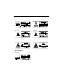


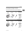
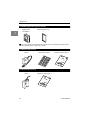

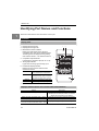

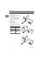
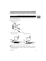


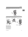


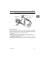

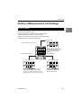

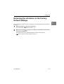


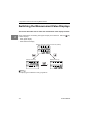
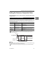
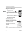


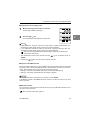

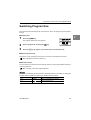


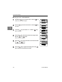
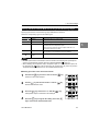

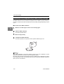


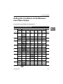


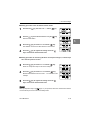

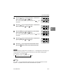
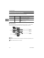


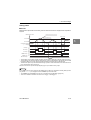

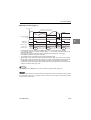


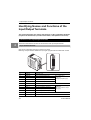

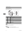

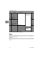
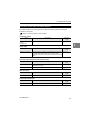
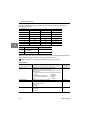

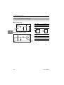
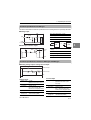

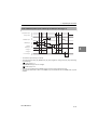

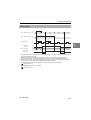
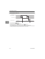


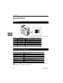


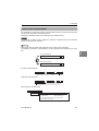
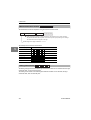


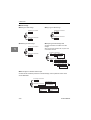


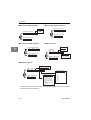

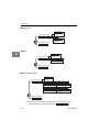

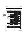
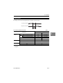


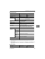


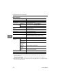
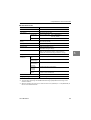


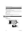


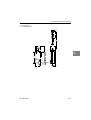


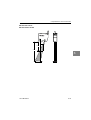


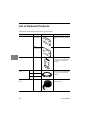


![MFM_NC_7_00 [English]](http://vs1.manualzilla.com/store/data/006337347_1-941bd888a6bb6b638f9564937d1217d4-150x150.png)