1
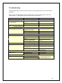
OBE Hydraulic Disc Brake
Installation and Service Manual
Haraka
© copyright 2006-2008
Original Bike Engineering Ltd
www.discobrakes.com
v008
1
Contents
Introduction................................................................................ 3
Definitions .................................................................................. 3
Important Safety Information ....................................................... 4
Installation ................................................................................. 6
Tools Required for Installation .......................................................................6
Fitting the Disc Rotors ..................................................................................6
Fitting the lever and master cylinder...............................................................7
Fitting the Calipers .......................................................................................7
Securing the Hose & Completing the Installation ..............................................8
Bedding In Period ........................................................................ 8
Personal Settings ........................................................................ 9
To Position the Master Cylinder and Lever: ......................................................9
Lever Reach Adjustment .............................................................. 9
Transport of the bicycle................................................................ 9
Service & Maintenance ................................................................10
Brake Pads ................................................................................................ 10
Pad Removal ......................................................................................... 10
Pad Insertion ......................................................................................... 10
Cleaning....................................................................................11
Pistons Pushed Out..................................................................................... 11
Bleeding the System ...................................................................11
Procedure for Bleeding................................................................................ 12
Changing the brake fluid ............................................................................. 13
Hose Changes ............................................................................13
Troubleshooting .........................................................................15
Warranty...................................................................................16
2
Introduction
Congratulations, you have purchased a fully hydraulic disc brake system by Original
Bike Engineering.
This manual contains important information about the safe installation, operation and
maintenance of your disc brake. We urge you to read it carefully, become familiar
with its contents and follow its recommendations to help make your new braking
experience enjoyable and trouble free.
Although relatively little maintenance is required, you should not attempt to carry
out any maintenance procedure until you are thoroughly familiar with the entire set
of procedures. Do not overestimate your technical skill; if in any doubt leave
installation and maintenance to a qualified technician.
Definitions
Warning: These matters must be abided by as there is the possibility of personal
injury to yourself or to others.
Recommendation: It is advisable that these matters are abided by for the safe
installation and maintenance of this brake system.
3
Important Safety Information
Warning: As a serious rider you are aware of the need to practice safety in all
aspects of the sport. This includes service and maintenance practices as well as
riding practices. Before each ride, always check that your brakes are functioning
correctly and check and replace the brake pads if worn. When you ride, always wear
a helmet.
Warning: Installation of the disc brake system or any of its components should be
carried out by a qualified technician with the correct tools. Improper installation
could cause severe or fatal injuries.
Warning: This brake has been designed for use on a single person mountain bike
only. Using it on any other vehicle or for any other purpose will void the warranty
and could cause serious injury.
Warning: Disc brake parts can become extremely hot with use. Always allow parts
to cool before attempting to service your bike. Never touch either the brake rotor or
the brake caliper after braking as this may cause serious burns. Wait for parts to cool
down before doing any work on them.
Warning: When following any of the installation or servicing procedures, make sure
you keep your hands and fingers away from getting caught in the brake rotor.
Failure to do this can result in injury.
Warning: For downhill riding, use a 203mm (8 Inch) brake rotor. Before installing a
203mm brake rotor on your frame or fork, ensure that your frame or fork is capable
of accepting it. Check with your frame or fork manufacturer.
Warning: Using a 160mm (6 Inch) brake rotor for downhill riding may cause the
brake fluid to overheat or even boil and may cause brake failure resulting in serious
injury.
Warning: If you suspect damage to your brakes always get them checked by a
qualified technician
Warning: Before using your brakes for the first time, ensure that the lever you
expect to operate the front brake (right or left) does in fact operate the front brake.
If this is not the case, the hoses should be swapped to avoid unintentional braking,
and potential risk of accidents and injury. Follow the procedure in this manual to
swap the hoses or ask a qualified technician if you are unsure.
Warning: If you notice changing braking points during a ride, you may have air in
your brake system, and you should stop riding. Before using the brake system again,
the brakes must be bled using the procedures outlined in this manual.
Warning: Always protect your brake rotors and brake pads from oils, lubricants,
detergents and soaps. Such substances contaminate the pads and cause a
permanent loss of braking power. Contaminated pads must be replaced before
riding.
4
Warning: If your bike is involved in a crash, you must check your brakes before
riding to ensure they are functioning properly.
•
Check that all components are securely mounted to the handlebar, frame and
fork.
•
Check that the pads are properly seated & retained within the caliper.
•
Check the hose and fittings for any kinks or damage to the reinforcing
braiding.
•
Check the master cylinder body and caliper for damage.
•
Check the hose and fittings for any leaks by activating the lever, holding it,
and checking the hose connections and reservoir cover for leaking brake fluid.
•
Check that the brake operates & bites onto the brake rotor. The lever should
not pull back to the handlebar. If it does see the maintenance section to
rectify it.
Warning: Do not ride your bike unless your wheels move freely without drag. If
your brake rotor is dragging on your pads it will cause premature brake pad wear
and inconsistent braking, which may cause injury. Check that your wheels are
mounted correctly, and all fastenings are correctly tightened. Follow the procedures
in this manual to ensure your brakes are setup correctly.
Recommendation: If using quick release skewers, we recommend the use of steel
skewers only.
Recommendation: We recommend a 3 cross spoke pattern. If the wheel has to be
rebuilt it should be done by a qualified technician.
5
Installation
The following procedures cover the installation of OBE Disc Brakes. A qualified
technician with the correct tools should carry out installation of any disc brake
components. Improper installation could cause severe or fatal injuries.
The disc brake system is supplied fully assembled, containing brake fluid and is
factory bled.
Recommendation: To start with, you should install the brake as supplied without
disconnecting the hose. After using the brake for a while you may want to consider
shortening the hose or routing it through your frame.
Tools Required for Installation
•
•
•
•
•
•
Torx T25 driver
Open-end wrenches; 6mm, 8mm, 10mm
Hose cable cutters
Small flat head and Philips screwdrivers
Allen screwdrivers (Hex keys): 4mm and 5mm
Torque wrench
Fitting the Disc Rotors
Mounting the brake disc rotor to the wheel requires care. The disc rotor is compatible
with International Standard 6 bolt hubs.
Recommendation: We advise the use of thread lock on disc rotor bolts to enhance
the locking and prevent them from unscrewing. Do not use a permanent adhesive.
1. Clean the disc and the hub-mounting surface with isopropyl alcohol.
Warning: Do not use disc brake cleaner.
2. Place the disc on the hub’s mounting surface. Be sure that the arrow on the disc
is pointing in the same direction of the forward wheel rotation.
Warning: Be sure to install the disc rotor with the right side facing upward. Failure
to do so may result in failure of the disc and severe injury. If the disc is the right way
around, you will be able to see the arrow on the disc rotor while tightening the bolts.
The arrow and text on the disc rotor faces outwards from the hub.
3. Use a Torx T25 screwdriver to tighten the disc screws to 5.6 NM (50 in-lbs). For
even tightening, tighten each screw a little at a time and skip alternate screws in the
tightening sequence until all 6 screws are equally tightened.
4. After 12 hours of use, check and re-tighten the disc rotor screws.
Warning: To avoid burns, do not touch the disc immediately after use.
6
Fitting the lever and master cylinder
1. Mount the brake lever to the handlebar with a Torx T25 screwdriver. There is no
need to remove the grips or other controls. Tighten to 3.4 Nm (30 in-lbs).
2. Route the brake hose along the frame/fork to the calipers taking care to avoid
parts of the bike where the hose could be potentially trapped (such as near rear
suspension linkages) or could rub against moving parts (such as the wheels), and
avoiding sharp bends in the hose.
Fitting the Calipers
Warning: When following any of the procedures below, be sure to keep your hands
and fingers from getting caught in the brake rotor. Failure to do so could result in
injury.
1. Remove the wheel, any calipers and adaptors already fitted to the frame or the
fork and check for the following:
•
Make sure that the caliper fitting eyelets on your frame or fork are free of any
paint, powder coating or burrs. The eyelets on a new frame or fork need to be
checked carefully. A newly painted frame or fork will need to have its caliper
fitting eyelets faced. If unsure, have them faced by a qualified technician
using the proper facing tool.
Recommendation: Before fitting a disc brake, have a qualified technician machine
the frame & fork mounts with a facing tool to ensure they are square to the axis of
the hub.
•
Ensure that the brake pads are fully retracted in the caliper. New brakes are
supplied fully retracted with the plastic transport spacer inserted between the
pads. If you need to do this yourself follow the procedure for Pad Removal in
this manual, and then follow the procedure for Pad Insertion.
Recommendation: Do not remove the transport insert until you are ready to install
the wheel.
2. If you have an adaptor to install between the caliper and frame, or caliper and
fork, mount it to the frame or fork using the two (2) M6 adaptor bolts and two (2)
washers supplied with the OBE brake. Leave the bolts loose enough so that the
adaptor can be moved in its slots for alignment.
3. Mount the caliper to the frame or adaptor using the two (2) M6 caliper bolts.
Leave them loose enough so that caliper can be moved for alignment with the brake
rotor.
4. Remove the plastic transport insert from each caliper & re-fit the wheels securely.
Recommendation: Keep the plastic transport insert in a safe place for future use.
Re-insert it between the brake pads whenever you remove the wheels.
7
5. If you have fitted an adaptor, move it until it is just free of the circumference of
the disc rotor. Tighten the adaptor bolts to a torque of 12.4 Nm (110 in-lbs).
6. Centralise the caliper equally on either side of the disc rotor using the shim
washers provided, by fitting them between the caliper / adaptor and the frame or the
fork mounts. This involves some trial and error until the correct positioning is
achieved.
Spin the wheel and check that it spins freely and that the gaps, between the pads
and the disc are equal. If necessary loosen the mounting bolts and repeat steps 5
and 6 until the wheel spins freely and the space between pads and disc are equal on
either side of the disc.
When finished, torque the mounting bolts to 12.4 Nm (110 in-lbs).
Warning: For post mount forks, torque the mounting bolts to 9 Nm (80 in-lbs).
Securing the Hose & Completing the Installation
1. After the caliper and lever have been mounted onto the bike, secure the hose to
the frame using zip ties or hose guides. Check that:
•
The handlebar is unrestricted
•
The hose cannot be trapped in moving parts
•
The hose does not rub on moving parts
•
The hose does not kink at any time
2. With the bike upright on its wheels, squeeze the lever several times (pump) until
the lever feel becomes firm. This will push the pads to their correct position on either
side of the rotor.
3. New pads and rotors will need to be bedded-in by following the instructions in this
manual.
Bedding In Period
To achieve maximum braking power and brake pad longevity, new brake pads and
new rotors need to be bedded-in. Take your bike to a safe place & stop hard 30 to 40
times from about 20 mph (30 kph). During the bedding-in period some noise may
occur.
8
Personal Settings
To Position the Master Cylinder and Lever:
1. Loosen the handlebar clamp screws using a Torx T25 screwdriver
2. Position the Master Cylinder and Lever on the handlebar in your preferred location
and at your preferred angle
3. Tighten the handlebar clamp screws to a torque of 3.4 Nm (30 in-lbs)
Lever Reach Adjustment
In most cases, the factory settings for lever reach adjustment will be suitable for
your bike.
If necessary, use a flat blade screwdriver to adjust the lever reach by turning the
push rod that goes through the lever.
Warning: Do not attempt to force the adjustment screw beyond its limits.
Transport of the bicycle
When transporting a disc brake equipped bicycle, you should keep the following
points in mind:
•
Insert the transport spacer (supplied with the brake) between the brake pads
whenever the wheel is removed from the bike.
•
Never depress the brake lever without the brake pads in place and the wheels
mounted.
•
Make sure that the rotors are not damaged, deformed or contaminated with
lubricants.
•
Do not transport the bike upside-down.
•
For transport in an aircraft, there is no need to empty the fluid from the
hydraulic system, you can leave the brake as it is.
9
Service & Maintenance
Brake Pads
Replace the brake pads when the friction material has worn down to 0.6mm.
Warning: Do not wait until the friction material has worn down to the metal as the
brake rotor will get damaged and the brake may not function causing serious or fatal
injury.
Pad Removal
1. Remove the wheel.
2. Slowly push the brake pads apart by inserting pieces of thin card between
them, until they are far enough apart to remove one brake pad and then the
other.
Warning: Do not use a screwdriver or sharp object to prize the pads apart as this
will ruin the brake pads and they will need to be replaced.
3. Push one of the pads, using its tab on its metal back plate, towards the
middle of the caliper, then pull to disengage the small spring holding it on to a
post in the center of the piston. Remove the pad once it is disengaged from
the post.
4. Repeat for the other pad.
5. When the pads have been removed follow the Pad Insertion procedure.
Pad Insertion
1. Push the caliper pistons back as far as they will go using the boxed end of a
10mm wrench.
Warning: Do not push on the post in the centre of the piston because it will bend
and will need to be replaced.
2. Put the outer pad in first. Note that the pads are different. Use the tab in the
centre of the metal backing plate to push the new pad into place by angling it
and pushing gently until its spring snaps into place.
3. Check the pad is properly locked into place & repeat for the inner pad.
4. Re-install the wheel.
5. With the bike upright, squeeze the lever several times (pump) until the lever
feel becomes firm. This will push the pads to their correct position.
6. New pads will need to be bedded-in by following the instructions in this
manual.
10
Cleaning
Warning: The brake disc rotor and pads should not be cleaned with disc brake
cleaner. Use only isopropyl alcohol.
Pistons Pushed Out
If the brake lever is pulled without the disc rotor or the transport spacer between the
pads, the caliper pistons will be pushed out & the brake pads will be too close
together. This will prevent the re-installation of the wheel (disc rotor), or will prevent
the wheel from spinning freely.
Bleeding the System
Bleeding means pumping new brake fluid into the system to replace the existing fluid
and push out any trapped air and water.
Air trapped in the hydraulic system of the disc brake will decrease the performance
and feel of the brake, making it feel spongy. The air can be removed by bleeding.
If the hose length is shortened, or the hose is detached to route it through the
frame, or the right & left lever’s hoses are swapped due to local convention or
personal preference, and there is loss of brake fluid during the procedure, the brake
will need to be bled.
Warning: If you get brake fluid on the brake pads they are ruined and dangerous to
use. Replace them with new pads. If you get brake fluid on the disc, clean it
thoroughly using isopropyl alcohol. Do not use disc brake cleaner.
Warning: OBE Hydraulic brakes use DOT4 or DOT5.1 brake fluid only. If you use
any other fluid it will cause serious damage to the brake system resulting in brake
failure.
Warning: Only use new, good quality brake fluid. Using poor quality or old brake
fluid will decrease performance and may result in vapour lock.
Warning: Carefully read the instructions that come with the brake fluid.
Warning: Only use new brake fluid that has come from a closed bottle. Always
replace the brake fluid bottle’s cap to prevent contamination. Some DOT fluids
absorb moisture and will deteriorate and spoil.
Warning: Brake fluid will strip paint so wipe any spillage up immediately and clean
the area thoroughly with isopropyl alcohol.
Warning: Discard old brake fluid in a responsible manner and in accordance with
local laws. Do not pollute drains or the environment.
11
Warning: DOT brake fluid can be an irritant. Avoid contact with skin & eyes and do
not ingest. Wear safety glasses when handling brake fluid and bleeding or
maintaining your brakes. Follow the instructions provided with the brake fluid in case
of contact with eyes, skin or if ingested.
Procedure for Bleeding
1. Remove the wheels to prevent contamination of the disc rotors.
2. Remove the brake pads to prevent contamination. Follow the Pad Removal
instructions in this manual.
3. Push the caliper pistons back as far as they will go using the boxed end of a
10mm wrench.
Warning: Do not push on the post in the centre of the piston because it will bend
and will need to be replaced.
4. Insert a spacer between the pistons to prevent them pushing back out during the
bleeding procedure.
5. Loosen the lever handlebar clamp screws using a Torx T25 screwdriver and
reposition the brake lever so that the master cylinder is level and horizontal. Slightly
tighten the screws in this position.
6. Remove the master cylinder cap by removing the 4 allen screws, using a 2mm
allen key. Then remove the rubber diaphragm inside.
7. Place the closed end of a 6mm spanner over the bleed nipple on the brake caliper.
Fit a length of approximately 30cm of clear plastic hose onto the bleed nipple and
put the other end into an empty container to catch the fluid. Ensure that the hose is
a tight fit.
8. Fill the master cylinder reservoir with brake fluid.
9. Open the bleed nipple on the caliper one quarter of a turn.
10. Slowly pull the brake lever to the handlebar and hold.
11. Close the bleed nipple & release the lever. The bleed nipple must be closed
before the lever is released to avoid sucking air into the system.
12. Repeat steps 8, 9 and 10 until no further air is seen coming out of the bleed
nipple. Refill the master cylinder reservoir as required during this procedure.
13. Make sure the pistons are fully pushed back into the caliper. If not, follow step 3
again to push the pistons back.
14. Hang a towel around the master cylinder to soak up any spills, and then fill the
master cylinder reservoir for the last time.
12
15. Replace the rubber diaphragm. The fluid will overflow. Close the bleed nipple and
remove the hose. Wipe away excess fluid from the caliper and lever.
Warning: Do not over-tighten the bleed nipple on the caliper
16. Replace the master cylinder reservoir cap and gently tighten the 4 allen screws
with a 2mm allen key.
Warning: Do not over-tighten the master cylinder reservoir cap allen screws.
17. Replace the pads by following the procedure for Pad Insertion.
18. Check for system leaks.
Changing the brake fluid
For normal use, change the brake fluid every 3 to 4 years. For extreme use, change
the brake fluid every year.
To change the brake fluid, follow the bleeding procedure.
Fill the master cylinder reservoir five times, and pump the fluid through the system
each time.
Hose Changes
Your OBE hydraulic disc brake is supplied fully assembled and factory bled. The hose
length will suit the majority of forks and frames. However you may wish to make
hose changes, for example in the following circumstances:
•
To shorten the hose
•
To detach the hose and route it through the frame
•
To replace a damaged hose
•
To swap right and left brake levers to suit your personal preference or the
normal setup used in your locale
If the following procedure is carried out carefully and correctly there should be no
fluid loss, and there is no need to re-bleed the hydraulic system.
1. Remove the wheels to prevent contamination of the rotors
2. Remove the brake pads to prevent contamination. Follow the Pad Removal
instructions in this manual.
13
3. Push the caliper pistons back as far as they will go using the boxed end of a
10mm wrench. Insert a spacer to keep the pistons apart.
Warning: Do not push on the post in the centre of the piston because it will bend
and will need to be replaced.
4. At the lever, slide off the plastic hose connector shroud and slide it away from the
connector.
5. Unscrew the hose connector fitting using an 8mm open ended wrench and slide it
down the hose.
6. Detach the hose by gently pulling.
Warning: Once separated hold the hose carefully as it contains brake fluid that
could leak out easily.
7. Make the hose change(s). For example:
•
Trim the hose to the desired length using a hose cutter tool to give a clean
square cut.
Warning: Do not shorten the hose to such an extent as to hamper or restrict
handlebar movement.
•
Route the hose through fork or frame guides taking care:
o
To avoid tight bends, which could cause kinks.
o
To avoid routing the hose such that it could get trapped in moving
parts.
o
That the hose does not rub on moving parts such as the wheels.
8. Pull the lever very gently and when a small drop of brake fluid is visible at the end
of the connector, push the hose onto the connector.
9. Slide the connector fitting back into place & tighten.
10. Slide the plastic hose connector shroud back into place.
If replacing the hose due to damage or a leak, the hose can be disconnected from
the caliper in the same way as it is disconnected from the lever.
14
Troubleshooting
The following table provides a quick reference to causes & solutions of most common
problems.
Refer to the relevant section in this manual for the correct procedures to follow for
each solution. A qualified technician should carry out all work.
Symptom
Possible Problem
Solution
Lever pulls right back to
the handlebar
Pads not re-set after a
service
Air in system
Water in system
Pump the lever
New pads or rotor not
bedded in correctly
Disc is dirty
Pad contaminated
Bed in new pads/rotor
Wheel not seated correctly
Caliper not centered over
rotor
Not enough clearance
between pads & rotor
Warped disc
Re-install wheel
Realign caliper
Air in system
Frame or fork mounts out
of alignment
Incorrect fluid used
Bleed system
Face frame/fork mounts
Pads fall out
Damaged piston
Damaged Pads or Spring
Replace piston
Replace Pads
Fluid Leak
Crash damage
Very old seals
For spare parts consult
www.discobrakes.com
… only occurs after long
periods of braking
No braking power
Disc rubbing on pads
Spongy lever feel
Bleed system
Bleed system
Clean disc
Replace pads
Push pistons back into
caliper
Replace disc
Replace seals and
Bleed system
15
Warranty
Original Bike Engineering (OBE) Disc Brakes are warranted for a period of 12 months
from original purchase date, against defects in materials and workmanship.
The warranty only applies to the original owner and a proof of purchase is required.
The product must be returned to OBE before any warranty claim can be processed.
Any product that OBE finds to be defective will be repaired or replaced at the
discretion of OBE. This warranty does not cover bending, damage or breakage that
has resulted or may have resulted from crashes or falls. This warranty does not
cover any damage or defects caused by alterations or modifications of OBE Disc
Brakes or parts thereof, or by normal wear, improper maintenance, damage(s)
caused by the use of other manufacturers’ parts, improper use or abuse of the
product, or failure to follow instructions contained in an instruction manual for OBE
Disc Brakes. Any modifications made by the user will render the warranty null and
void. The cost of normal maintenance, or replacement of service items that are not
defective, shall be paid for by the original purchaser. OBE shall not be held liable for
any indirect, special or consequential damages. This warranty does not affect your
statutory rights.
16