1
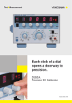
2553A
Precision DC Calibrator
IM 2553A-01EN
1st Edition
Product Registration
Thank you for purchasing YOKOGAWA products.
YOKOGAWA provides registered users with a variety of information and
services.
Please allow us to serve you best by completing the product registration
form accessible from our homepage.
http://tmi.yokogawa.com/
PIM 103-03E
Thank you for purchasing the 2553A Precision DC Calibrator. The 2553A is a DC calibrator that
sources DC voltage, DC current, and resistance. It also sources thermoelectromotive force and
resistance that simulate those of a temperature sensor.
DC voltage
DC current
Resistance
Temperature
sensor
±100 nV to ±32 V
±10 nA to ±120 mA
18 Ω to 400 Ω
Thermocouple:R, S, B, J, T, E, K, N, C, A, user-defined
RTD: Pt100, user-defined
This user’s manual explains the features, operating procedures, and handling precautions of the
2553A. To ensure correct use, please read this manual thoroughly before beginning operation. Keep
this manual in a safe place for quick reference in the event that a question arises.
List of Manuals
The following manuals, including this one, are provided as manuals for the 2553A. Please read all
manuals.
Manual Title
2553A Precision DC Calibrator
User’s Manual
Manual No.
IM 2553A-01EN
Model 2553A Precision DC Calibrator IM 2553A-01Z1
Userʼs Manual
Description
This manual. The manual explains the handling
precautions, features, specifications, communication
interfaces, how to operate the 2553A, and so on.
Document for China
The “EN” and “Z1” in the manual numbers are the language codes.
Contact information of Yokogawa offices worldwide is provided on the following sheet.
Document No.
PIM 113-01Z2
Description
List of worldwide contacts
Notes
• The contents of this manual are subject to change without prior notice as a result of continuing
improvements to the instrument’s performance and functionality. The figures given in this manual
may differ from those that actually appear on your screen.
• Every effort has been made in the preparation of this manual to ensure the accuracy of its
contents. However, should you have any questions or find any errors, please contact your nearest
YOKOGAWA dealer.
• Copying or reproducing all or any part of the contents of this manual without the permission of
YOKOGAWA is strictly prohibited.
• The TCP/IP software of this product and the documents concerning it have been developed/created
by YOKOGAWA based on the BSD Networking Software, Release 1 that has been licensed from
the Regents of the University of California.
Trademarks
• Microsoft, Internet Explorer, MS-DOS, Windows, Windows NT, Windows XP, Windows Vista,
Windows 7, and Windows 8 are either registered trademarks or trademarks of Microsoft Corporation
in the United States and/or other countries.
• Adobe and Acrobat are either registered trademarks or trademarks of Adobe Systems Incorporated.
• In this manual, the ® and TM symbols do not accompany their respective registered trademark or
trademark names.
• Other company and product names are trademarks or registered trademarks of their respective
companies.
Revisions
November 2014 1st Edition
1st Edition: November 2014(YMI)
All Rights Reserved, Copyright © 2014 Yokogawa Meters & Instruments Corporation
IM 2553A-01EN
i
Checking the Contents of the Package
Unpack the box and check the contents before operating the instrument. If the wrong items have been
delivered, if items are missing, or if there is a problem with the appearance of the items, contact your
nearest YOKOGAWA dealer.
2553A
Check that the product that you received is what you ordered by referring to the model name and suffix
code given on the name plate on the rear panel.
MODEL and SUFFIX Codes
Model
2553A
Suffix Code
Specifications
±32 VDC, ± 120 mADC
Version A
Temperature unit Celsius (°C)
Temperature unit Celsius (°C) and Fahrenheit (°F)
UL/CSA standard power cord, maximum rated voltage: 125 V
VDE standard power cord, maximum rated voltage: 250 V
AS standard power cord, maximum rated voltage: 250 V
BS standard power cord, maximum rated voltage: 250 V
GB standard power cord, maximum rated voltage: 250 V
NBR standard power cord, maximum rated voltage: 250 V
-VA
Temperature unit
Power cord*
-UC
-UF
-D
-F
-R
-Q
-H
-N
* Make sure that the attached power cord meets the designated standards of the country and area
that you are using it in.
No. (Instrument number)
When contacting the dealer from which you purchased the instrument, please give them the instrument
number.
Standard Accessories
The instrument is shipped with the following accessories. Make sure that all accessories are present
and undamaged.
Power cord (one cord that matches the suffix code is included)*
UL/CSA standard
A1006WD
D
Measurement lead
366961
VDE standard
A1009WD
AS standard
A1024WD
F
Terminal plug
A2119JT
BS standard
A1054WD
R
Rubber leg cap
A9088ZM
GB standard
A1064WD
Q
Manuals
H
NBR standard
A1088WD
N
IM 2553A-01EN
User’s Manual (this manual)
IM 2553A-92Z1
Document for China
PIM 113-01Z2
List of worldwide contacts
* Make sure that the attached power cord meets the designated standards of the country and area
that you are using it in.
ii
IM 2553A-01EN
Checking the Contents of the Package
Optional Accessories (Sold separately)
The following optional accessories are available for purchase separately.
For information about ordering accessories, contact your nearest YOKOGAWA dealer.
Item
Measurement lead set
Measurement lead set
Measurement lead set
Alligator clip adapter set
Fork terminal adapter set
RJ Sensor
IM 2553A-01EN
Model/Part No.
758933
758917
366961
758922
758921
257875
Min. Q’ty
1 set
1 set
1 set
1 set
1 set
1
Note
Safety terminal cable. Length: 1 m.
Safety terminal cable. Length: 0.75 m.
1:1 Banana-alligator clip cable. Length: 1.2 m.
Safety terminal-to-alligator clip adapter. Rating: 300 V.
Safety terminal-to-fork terminal adapter
For reference junction compensation. Pt100 sensor.
iii
Safety Precautions
This instrument is an IEC safety class I instrument (provided with a terminal for protective earth
grounding).
The general safety precautions described herein must be observed during all phases of operation.
If the instrument is used in a manner not specified in this manual, the protection provided by the
instrument may be impaired. YOKOGAWA assumes no liability for the customer’s failure to comply
with these requirements.
The following symbols are used on this instrument.
Warning: handle with care. Refer to the user’s manual or service manual. This symbol appears
on dangerous locations on the meter which require special instructions for proper handling
or use. The same symbol appears in the corresponding place in the manual to identify those
instructions.
Ground (earth) or functional ground terminal (do not use this terminal as a protective ground
terminal)
Alternating current
On (power)
Off (power)
Power-on state
Power-off state
French
Avertissement : À manipuler délicatement. Toujours se reporter aux manuels d'utilisation et
d'entretien. Ce symbole a été apposé aux endroits dangereux de l'instrument pour lesquels des
consignes spéciales d'utilisation ou de manipulation ont été émises. Le même symbole apparaît
à l'endroit correspondant du manuel pour identifier les consignes qui s'y rapportent.
Borne de terre ou borne de terre fonctionnelle (ne pas utiliser cette borne comme prise de
terre)
Courant alternatif
Marche (alimentation)
Arrêt (alimentation)
Marche
Arrêt
iv
IM 2553A-01EN
Safety Precautions
Failure to comply with the precautions below could lead to injury
or death or damage to the instrument.
WARNING
Use the Instrument Only for Its Intended Purpose
The 2553A is a DC calibrator that sources DC voltage, DC current, and resistance. It also
sources thermoelectromotive force and resistance that simulate those of a temperature
sensor. Use the 2553A only for these purposes.
Check the Physical Appearance
Do not use the instrument if there is a problem with its physical appearance.
Power supply
Make sure that the power supply voltage matches the instrument's rated supply voltage and
that it does not exceed the maximum voltage range specified for the power cord.
Use the Correct Power Cord and Plug
To prevent electric shock and fire, be sure to use a power cord provided by YOKOGAWA.
The main power plug must be plugged into an outlet with a protective earth terminal. Do not
invalidate this protection by using an extension cord without protective earth grounding.
Additionally, do not use the power cord supplied with this instrument with another instrument.
Connect the Protective Grounding Terminal
Make sure to connect the protective earth to prevent electric shock before turning on the
power. The power cord that comes with the instrument is a three-prong type power cord.
Connect the power cord to a properly grounded three-prong outlet.
Do Not Impair the Protective Grounding
Never cut off the internal or external protective earth wire or disconnect the wiring of the
protective earth terminal. Doing so may result in electric shock or damage to the instrument.
Do Not Operate with Defective Protective Grounding or Fuses
Do not operate the instrument if the protective earth or fuse might be defective. Check the
grounding and the fuse before operating the instrument.
Do Not Operate in an Explosive Atmosphere
Do not operate the instrument in the presence of flammable gases or vapors. Doing so is
extremely dangerous.
Do Not Remove Covers or Disassemble or Alter the Instrument
Only qualified YOKOGAWA personnel may remove the covers and disassemble or alter the
instrument. The inside of the instrument is dangerous because parts of it have high voltages.
Ground the Instrument before Making External Connections
Securely connect the protective grounding before connecting to the target device or to an
external control unit. Before touching the target device, turn off this instrument and check that
there is no voltage or current being output.
IM 2553A-01EN
v
Safety Precautions
Measurement Category
The measurement category of the 2553A terminals is Other (O). Do not use it for main power
supply circuits or circuits that fall under Measurement Categories II, III, and IV.
Install or Use the Instrument in Appropriate Locations
• Do not install the instrument outdoors or in locations subject to rain or water. Or, use the
instrument in such locations.
• Install the instrument so that you can immediately remove the power cord if an abnormal or
dangerous condition occurs.
Wire Cables Correctly
This instrument sources voltage and current. Not wiring the devices correctly may damage the
instrument or the target device. Be careful when you wire the cables, and be sure to check the
following points.
Before output (before turning on the output), check that:
• Cables have been wired to the instrument’s output terminals correctly.
• Cables have been wired to the target device correctly.
Check that there are no short circuits between terminals or between the cables connected
to the terminals.
• The cables are fastened firmly to the terminals.
• There no problems with the terminals, such as the presence of foreign substances.
During output (do not touch the terminals or the connected cables when this instrument is on),
check that:
• There no problems with the terminals, such as the presence of foreign substances.
• The terminals are not abnormally hot.
After output (immediately after the output is turned off)
After you output a voltage or current, voltage may remain for some time even after you turn
the output off. Do not touch the terminals immediately after you turn the output off. The
amount of time that voltage remains varies depending on the target device.
CAUTION
Operating Environment Limitations
This product is a Class A (for industrial environment) product. Operation of this product in a
residential area may cause radio interference in which case the user will be required to correct
the interference.
vi
IM 2553A-01EN
Safety Precautions
French
AVERTISSEMENT
Utiliser l'instrument aux seules fins pour lesquelles il est prévu
Le 2553A est un calibreur c.c. qui émet de la tension c.c., du courant c.c. et de la résistance.
Il émet également une force thermo-électromotive et une résistance qui stimulent celles des
capteurs de température. Utiliser le 2553A à ces fins exclusives.
Inspecter l'apparence physique
Ne pas utiliser l'instrument si son intégrité physique semble être compromise.
Vérifier l'alimentation
Avant de brancher le cordon d'alimentation, vérifier que la tension source correspond à la
tension d'alimentation nominale du 2553A et qu'elle est compatible avec la tension nominale
maximale du cordon d'alimentation.
Utiliser le cordon d'alimentation et la fiche adaptés
Pour éviter tout risque de choc électrique ou d'incendie, toujours utiliser le cordon
d'alimentation fourni par YOKOGAWA. La fiche doit être branchée sur une prise secteur
raccordée à la terre. En cas d'utilisation d'une rallonge, celle-ci doit être impérativement reliée
à la terre. Ne pas utiliser le cordon d'alimentation fourni avec l'instrument pour tout autre
appareil.
Brancher la prise de terre
Avant de mettre l'instrument sous tension, penser à brancher la prise de terre pour éviter tout
choc électrique. Le cordon d'alimentation livré avec l'instrument est doté de trois broches.
Brancher le cordon d'alimentation sur une prise de courant à trois plots et mise à la terre.
Ne pas entraver la mise à la terre de protection
Ne jamais neutraliser le fil de terre interne ou externe, ni débrancher la borne de mise à la
terre. Cela pourrait entraîner un choc électrique ou endommager l'instrument.
Ne pas utiliser avec un conducteur de terre ou un fusible défectueux
Ne pas utiliser l'instrument si le conducteur de terre ou le fusible est défectueux. Vérifier le
conducteur de terre et le fusible avant d'utiliser l'instrument.
Ne pas utiliser dans un environnement explosif
Ne pas utiliser l'instrument en présence de gaz ou de vapeurs inflammables. Cela pourrait
être extrêmement dangereux.
Ne pas retirer le capot, ni démonter ou modifier l'instrument
Seul le personnel YOKOGAWA qualifié est habilité à retirer le capot et à démonter ou modifier
l'instrument. Certains composants à l'intérieur de l'instrument sont à haute tension et par
conséquent, représentent un danger.
Relier l'instrument à la terre avant de le brancher sur des connexions externes
Toujours relier l'instrument à la terre avant de le brancher aux appareils à mesurer ou à une
commande externe. Avant de toucher un circuit, mettre l'instrument hors tension et vérifier
l'absence de tension. Pour éviter tout risque de choc électrique, brancher la terre de la sonde
et du connecteur d'entrée sur la terre de l'appareil à mesurer.
IM 2553A-01EN
vii
Safety Precautions
Catégorie de mesure
La catégorie de mesure des terminaux d'entrée de signal du 2553A est Autre (O). Ne pas
l'utiliser pour mesurer l'alimentation électrique, ni pour les catégories de mesure II, III et IV.
Installer et utiliser l'instrument aux emplacements appropriés
• Ne pas installer, ni utiliser l'instrument à l'extérieur ou dans des lieux exposés à la pluie ou
à l'eau.
• Installer l'instrument de manière à pourvoir immédiatement le débrancher du secteur en
cas de fonctionnement anormal ou dangereux.
Vérifier le câblage
Cet instrument émet de la tension et du courant. Un câblage inapproprié de cet appareil peut
endommager l'instrument ou l'appareil cible. Toujours brancher les câbles correctement et
vérifier les points suivants.
Avant le sortie (avant la mise sous tension), vérifier que :
• Les câbles ont été correctement branchés sur les bornes de sortie de l'instrument.
• Les câbles ont été correctement branchés sur l'appareil cible.
Vérifier qu'il n'y a pas de court-circuit entre les bornes ou entre les câbles branchés sur les
bornes.
• Les câbles sont fermement vissés sur les bornes.
• Les bornes ne présentent aucune anomalie, telle la présence de corps étrangers.
Pendant la sortie (ne pas toucher les bornes ni les câbles branchés lorsque l'instrument est
sous tension), vérifier que :
• Les bornes ne présentent aucune anomalie, telle la présence de corps étrangers.
• Les bornes ne chauffent pas anormalement.
Après la sortie (tout de suite après la mise hors tension)
Après avoir émis une tension ou un courant élevé, une tension résiduelle peut rester un
certain temps dans l'appareil mesuré, même après sa mise hors tension. Ne pas toucher
les bornes tout de suite après avoir mis l'appareil hors tension. La durée pendant laquelle
la tension résiduelle reste dans l'appareil varie selon les appareils.
ATTENTION
Limitations relatives à l'environnement opérationnel
Ce produit est un produit de classe A (pour environnements industriels). L'utilisation de ce
produit dans un zone résidentielle peut entraîner une interférence radio que l'utilisateur sera
tenu de rectifier.
viii
IM 2553A-01EN
Sales in Each Country or Region
Waste Electrical and Electronic Equipment
Waste Electrical and Electronic Equipment (WEEE), DIRECTIVE 2012/19/EU
(This directive is valid only in the EU.)
This product complies with the WEEE Directive (2012/19/EU) marking requirement. This
marking indicates that you must not discard this electrical/electronic product in domestic
household waste.
Product Category
With reference to the equipment types in the WEEE directive Annex I, this product is classified
as a “Monitoring and control instruments” product.
Do not dispose in domestic household waste. When disposing products in the EU, contact your
local Yokogawa Europe B. V. office.
Authorized Representative in the EEA
Yokogawa Europe B. V. is the authorized representative of Yokogawa Meters & Instruments
Corporation in the EEA for this product. To contact Yokogawa Europe B. V., see the separate list of
worldwide contacts, PIM 113-01Z2.
IM 2553A-01EN
ix
Conventions Used in This Manual
Notes
The notes and cautions in this manual are categorized using the following symbols.
Improper handling or use can lead to injury to the user or damage to the
instrument. This symbol appears on the instrument to indicate that the user must
refer to the user’s manual for special instructions. The same symbol appears in
the corresponding place in the user's manual to identify those instructions. In the
user’s manual, the symbol is used in conjunction with the word “WARNING” or
“CAUTION.”
WARNING
Calls attention to actions or conditions that could cause serious or fatal injury to
the user, and precautions that can be taken to prevent such occurrences.
CAUTION
Calls attention to actions or conditions that could cause light injury to the user
or cause damage to the instrument or user’s data, and precautions that can be
taken to prevent such occurrences.
French
AVERTISSEMENT
ATTENTION
Note
x
Attire l’attention sur des gestes ou des conditions susceptibles
de provoquer des blessures graves (voire mortelles), et sur les
précautions de sécurité pouvant prévenir de tels accidents.
Attire l’attention sur des gestes ou des conditions susceptibles de
provoquer des blessures légères ou d’endommager l’instrument ou les
données de l’utilisateur, et sur les précautions de sécurité susceptibles
de prévenir de tels accidents.
Calls attention to information that is important for the proper operation of the
instrument.
IM 2553A-01EN
Conventions Used in This Manual
Characters That Appear on the 7-Segment LED
Because this instrument uses a 7-segment LED display, numbers, letters, and mathematical symbols
are displayed using special characters. For details, see section 1.2, “Digital Numbers and Characters.”
Symbols and Conventions Used in Procedural Explanations
The contents of the procedural explanations are indicated using the following symbols.
Procedure
Carry out the procedure according to the step numbers. All procedures are
written under the assumption that you are starting operation at the beginning
of the procedure, so you may not need to carry out all the steps in a procedure
when you are changing the settings.
Explanation This section describes the setup items and the limitations regarding the
procedures. It may not give a detailed explanation of the feature. For a detailed
explanation of the feature, see chapter 2.
<<Command Mnemonic>>
Indicates a communication command that corresponds to some of the features described on the
procedural explanation page.
Characters and Terminology Used in Procedural Explanations
Dial and Switches
Bold characters used in the procedural explanations indicate dials and switches on the panel.
IM 2553A-01EN
xi
Contents
List of Manuals....................................................................................................................................i
Checking the Contents of the Package............................................................................................. ii
Safety Precautions............................................................................................................................ iv
Sales in Each Country or Region...................................................................................................... ix
Conventions Used in This Manual.....................................................................................................x
Chapter 1 Names and Functions of Parts
1.1Panels............................................................................................................................... 1-1
1.2
Digital Numbers and Characters....................................................................................... 1-3
Chapter 2 Features
2.1
2.2
2.3
DC Voltage, DC Current, and Resistance Sourcing.......................................................... 2-1
Temperature-Sensor-Simulation Thermoelectromotive-Force and Resistance Sourcing. 2-3
Other Features.................................................................................................................. 2-5
Chapter 3 Preparation
3.1
3.2
3.3
3.4
3.5
3.6
Handling Precautions........................................................................................................ 3-1
Installing the 2553A........................................................................................................... 3-3
Connecting to the Power Supply....................................................................................... 3-6
Turning On and Off the Power Switch............................................................................... 3-8
Wiring Precautions.......................................................................................................... 3-10
Connecting Wires............................................................................................................ 3-12
Chapter 4 SETUP Menu
4.1
4.2
SETUP Menu Tree Structure............................................................................................. 4-1
Using the SETUP Menu.................................................................................................... 4-3
Chapter 5 Voltage, Current, and Resistance Sourcing
5.1
5.2
5.3
Selecting the Voltage, Current, or Resistance Range....................................................... 5-1
Specifying the Output Setting and Polarity........................................................................ 5-2
Turning the Output On and Off.......................................................................................... 5-4
Chapter 6 Temperature-Sensor-Simulation Thermoelectromotive-Force and
Resistance Sourcing
6.1
6.2
6.3
6.4
6.5
6.6
Selecting Thermocouples and RTDs................................................................................. 6-1
Setting the Temperature.................................................................................................... 6-3
Turning the Output On and Off.......................................................................................... 6-5
Writing User-Defined Data................................................................................................ 6-6
Setting Reference Junction Compensation......................................................................6-11
Selecting the Temperature Unit....................................................................................... 6-15
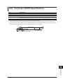
Chapter 7 GP-IB Interface
7.1
7.2
7.3
7.4
xii
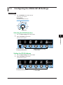
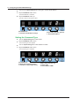
GP-IB Interface Features and Specifications.................................................................... 7-1
Connecting through the GP-IB Interface........................................................................... 7-3
Configuring the 2553A GP-IB Settings.............................................................................. 7-5
Responses to Interface Messages.................................................................................... 7-8
IM 2553A-01EN
Contents
Chapter 8 Ethernet Interface
8.1
8.2
8.3
Ethernet Interface Features and Specifications................................................................ 8-1
Connecting to the Ethernet Interface................................................................................. 8-2
Configuring the 2553A Ethernet Settings.......................................................................... 8-3
Chapter 9 USB Interface
9.1
9.2
9.3
USB Interface Features and Specifications....................................................................... 9-1
Connecting through the USB Interface.............................................................................. 9-2
Configuring the 2553A USB Interface............................................................................... 9-3
Chapter 10 Programming Overview
10.1Messages........................................................................................................................ 10-1
10.2Commands...................................................................................................................... 10-3
10.3Responses...................................................................................................................... 10-5
10.4 Data................................................................................................................................. 10-6
10.5 Synchronization with the Controller................................................................................. 10-8
Chapter 11 Commands
11.1
11.2
11.3
11.4
11.5
11.6
11.7
List of Commands............................................................................................................11-1
COMMunicate Group.......................................................................................................11-3
OUTPut Group.................................................................................................................11-4
SOURce Group................................................................................................................11-5
STATus Group................................................................................................................11-10
SYSTem Group..............................................................................................................11-11
Common Command Group............................................................................................11-13
1
2
3
4
5
6
7
8
Chapter 12 Status Reports
12.1
12.2
12.3
12.4
12.5
About Status Reports...................................................................................................... 12-1
Status Byte...................................................................................................................... 12-3
Standard Event Register................................................................................................. 12-4
Extended Event Register................................................................................................. 12-5
Output and Error Queues................................................................................................ 12-6
9
10
Chapter 13 Troubleshooting, Maintenance, and Inspection
13.1Troubleshooting............................................................................................................... 13-1
13.2 Error Indication................................................................................................................ 13-2
13.3 Error Code Descriptions and Corrective Actions............................................................. 13-4
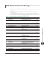
13.4 Communication Error Messages..................................................................................... 13-5
13.5 Displaying the Error Log.................................................................................................. 13-8
13.6 Instrument Error Detection and Clearance.................................................................... 13-10
13.7Self-Test.........................................................................................................................13-11
13.8 Initializing the Settings................................................................................................... 13-12
13.9 Displaying the Product Information............................................................................... 13-13
13.10 Calibration and Adjustment........................................................................................... 13-15
11
12
13
14
App
IM 2553A-01EN
xiii
Index
Contents
Chapter 14 Specifications
14.1
14.2
14.3
14.4
14.5
14.6
14.7
Appendix
Source Section................................................................................................................ 14-1
Functions......................................................................................................................... 14-5
External Input.................................................................................................................. 14-6
Computer Interface.......................................................................................................... 14-6
General Specifications.................................................................................................... 14-7
RJ Sensor 257875 Specifications................................................................................... 14-9
External Dimensions..................................................................................................... 14-10
Appendix 1
Appendix 2
Appendix 3
Appendix 4
Appendix 5
Appendix 6
Appendix 7
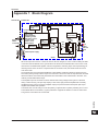
Block Diagram..................................................................................................... App-1
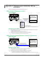
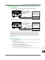
Thermocouple Calibration Wiring Examples....................................................... App-2
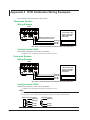
RTD Calibration Wiring Examples....................................................................... App-4
User Definitions of Thermocouples and RTDs.................................................... App-5
List of Default Settings and Settings That Are Saved......................................... App-9
About the IEEE 488.2-1992 Standard............................................................... App-10
ASCII Character Codes..................................................................................... App-11
Index
xiv
IM 2553A-01EN
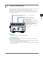
Chapter 1
1.1
Names and Functions of Parts
Panels
1
Names and Functions of Parts
2
Front Panel
Handle → sec. 3.1, 3.2
POLARITY switch
Flip the lever up or down to set the
polarity.
→ sec. 5.2, 6.2
While in the SETUP menu, this
confirms or cancels the setting.
→ sec. 4.2
Output setting display
Displays the value set with the output setting dials. 5.5-digit
7-segment LEDs are used.
→ sec. 5.2, 6.2
3
While in the SETUP menu, these display the menus at different
hierarchical levels. At levels where a value is set or displayed,
these display the value.
→ ch. 4, sec. 6.5, 6.6, 7.3, 8.3, 9.3, 13.5, 13.7 to 13.9
Polarity display
Displays the polarity set with the
POLARITY switch
→ sec. 5.2, 6.2
4
Unit display
Displays the unit of the output setting. 5×7
dot matrix LEDs are used.
→ sec. 5.2, 6.2
5
Displays the auxiliary information of a
SETUP menu when available
→ sec. 4.2
6
RJC indicators
Indicates the current RJC mode.
→ sec. 6.5
7
REMOTE indicator
Illuminates when the 2553A is in
remote mode (controlled through
communications)
→ sec. 7.1, 8.1, 9.1
Bottom legs
→ sec. 3.2
Power switch
Turns the power on and off
→ sec. 3.4
TEMPERATURE dial
Switches the thermocouple
or RTD type and the RJC
mode.
→ sec. 6.1, 6.4, 6.5
RANGE dial
Switches the voltage, current,
resistance, and temperature
ranges.
→ sec. 5.1, 6.1
When SETUP is selected, a
SETUP menu appears.
→ ch. 4, sec. 6.5, 6.6, 7.3, 8.3,
9.3, 13.5, 13.7 to 13.9
Output setting dials
Used to set the value of the digit immediately above each dial.
Carrying over and borrowing occur automatically within the
selectable range. From the left, the dials are the 1st, 2nd, 3rd,
4th, and 5th dials. The 1st dial is used also to set the most
significant digit (the next left digit) to 1.
→ sec. 5.2, 6.2, 6.5
8
ON indicator
Illuminates when voltage,
current, resistance, or temperature (thermocouple or RTD) is
being generated
→ sec. 5.3, 6.3
OFF indicator
Illuminates when nothing is being
generated
→ sec. 5.3, 6.3
OUTPUT switch
Flip the lever up to turn the output
on. Flip down to turn it off.
→ sec. 5.3, 6.3
9
10
11
Flipping this lever down in remote
mode causes the 2553A to switch
to local mode.
→ sec. 7.1, 8.1, 9.1
12
Output terminals
Connect measurement leads to these terminals.
→ sec. 3.5, 3.6
13
When the polarity is set to positive, the red
terminal is positive. When the polarity is set to
negative, the red terminal is negative.
14
While in the SETUP menu, these are used to select the menus
at different hierarchical levels. At levels where a value is set or
displayed, these are used to set the value.
→ ch. 4, sec. 6.5, 6.6, 7.3, 8.3, 9.3, 13.5, 13.7 to 13.9
IM 2553A-01EN
App
1-1
Index
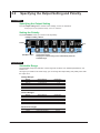
1.1 Panels
Rear Panel
Power inlet
Connect the power cord.
→ sec. 3.3
Nameplate
GP-IB port
Used when controlling the 2553A
remotely from a PC through the GP-IB
interface
→ ch. 7
External RJ sensor
input terminal
Used to connect an
external RJ sensor
→ sec. 3.6, 6.5
Ethernet port (100BASE-TX/10BASE-T)
Used when controlling the 2553A remotely from a PC through the Ethernet
interface
→ ch. 8
USB port (type B)
Used when writing user-defined files for thermocouple and RTD temperature output from a
PC to the 2553A (USB mass storage)
→ sec. 6.4
Used when controlling the 2553A remotely from a PC through the USB interface (USB-TMC)
→ ch. 9
Top and Bottom Panels
Top panel
Bottom panel
Vent holes
Do not block the vent holes
when installing the 2553A.
→ sec. 3.2
Rear legs
→ sec. 3.2
1-2
IM 2553A-01EN
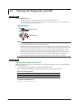
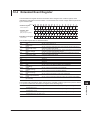
1.2
Digital Numbers and Characters
1
Names and Functions of Parts
Because this instrument uses a 7-segment LED display to show output settings, special characters are
used to display numbers, letters, and mathematical symbols as shown below. Some of the characters
shown below are not used by this instrument.
2
3
^(power)
Lowercase c
4
5
Lowercase h
6
7
8
9
10
11
12
13
14
App
IM 2553A-01EN
1-3
Index
Chapter 2
Features
2.1
DC Voltage, DC Current, and Resistance
Sourcing
1
2
Features
The 2553A is a DC calibrator that sources DC voltage, DC current, and resistance. It also sources
thermoelectromotive force and resistance that simulate those of a temperature sensor. This section
describes the DC voltage, DC current, and resistance sourcing features. For a description of the
thermoelectromotive-force and resistance sourcing features, see section 2.2.
3
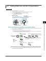
Source and Sink
The 2553A can not only source current but also sink current.1, 2 Sinking is possible regardless of
whether the source voltage is positive or negative.
4
Current
+
Sink
5
Source
+
−
Source
Voltage
6
Sink
−
1 By absorbing the current from a voltage source such as a distributor, the 2553A can simulate a load, like a
two-wire transmitter.
2 Excludes the 10 mV range. When using the 10 mV range, do not apply external voltage or current.
7
8
DC Voltage Sourcing
The source range and output current for each voltage range are shown below. The 2553A outputs
the specified DC voltage, within the range limited by the maximum output current, to the load circuit
connected to the output terminals.
9
Current
Sink
(excluding
the 10 mV
range)
−32 V
−12 V
Approx. 120 mA
Source
Approx. 30 mA
12 V 32 V
Range
10 mV
100 mV
1V
10 V
30 V
Source Range
±12.0000 mV
±120.000 mV
±1.20000 V
±12.0000 V
±32.000 V
10
Maximum Output Current
—1
10 mA or higher2
Approx. 120 mA
Approx. 120 mA
Approx. 30 mA
11
Voltage 1 Since a voltage divider is used in the 10 mV range, the output resistance is
approximately 1 Ω. It is not suitable for connecting to a low-impedance load
Approx. –30 mA
that requires current to flow through. The output voltage will drop if such a
load is connected. Connect a high-impedance load, a load that is sufficiently
Sink
Source
(excluding the
larger than the output resistance. When using the 10 mV range, do not apply
10 mV range)
external voltage or current. Doing so may damage the voltage divider.
2 In the 100 mV range, the output voltage may drop significantly when the
Approx. –120 mA
output current exceeds 10 mA. Connect a load that will not cause the output
current to exceed 10 mA.
The maximum sink current is the same as the maximum output current of each range except for the 10 mV range.
: Immediately after sinking current in this region, errors exceeding the accuracy specifications may occur
due to the increased temperature inside the 2553A.
12
13
14
App
IM 2553A-01EN
2-1
Index
2.1 DC Voltage, DC Current, and Resistance Sourcing
DC Current Sourcing
The source range and output voltage for each current range are shown below. The 2553A outputs
the specified DC current, within the range limited by the maximum output voltage, to the load circuit
connected to the output terminals.
1 mA, 10 mA, or 100 mA range
Voltage
Sink
−120 mA
Source
Approx. 15 V
−32 mA 32 mA
120 mA
Current
Approx. –15 V
Sink
Source
Range
1 mA
10 mA
30 mA
100 mA
30 mA range
Voltage
Approx. 30 V
Sink
−32 mA
Source
Source
32 mA
Current
Source Range
±1.20000 mA
±12.0000 mA
±32.000 mA
±120.000 mA
Maximum Output Voltage
Approx. 15 V
Approx. 15 V
Approx. 30 V
Approx. 15 V
The sink current range is the same as the source range of each range.
: Immediately after sinking current in this region, errors
exceeding the accuracy specifications may occur due to
the increased temperature inside the 2553A.
Sink
Approx. –30 V
Resistance Sourcing
The 2553A sources simulation resistance R (= V/I) by outputting from its output terminals voltage V,
which is defined as R×I, where R is the specified resistance and I the excitation current for measuring
resistance. The excitation current is supplied to the 2553A output terminals from the device to be
calibrated.* For example, if the excitation current is 1 mA and the specified resistance is 100 Ω, the
2553A outputs 0.1 V.
The source range and excitation current for the resistance are shown below.
* Resistance measuring instrument, RTD thermometer, etc.
Resistance
400 Ω
Source
18 Ω
0.5 mA
2 mA
Range
400 Ω
Source Range
18.00 Ω to 400.00 Ω
Excitation current
0.5 mA to 2 mA
Excitation current
Turning the Output On and Off
The specified voltage, current, or resistance output and current sink can be turned on and off.
•ON
The specified voltage, current, or resistance is output from the output terminals. If the output is
outside the selectable range, the output cannot be turned on. In current sink mode, sinking is
performed.
•OFF
No output is produced. If you change the range or if the overload protection function is activated,
the output automatically turns off.
2-2
IM 2553A-01EN
2.2Temperature-Sensor-Simulation
Thermoelectromotive-Force and Resistance
Sourcing
1
2
Features
For the specified temperature, the 2553A sources thermoelectromotive force and resistance that
simulate those of a thermocouple and RTD.
3
Thermocouple
The 2553A outputs from its output terminals the thermoelectromotive force (voltage) that corresponds
to the specified temperature according to the selected thermocouple type. The available thermocouple
types are R through A as defined by IEC and JIS standards and are listed in the following table. It is
also possible to user-define the relationship between temperature and thermoelectromotive force and
output thermoelectromotive force according to the definition.
* Since a voltage divider is used to set the different thermocouple ranges, the output resistance is
approximately 1 Ω. It is not suitable for connecting to a low-impedance load that requires current to flow
through. The output voltage will drop if such a load is connected. Connect a high-impedance load, a
load that is sufficiently larger than the output resistance. When using thermocouple ranges, do not apply
external voltage or current. Doing so may damage the voltage divider.
Type
R
S
B
J
T
E
K
N
C
A
TC USER
(user-defined)
Source Range
-50°C to +1768°C
-50°C to +1768°C
0°C to +1820°C
-210°C to +1200°C
-270°C to +400°C
-270°C to +1000°C
-270°C to +1300°C
-270°C to +1300°C
0°C to +2315°C
0°C to +2500°C
5
6
7
8
9
-9999.9°C to +9999.9°C
10
RJC Mode
The RJC mode can be set to auto, internal, or manual input. The 2553A corrects the sourced
thermoelectromotive force (RJC) according to the selected mode. It is also possible to source
thermoelectromotive force without correction.
•Auto
• When the 2553A detects that an RJ sensor is connected to the external RJ sensor input
terminal on the rear panel, the 2553A sources thermoelectromotive force that is corrected using
the temperature measured by the external RJ sensor. The 2553A can measure the terminal
temperature of the device to be calibrated that is connected to the 2553A using an RJ sensor
and source thermoelectromotive force that is corrected using the measured temperature.
• If an RJ sensor is not connected to the 2553A or is not detected, the 2553A applies its internal
RJC.
• RJ sensors 257875 are sold separately as accessories. An RTD Pt100 can also be used as an
RJ sensor.
•Internal
The 2553A sources thermoelectromotive force that is corrected using the temperature of its output
terminals.
IM 2553A-01EN
4
2-3
11
12
13
14
App
Index
2.2 Temperature-Sensor-Simulation Thermoelectromotive-Force and Resistance Sourcing
• Manual input
The 2553A sources thermoelectromotive force that is corrected using the manually input
temperature.
If you do not want to apply correction (not use the RJC function), you set the temperature to 0°C.
* In a thermocouple temperature measurement, the temperature is measured from the thermoelectromotive
force that is produced due to the temperature difference between the measurement point and the
other contact point. If the other contact point is 0°C, the temperature at the measurement point can be
found straight from the thermoelectromotive force. Normally, the other contact point is a terminal on a
measuring instrument, so the temperature of that terminal is measured and used for correcting the actual
measurement. This is called reference junction compensation.
RTD
The 2553A outputs from its output terminals the resistance of an RTD Pt100 that corresponds to the
specified temperature. The 2553A supports Pt100, which is defined by IEC and JIS standards. It is also
possible to user-define the relationship between temperature and resistance and output resistance
according to the definition.
Type
Pt100
RTD USER
(user-defined)
Source Range
-200.0°C to +850.0°C
-9999.9°C to +9999.9°C
Turning the Output On and Off
The output of a thermoelectromotive force or resistance that corresponds to the specified temperature
can be turned on and off.
•ON
Thermoelectromotive force or resistance is output from the output terminals. If the output is outside
the selectable range, the output cannot be turned on.
•OFF
No output is produced. If you change the thermocouple or RTD type, the output automatically turns
off.
User Definition
You can define (user-define) any thermoelectromotive force and resistance that simulate those of
thermocouples or RTDs and then source thermoelectromotive force and resistance according to the
definitions. User-defined data is created by specifying coefficients of polynomials for each temperature
range. The data that you create are written to the 2553A in the following manner.
• Write the user-defined data saved in a file to the 2553A using the USB mass storage feature.
• Transmit the user-defined data for each temperature range using communication commands. The
transmitted data is written to the 2553A.
You can assign a type character to distinguish a user definition from other user definitions. The type
character is displayed as the second character on the dot matrix LEDs for displaying the unit when a
user-defined thermoelectromotive-force or resistance source is selected.
For the user-defined data syntax and setup procedure, see appendix 4.
Temperature Unit
If the suffix code is -UC, the temperature unit is Celsius (°C). If the suffix code is -UF, you can select
Celsius (°C) or Fahrenheit (°F). You use the SETUP menu to select it.
2-4
IM 2553A-01EN
2.3
Other Features
1
2
Error Log Display
Initialization
You can initialize the 2553A settings to their factory defaults. You use the SETUP menu to do so.
Communication settings and a portion of other settings are not initialized. For details on the items that
are initialized, see appendix 5.
Features
The error log keeps a record of error codes that occur in communication and self-tests while the 2553A
is on. You use the SETUP menu to display the error log. The error log is cleared when the power is
turned off.
3
4
5
Displaying the Product Information
The firmware version, serial number, and the like can be displayed. You use the SETUP menu to
display them.
•Firmware version
• Logic program version
• Boot program version
• Serial number (instrument number)
6
7
8
9
10
11
12
13
14
App
IM 2553A-01EN
2-5
Index
Chapter 3
3.1
Preparation
Handling Precautions
1
2
Safety Precautions
If you are using the 2553A for the first time, make sure to read “Safety Precautions,” on pages iv and
vi.
Do not remove the case from the instrument. Some parts of the instrument use high voltages and
are extremely dangerous. For internal inspection and adjustment, contact your nearest YOKOGAWA
dealer.
Preparation
Do Not Remove the Case
3
Unplug If Abnormal Behavior Occurs
5
If you notice smoke or unusual odors coming from the instrument, immediately turn off the power and
unplug the power cord. Also, turn off the power to the target device that are connected to the output
terminals. Then, contact your nearest YOKOGAWA dealer.
4
6
Do Not Damage the Power Cord
Nothing should be placed on top of the power cord. The power cord should also be kept away from
any heat sources. When removing the plug from the power outlet, do not pull on the cord. Pull from the
plug. If the power cord is damaged, purchase a replacement with the same part number as the one
indicated on page ii.
7
8
Correct the Problem If Output Is Automatically Turned Off
If an abnormality is detected in the internal circuit due to a voltage or current overloading, voltage or
current output oscillation, and so on, the 2553A will automatically turn off the output and display a
warning message (No. 032 to 035) on the output display. For details on the messages, see section
13.3.
In the case of voltage output, remove the cause of the problem, such as the external load, and turn the
output on again.
In the case of current output, remove the cause of the problem, such as the external load, short the
current terminals, and turn the output on again.
If the output still turns off after you have corrected the problem, the 2553A may be malfunctioning.
Contact your nearest YOKOGAWA dealer.
9
10
11
12
13
14
App
IM 2553A-01EN
3-1
Index
3.1 Handling Precautions
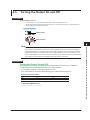
General Handling Precautions
Do Not Place Objects on Top of the Instrument
Never place objects such as other instruments or objects that contain water on top of the instrument.
Doing so may damage the instrument. For details on stacking the 2553A, see section 3.2.
Keep Electrically Charged Objects Away from the Instrument
Keep electrically charged objects away from the input and output terminals. They may damage the
internal circuitry.
Unplug during Extended Non-Use
Turn off the instrument and remove the power cord from the outlet.
When Carrying the Instrument
First, be sure to turn off the power switch and remove the power cord and other connected lead wires
and cables. When carrying the instrument, either hold the handle or hold the instrument with both
hands as shown in the figure below, and move it carefully.
WARNING
• When you hold or put away the handle, be careful not to get your hand caught between the
handle and the case.
• When you carry the instrument, be careful not to get your hand caught between the wall,
installation surface, or other objects and the instrument.
French
AVERTISSEMENT
• Lorsque vous attrapez ou rabattez la poignée, veillez à ne pas vous coincer la main entre
la poignée et l’instrument.
• Lorsque vous déplacez l’instrument, veillez à ne pas vous coincer la main entre l’instrument
et le mur, la surface d’installation ou tout autre objet.
When Cleaning the Instrument
When cleaning the case or the operation panel, turn the instrument and remove the instrument’s power
cord from the outlet. Then, wipe the instrument lightly with a clean dry cloth. Do not use chemicals
such as benzene or thinner. Doing so may cause discoloring and deformation.
3-2
IM 2553A-01EN
3.2
Installing the 2553A
1
2
WARNING
3
Preparation
• Do not install the instrument outdoors or in locations subject to rain or water.
• Install the instrument so that you can immediately remove the power cord if an abnormal or
dangerous condition occurs.
4
CAUTION
If you block the vent holes on the top and bottom of the instrument, the instrument will become
hot and may break down.
French
5
6
AVERTISSEMENT
• Ne pas installer l’instrument à l’extérieur ou dans des lieux exposés à la pluie ou à l’eau.
• Installer l’instrument de manière à pourvoir immédiatement le débrancher du secteur en
cas de fonctionnement anormal ou dangereux.
7
8
ATTENTION
Ne pas bloquer les orifices d’aération en haut et en bas de l’instrument pour éviter la
surchauffe et la panne.
9
Installation Conditions
10
Install the instrument in a place that meets the following conditions.
Vent holes are located on the top and bottom of the instrument. To prevent internal overheating, allow
for enough space around the instrument (see the figure below), and do not block the vent holes.
Do not install the instrument in a location where the air from an air conditioning system blows directly
on the output terminals or where the instrument will be affected by heat sources. Such environment
can cause errors.
11
12
5 cm or more
13
When connecting lead wires or cables, allow for enough space, above and beyond the space shown in
the figure above, to carry out the procedure.
App
Ambient temperature and humidity
Ambient temperature
Ambient humidity
IM 2553A-01EN
14
5°C to 40°C
20% RH to 80% RH (no condensation)
20% RH to 70% RH for ambient temperatures above 30°C
3-3
Index
3.2 Installing the 2553A
Note
• Condensation may form when the instrument is moved from a low temperature or humidity environment
to a high temperature or humidity environment, or when there is a sudden change in temperature. In such
cases, before you use the instrument, allow it to adjust to the surrounding temperature for at least an
hour. If you transport the instrument in its packing box, to prevent condensation, allow it to adjust to the
new ambient temperature for at least an hour before taking it out of the box.
• If the instrument has been stored in a hot-temperature, high-humidity environment, warm up the
instrument for at least a day before starting use.
Installation Orientation
Desktop
Install the instrument on a stable surface that is level in all directions and that is not slippery.
The supplied rubber stoppers can be attached to the feet at the rear of the instrument to prevent the
instrument from sliding. You can install the instrument in a tilted position using the movable legs.
Movable legs
WARNING
•
•
•
•
Do not adjust the movable legs in an unstable condition.
Do not place the instrument in any position other than those shown in the above figures.
Do not stack the instruments with the movable legs pulled out.
Only one instrument can be stacked on top of another. Do not stack multiple instruments
on top of one instrument.
French
AVERTISSEMENT
•
•
•
•
Ne pas manipuler les pieds escamotables lorsque l’instrument est instable.
Ne pas placer l’instrument dans des positions autres celles indiquées ci-dessus.
Ne pas empiler des instruments lorsque les pieds escamotables sont sortis.
Seul un instrument peut être empilé sur un autre instrument. Ne pas empiler plusieurs
instruments les uns sur les autres.
Rubber leg cap
A9088ZM
Rear bottom leg
Note
If you attach the front rubber leg cap, you will not be able to stack the 2553A.
3-4
IM 2553A-01EN
3.2 Installing the 2553A
1
Rack Mounting
To mount the instrument on a rack, use a rack mount kit (sold separately).
Item
Model 751533-E3
Model 751533-J3
Model 751534-E3
Model 751534-J3
Rack mount kit (for mounting one 2553A on an EIA standard rack)
Rack mount kit (for mounting one 2553A on a JIS standard rack)
Rack mount kit (for mounting one 2553A on an EIA dual mount rack)
Rack mount kit (for mounting one 2553A on an JIS dual mount rack)
Model
751533-E3
751533-J3
751534-E3
751534-J3
2
An outline of the mounting procedure is given below. For detailed instructions, see the manual that is
included with the rack mount kit.
3. Remove the four seals covering the rack mount attachment holes. The holes are on the sides
Preparation
4. Place seals over the feet and handle attachment holes.
5
1. Remove the handles from the sides of the instrument.
4
2. Remove the four feet from the bottom of the instrument.
of the instrument near the front.
5. Attach the rack mount kit to the instrument.
6. Mount the instrument on a rack.
6
How to remove the handle
7
Cover
Cover
Handle
8
Note
• When rack-mounting the instrument, allow at least 5 cm of space between the top panel and the rack to
prevent internal heating.
• Make sure to provide adequate support from the bottom of the instrument. Do not block the vent holes in
the process.
• Store the removed parts in a safe place.
• When rack-mounting the instrument, remove the feet from the rear of the instrument if they are coming
into contact with the rack and are thus preventing you from rack-mounting the instrument. After you have
rack-mounted the instrument, re-attach the feet to the rear of the instrument.
• Dials and output terminals protrude further out than the front panel position. Make sure you do not hit
them against the rack when mounting the instrument.
Do Not Install the Instrument in the Following Kinds of Places
•
•
•
•
•
•
•
•
3
9
10
11
12
In direct sunlight or near heat sources
In an environment with excessive amounts of soot, steam, dust, or corrosive gas
Near strong magnetic field sources
Near high-voltage equipment or power lines
In an environment subject to large levels of mechanical vibration
On an unstable surface
Outdoors or in locations subject to rain or water
Where the air from an air conditioning system blows directly on the instrument or where the
instrument will be affected by heat sources
13
14
App
IM 2553A-01EN
3-5
Index
3.3
Connecting to the Power Supply
Before Connecting the Power Supply
Make sure to follow the warnings below when connecting the power supply. Failure to do so may
cause electric shock or damage to the instrument.
WARNING
• Make sure that the power supply voltage matches the instrument’s rated supply voltage
and that it does not exceed the maximum voltage range specified for the power cord.
• Connect the power cord after checking that the power switch of the instrument is turned off.
• To prevent electric shock and fire, use a power cord for this instrument provided by
YOKOGAWA.
• Make sure to connect protective earth grounding to prevent electric shock. Connect the
power cord to a three-prong power outlet with a protective earth terminal.
• Do not use an ungrounded extension cord. If you do, the instrument will not be grounded.
• If an AC outlet that conforms to the supplied power cord is unavailable and you cannot
ground the instrument, do not use the instrument.
French
AVERTISSEMENT
• Vérifier que la tension d’alimentation correspond à la tension d’alimentation nominale
de l’instrument et qu’elle ne dépasse pas la plage de tension maximale spécifiée pour le
cordon d’alimentation.
• Brancher le cordon d’alimentation après avoir vérifié que l’interrupteur de l’instrument est
sur OFF.
• Pour éviter tout risque de choc électrique, utiliser exclusivement le cordon d’alimentation
fourni par YOKOGAWA et prévu pour l’instrument.
• Relier l’instrument à la terre pour éviter tout risque de choc électrique. Brancher le cordon
d’alimentation sur une prise de courant à trois plots reliée à la terre.
• Toujours utiliser une rallonge avec broche de mise à la terre, à défaut de quoi l’instrument
ne serait pas relié à la terre.
• En l’absence de prise secteur conforme au cordon d’alimentation et dans l’impossibilité de
mettre l’instrument à la terre, ne pas utiliser l’instrument.
3-6
IM 2553A-01EN
3.3 Connecting to the Power Supply
1
Connecting the Power Cord
1. Check that the power switch (POWER) on the front panel of the instrument is turned off.
2. Connect the power cord plug to the power inlet on the rear panel.
2
3. Connect the other end of the cord to an outlet that meets the following conditions. Use a
grounded three-prong outlet.
Specifications
100 VAC to 120 VAC, 200 VAC to 240 VAC
90 VAC to 132 VAC, 180 VAC to 264 VAC
50Hz/60Hz
48 Hz to 63 Hz
Approx. 30 VA
3
*This instrument can use a 100 V or a 200 V power supply. The maximum rated voltage
differs according to the type of power cord. Check that the voltage supplied to the
instrument is less than or equal to the maximum rated voltage of the power cord provided
with the instrument before using it (see page ii for the maximum rated voltage).
2553A
Preparation
Item
Rated supply voltage*
Permitted supply voltage range
Rated supply frequency
Permitted supply frequency range
Maximum power consumption
4
5
Three-prong outlet
6
7
8
9
10
11
12
13
14
App
IM 2553A-01EN
3-7
Index
3.4
Turning On and Off the Power Switch
Before Turning On the Power, Check That:
• The instrument is installed properly. → section 3.2, “Installing the 2553A”
• The power cord is connected properly → section 3.3, “Connecting the Power Supply”
Power Switch Location
The power switch is located in the lower left of the front panel.
Turning On and Off the Power Switch
The power switch is a push button. Press the button once to turn the instrument on and press it again
to turn the instrument off.
2553A
Off
On
Operations Performed When the Power Is Turned On
When the power switch is turned on, a self-test starts automatically. When the self-test completes
successfully, the instrument will be configured with the settings that were in use immediately before
the power was turned off. For the settings that are retained even when the power is turned off, see
appendix 5.
Check that the instrument has started normally before you use it.
If the 2553A Does Not Start Normally When the Power Is Turned On
Turn off the power switch, and check the following items.
• The power cord is securely connected.
• The correct voltage is coming to the power outlet. → section 3.3, “Connecting to the Power
Supply”
• Initialize the 2553A settings → section 13.8, “Initializing the Settings.”
If the 2553A still does not work properly after checking these items, contact your nearest
YOKOGAWA dealer for repairs. If an error code is displayed, check the information in section 13.3,
and take the appropriate actions.
Note
After turning the power switch off, wait at least 10 seconds before you turn it on again.
To Generate Accurate Output
• Allow the instrument to warm up for at least 30 minutes after turning on the power switch. If
the instrument has been stored in a hot-temperature, high-humidity environment, warm up the
instrument for at least a day before starting use.
• We recommend that the power be left on at all times.
3-8
IM 2553A-01EN
3.4 Turning On and Off the Power Switch
1
Operations Performed When the Power Is Turned Off
After the power is turned off, the instrument stores the setup parameters in its memory before shutting
down. The same is true when the power cord is disconnected from the outlet. The next time the power
is turned on, the instrument powers up using the stored settings (for the settings that are stored, see
appendix 5).
2
3
Preparation
4
5
6
7
8
9
10
11
12
13
14
App
IM 2553A-01EN
3-9
Index
3.5
Wiring Precautions
WARNING
• Ground the instrument before connecting the instrument to the target device. The power
cord that comes with the instrument is a three-prong type power cord. Insert the power cord
into a grounded three-prong outlet.
• Be sure to turn off the output before connecting or disconnecting the target device.
• To prevent damage that would occur if the OUTPUT switch is flipped inadvertently during
wiring, check that the output setting dials are all set to 0 (zero).
• Make sure to fasten the output terminal screws securely so that lead wires do not come
loose.
• Do not use lead wires whose conductive parts are exposed due to tears in the insulation or
broken cables as they may lead to a short circuit or electric shock.
• If a large inductive or capacitive load or oscillating circuit is connected to the output
terminals, the output may oscillate and cause high voltage to be applied to the output
terminals. If the output oscillates, turn off the OUTPUT switch immediately.
CAUTION
• Use lead wires that have adequate margins of withstand voltage and current capacity with
respect to the voltage or current to be sourced.
• Use twisted-pair lead wires to prevent oscillation.
• When using the 10 mV range or any of the thermocouple ranges, do not apply external
voltage or current. Doing so may damage the voltage divider inside the 2553A.
3-10
IM 2553A-01EN
3.5 Wiring Precautions
1
French
AVERTISSEMENT
2
3
Preparation
• Relier l’instrument à la terre avant de le brancher sur l’appareil cible. Le cordon d’alimentation
livré avec l’instrument est doté de trois broches. Brancher le cordon d’alimentation sur une
prise de courant à trois plots mise à la terre.
• Toujours mettre hors tension avant de brancher ou de débrancher l’appareil cible.
• Pour éviter tout endommagement si le commutateur de SORTIE (OUTPUT) était
accidentellement actionné une fois le branchement effectué, vérifier que les paramètres de
réglage de la sortie sont tous sur 0 (zéro).
• Serrer suffisamment les vis des bornes de sortie pour éviter que les câbles ne se
détachent.
• Pour éviter tout risque de court-circuit ou de choc électrique, ne pas utiliser des câbles
endommagés ou dont les fils intérieurs sont visibles.
• En cas de branchement d’une importante charge inductive ou capacitive, ou de circuit
oscillant sur les bornes de sortie, la sortie peut osciller et entraîner l’alimentation d’une
tension élevée sur les bornes de sortie. En cas d’oscillation de la sortie, mettre le
commutateur de SORTIE (OUTPUT) immédiatement hors tension.
4
5
6
7
ATTENTION
• Utiliser des câbles qui ont suffisamment de marge de tension de maintien ou de capacité
de courant par rapport à la tension ou au courant à émettre.
• Utiliser une paire torsadée de câbles pour éviter l’oscillation.
• Avec une gamme de mesure de 10 mV ou toute autre valeur de gammes de
thermocouples, ne pas alimenter en tension externe, ni courant. Cela pourrait endommager
le diviseur de tension à l’intérieur du 2553A.
8
9
10
11
12
13
14
App
IM 2553A-01EN
3-11
Index
3.6
Connecting Wires
CAUTION
• Confirm that no foreign materials are caught in the contact area between the output
terminals and the lead wires.
• Periodically confirm that the output terminals are not loose and that there are no foreign
materials caught in the contact area between the current terminals and the lead wires.
• Attaching the terminal plug upside down to the external RJ sensor input terminal of the
2553A may damage the terminal plug or the external RJ sensor input terminal. Check the
orientation before attaching the plug.
French
ATTENTION
• Vérifier l’absence de corps étrangers dans la zone de contact entre les bornes de sortie et
les câbles.
• Vérifier régulièrement que les bornes de sortie sont bien serrées et qu’il n’y a aucun corps
étrangers dans la zone de contact entre les bornes de courant et les câbles.
• Le branchement à l’envers de la fiche de raccordement sur la borne d’entrée du capteur
RJ externe du 2553A peut endommager la fiche de raccordement ou la borne d’entrée du
capteur RJ externe. Vérifier l’orientation de la fiche avant de la brancher.
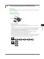
Wire the lead wires from the target device to the output terminals of the 2553A. The output terminals
are binding posts with 4 mm banana jacks (female). Wire them in the following manner.
To prevent electric shock and damage to the instrument, follow the warnings given in section 3.5, “Wiring
Precautions.”
Wiring a Voltmeter or Ammeter to the Output Terminals
Wire a voltmeter or ammeter to the output terminals using method a or b explained below.
a. The fastening screws are M6. Either wind the conductive part of the lead wire around the output
terminal screw or pinch the screw section with the crimping terminal, and then tighten the terminal
knob firmly with your hand. The terminal or knob may break if you apply excessive torque.
b. Insert the measurement leads with banana plugs into the output terminals.
Wiring Example
HI
LO(±)
2553A output
terminals
Voltmeter or ammeter
3-12
IM 2553A-01EN
3.6 Connecting Wires
Note
• Current sinking (absorption) is possible in any of the voltage or current ranges. For example, by absorbing
the current from a voltage source such as a distributor, the 2553A can simulate a load, like a two-wire
transmitter. For the maximum sink current, see “DC Voltage Sourcing” or “DC Current Sourcing” in section
2.1. Immediately after sinking current that exceeds 30 mA, errors exceeding the accuracy specifications
may occur due to the increased temperature inside the 2553A.
1
2
In the following example, the value is set to 20 mA and the polarity to negative.
+
LO
HI
4-20 mA
Preparation
3
Voltage source
(e.g., distributor)
4
−
• When using a small output range, such as 10 mV or 100 mV, wind the copper wires directly to the output
terminals. If the output terminal temperature changes as a result of making contact with the lead wires,
crimping terminals, banana plugs, or other conductors during wiring or due to ambient air movement,
errors exceeding the accuracy specifications may occur when a small output range is used. In such
situations, wait until the output stabilizes.
Wiring a Thermograph to the Output Terminals
The fastening screws are M6. Wind the thermocouple wire or the RTD lead wire around the output
terminal screw, and then tighten the terminal knob firmly with your hand. The terminal or knob may
break if you apply excessive torque. For wiring examples, see also appendixes 2 and 3.
Wiring Example
5
6
7
8
+(A)
−(B)
9
2553A output
terminals
10
Thermograph
Note
If the output terminal temperature changes as a result of making contact when wiring thermocouples,
compensating lead wires, and the like; making contact when connecting external RJ sensors; and due to
ambient air movement, errors exceeding the accuracy specifications may occur. In such situations, wait until
the output stabilizes.
11
12
13
14
App
IM 2553A-01EN
3-13
Index
3.6 Connecting Wires
Wiring to the External RJ Sensor Input Terminal
To wire an external reference junction (RJ) sensor to the external RJ sensor input terminal on the rear
panel of the 2553A, follow the procedure below.
Wiring an RJ Sensor to the Terminal Plug
1. Loosen the screws on the top of the terminal plug (these screws are used to fix lead wires in
place), and insert stripped lead wires into the lead wire connection terminals.
Insert white lead wires into the white positions of the terminal plug and red lead wires into the red positions.
• Length of stripped wire:
• Conductive cross-sectional area
7 mm
Single wire:
Twisted wire:
AWG:
0.14 mm2 to 1.5 mm2
0.14 mm2 to 1.5 mm2
28 to 16
2. Tighten the screws to fix the lead wires in place.
Screw tightening torque: 0.22 N•m to 0.25 N•m
Terminal plug
Lead wire screw Top
Terminal plug screw
Connect the lead wires to the appropriate terminals according
to the three-wire system or four-wire system of the RJ sensor.
3-wire
4-wire
Lead wire
Lead wire
connection
terminal
Bottom
No connection
Ground (GND)
(NC)
White
Red
White Red
Terminal plug pinout
Attaching the Terminal Plug to the External RJ Sensor Input
Terminal
3. Attach the terminal plug with the RJ sensor to the external RJ sensor input terminal of the
2553A.
The terminal plug cannot be attached upside down. Attach the terminal plug in the proper orientation.
4. Tighten the screws on the left and right of the terminal plug to secure the terminal plug to the
2553A.
Screw tightening torque: 0.2 N•m to 0.3 N•m
3-14
IM 2553A-01EN
Chapter 4
4.1
SETUP Menu
SETUP Menu Tree Structure
1
The SETUP menu appears when you turn the RANGE dial and select SETUP.
The available menu items are illustrated in the following tree diagram.
An overview of how to use the SETUP menu is provided in section 4.2. For details of how to operate
each menu, see the referenced section in the tree diagram.
2
3
RANGE dial
4
SETUP Menu
5
SETUP indicator on
GPIB
Set the GP-IB conditions. See section 7.3.
ADRS
6
Address
Value: 0 to 30
TYPE
7
Command type
Options: NORM (IEEE488.2)
8
COMP (2553 compatible)
LAN
Configure the network environment. See section 8.3.
9
DHCP
Use or not use DHCP.
Options: on (use)/oFF (not use)
IP
10
IP address
Value: 0.0.0.0 to 255.255.255.255 Example: 192(1).168(2).0(3).1(4)
11
MASK
Subnet mask
Value: 0.0.0.0 to 255.255.255.255 Example: 255.(1) 255.(2) 255.(3) 255(4)
GATE
12
Default gateway
13
Value: 0.0.0.0 to 255.255.255.255 Example: 255.(1) 255.(2) 255.(3) 0(4)
MAC
14
Displays the MAC address
Displayed characters: 12 characters, each character ranging from a to f and 0 to 9
Example: 00.00.(1) 12.34.(2) 56.78(3)
App
To USB on the next page
IM 2553A-01EN
4-1
Index
4.1 SETUP Menu Tree Structure
To LAN on the previous page
USB
Selects the USB communication feature
TMC
Remote control. See section 9.3.
STOR
UNIT
Mass storage. See section 6.4.
Select the unit. See section 6.6.
CEL
Celsius (°C)
FAR
Fahrenheit (°F)
RJC
Set the reference junction compensation. See section 6.5.
MODE
Select the reference junction compensation mode.
Options: AUTO, INT, MAN
VAL
Value:
Set the reference junction temperature when the RJC mode
is MAN.
–20.00°C to +60.00°C
–4.00°F to +140.00°F
R0
Value:
99.00 Ω to 101.00 Ω
ERROR
LOG
CLEAR
INIT
Set resistance R0 for when the external RJ sensor (Pt100)
is at 0°C.
Displays or clears the error log. See section 13.5.
Displays the error log
Clears the error log
Initializes the 2553A to its factory default settings. See section 13.8.
INFO
FIRM
Displays the product information. See section 13.9.
Displays the firmware version
LOGIC
BOOT
Displays the boot program version
SER.NO
Displays the device serial number
TEST
CAL
Displays the logic program version
Executes a self-test. See section 13.7.
Performs simple adjustment
For the simple adjustment procedure, see the following webpage.
http://tmi.yokogawa.com/products/generators-sources/standard/precision-dc-calibrator-2553a/
4-2
IM 2553A-01EN
4.2
Using the SETUP Menu
1
This section provides an overview of how to use the SETUP menu. For detailed explanations of how to
configure individual functions with the SETUP menu, see the relevant sections.
When the SETUP menu is displayed, only the dials and switches for setting and displaying the menu
items can be used. (Other dials and switches are disabled.) Also, displays that are not used in the
SETUP menu do not turn on.
Displays polarity or the most significant digit
At levels where a value is set or displayed, this displays +, –, or 1 when the polarity or the
most significant digit needs to be displayed.
3
4
SETUP Menu
Displays the SETUP menu
Displays the menu specified by turning the output setting dials.
At levels where a value is set or displayed, these display the value.
5
Displays auxiliary information
Displays the auxiliary information on the SETUP menu.
(auxiliary numbers in IP-address-related and LOGIC menus,
unit for settings that require it, etc.)
The display blinks if the setting has not
being confirmed. To confirm, flip the
POLARITY switch down.
2
6
7
Output setting dials
8
9
POLARITY switch
RANGE dial
10
RANGE Dial
First, to enter the SETUP menu, use this dial to select SETUP.
11
Output Setting Dials
You can use any of the output setting dials to set the menu items. However, these dials operate
separately in the following situations.
• When a value is being set, each dial sets the value of the digit immediately above it. Carrying over
and borrowing occur automatically within the selectable range.
• At the menu level for switching the auxiliary information display, the right-most output setting dial is
used to switch the display.
12
13
14
App
IM 2553A-01EN
4-3
Index
4.2 Using the SETUP Menu
POLARITY Switch
Use this switch to confirm the setting that you have changed or cancel the change and return to the
previous menu level.
• Flipping the OUTPUT switch down confirms the displayed setting.
• If there is a next menu level, the menu proceeds to that level.
• If there are values or information to be displayed, those are displayed.
• If you perform this operation on an execution menu, you cannot undo it.
• Flipping the OUTPUT switch up returns the menu to the previous level. If you perform this operation
when the display is blinking, the displayed setting will not be confirmed. The setting returns to the
original value.
Note
If you clear the error log, initialize the settings, and so forth, you cannot undo it. Confirm that it is okay to
perform such operation before execution.
4-4
IM 2553A-01EN
Chapter 5
5.1
Voltage, Current, and Resistance Sourcing
Selecting the Voltage, Current, or Resistance
Range
1
2
CAUTION
When using the 10 mV range, do not apply external voltage or current. Doing so may damage
the voltage divider inside the 2553A.
French
3
4
ATTENTION
Avec une gamme de mesure de 10 mV, ne pas alimenter en tension externe, ni courant. Cela
pourrait endommager le diviseur de tension à l’intérieur du 2553A.
5
Voltage, Current, and Resistance Sourcing
Procedure
6
Turn the RANGE dial to set the voltage, current, or resistance range.
• The indicator for the selected range illuminates.
• The unit corresponding to the selected range appears.
7
Voltage ranges
Resistance range
Current ranges
8
Example: 10 V
The 10 V indicator turns on.
9
RANGE dial
Explanation
10
Source ranges are shown below. Set the value that you want to output (output setting) within the
selected range. For information on how to set the output setting, see section 5.2.
If you change the range when the output is on, the output turns off.
11
Voltage Ranges
Select from the following.
10 mV, 100 mV, 1 V, 10 V, 30 V
12
Current Ranges
Select from the following.
1 mA, 10 mA, 30 mA, 100 mA
13
Resistance Range
400 Ω.
14
Note
The 2553A does not have an auto range feature that automatically switches the range according to the
output setting.
App
<<Command Mnemonic>>
:SOURce:FUNCtion {VOLTage|CURRent|RESistance}
:SOURce:RANGe {<Voltage>|<Current>|<Resistance>}
IM 2553A-01EN
5-1
Index
5.2
Specifying the Output Setting and Polarity
Procedure
Specifying the Output Setting
Turn the output setting dials to set the source voltage, current, or resistance.
The display shows the specified voltage, current, or resistance.
Setting the Polarity
Flip the POLARITY switch up or down to set the polarity.
Example of setting 1.5000 V
Polarity
Unit
POLARITY switch
Use each output setting dial to set the corresponding digit value,
shown by the frames.
Carrying over and borrowing occurs automatically within the
selectable range.
Explanation
Selectable Range
The selectable range and resolution of each range are as follows. For detailed specifications, see
section 14.1.
As long as you remain in the same range, you can change the output setting and polarity even while
the output is on.
Voltage Ranges
Range
10 mV
100 mV
1 V
10 V
30 V
Source Range
± 12.0000 mV
± 120.000 mV
± 1.20000 V
± 12.0000 V
± 32.000 V
Resolution
100 nV
1 µV
10 µV
100 µV
1 mV
Source Range
±1.20000 mA
±12.0000 mA
± 32.000 mA
±120.000 mA
Resolution
10 nA
100 nA
1 µA
1 µA
Selectable Range
18.00 Ω to 400.00 Ω
Resolution
0.01 Ω
Current Ranges
Range
1 mA
10 mA
30 mA
100 mA
Resistance Ranges
Range
400 Ω
5-2
IM 2553A-01EN
5.2 Specifying the Output Setting and Polarity
1
Output Setting Display
• The output setting appears flush right at the resolution of each range.
• The ratio of the output setting to the range is passed on to the output setting even when you change
the range.
Example: If the output setting is 1.5000 V (15%) at the 10 V range and you change the voltage
range to 30 V, the output setting will be 4.500 V.
2
3
10 V Range
4
5
Voltage, Current, and Resistance Sourcing
30 V Range
6
7
• When you change the range and the specified output setting is outside the selectable range of the
new range, the output setting and polarity displays blink. If you turn any of the output setting dials
in this condition but the output setting still remains outside the selectable range of the new range,
the output setting is set to the maximum or minimum setting of the new range, and the blinking will
change to solid.
<<Command Mnemonic>>
:OUTPut:POLarity {NORMal|INVerted}
:SOURce:FUNCtion {VOLTage|CURRent|RESistance}
:SOURce:LEVel {<Voltage>|<Current|<Resistance>|MINimum|MAXimum}
:SOURce:SLEVel {<Voltage>|<Current|<Resistance>|MINimum|MAXimum}
8
9
10
11
12
13
14
App
IM 2553A-01EN
5-3
Index
5.3
Turning the Output On and Off
Procedure
Flip the OUTPUT switch up.
• The output turns on. The OFF indicator turns off, and the ON indicator turns on.
• Flipping the OUTPUT switch down while the output is on will turn off the output. The ON indicator will
turn off, and the OFF indicator will turn on.
OUTPUT switch
Output terminals
Note
• When outputting current, do not open the output terminals.
When outputting voltage, do not short the output terminals.
In either case, the overload protection function will be activated, an error code will be displayed, and the
output will be turned off. The time it takes for the error to appear depends on the range and output value.
• If the output terminal temperature changes as a result of making contact with the lead wires, crimping
terminals, banana plugs, or other conductors during wiring or due to ambient air movement, errors
exceeding the accuracy specifications may occur when a small output range is used. In such situations,
wait until the output stabilizes. Also while the 2553A is generating output, keep the output terminal
temperature from changing due to the effects air conditioning, other heat sources, and the like.
Explanation
Turning the Output On and Off
When the output is turned on, the 2553A will source the specified voltage, current, or resistance from
the output terminals.
• If you change the range setting, the output automatically turns off.
• If the output setting is outside the selectable range, the output cannot be turned on.
Indicator and Output States
Output State
ON
OFF
ON Indicator (Green)
On
Off
OFF Indicator (Red)
Off
On
<<Command Mnemonic>>
:OUTPut[:STATe] <Boolean>
5-4
IM 2553A-01EN
Chapter 6
6.1
Temperature-Sensor-Simulation Thermoelectromotive-Force and Resistance Sourcing
Selecting Thermocouples and RTDs
1
2
CAUTION
When using thermocouple ranges, do not apply external voltage or current. Doing so may
damage the voltage divider inside the 2553A.
3
French
4
ATTENTION
Avec des gammes de thermocouples, ne pas alimenter en tension externe, ni courant. Cela
pourrait endommager le diviseur de tension à l’intérieur du 2553A.
5
6
Procedure
The TEMP indicator illuminates, and the TEMPERATURE dial is enabled.
2. Turn the TEMPERATURE dial to select a thermocouple (R, S, B, J, T, E, K, N, C, A, TC USER)
or RTC (Pt100, RTD USER) type.
• The indicator for the selected type turns on.
• The displayed unit will be °C.
2. Select the thermocouple or RTD type.
The indicator for the selected type turns on.
Temperature-Sensor-Simulation Thermoelectromotive-Force and Resistance Sourcing
1. Turn the RANGE dial to select TEMP.
7
8
1. Select TEMP.
The TEMP indicator turns on.
9
10
Example: B
The B indicator
turns on.
TEMPERATURE dial
11
RANGE dial
12
13
14
App
IM 2553A-01EN
6-1
Index
6.1 Selecting Thermocouples and RTDs
Explanation
The available thermocouple and RTD types are shown below. If you change the type when the output
is on, the output turns off.
Thermocouple
Select from the following.
R, S, B, J, T, E, K, N, C, A, TC USER*
* If you select TC USER, the thermoelectromotive force of a user-defined thermocouple can be
sourced. For details how to write user-defined data to the 2553A, see section 6.4. For the data
definition specifications, see appendix 4.
RTD
Select from the following.
Pt100, RTD USER*
* If you select RTD USER, the resistance of a user-defined RTD can be sourced. For details how to
write user-defined data to the 2553A, see section 6.4. For the data definition specifications, see
appendix 4.
<<Command Mnemonic>>
:SOURce:FUNCtion {TCouple|RTD}
:SOURce:TYPE {R|S|B|J|T|E|K|N|C|A|PT100|USER}
6-2
IM 2553A-01EN
6.2
Setting the Temperature
1
2
Procedure
Setting the Temperature
Turn the output setting dial to set the temperature.
3
The display shows the specified temperature.
Setting the Polarity
Flip the POLARITY switch up or down to set the polarity.
4
Example of setting 100°C
Polarity
Unit
6
Use each output setting dial to set the corresponding digit value,
shown by the frames.
Carrying over and borrowing occurs automatically within the
selectable range.
7
Explanation
8
Selectable Range
The selectable range and resolution of each thermocouple and RTD are as shown below. For detailed
specifications, see section 14.1.
You can change the output setting and polarity even while the output is on. However, if the output
setting goes outside the selectable range when you change the polarity, the output turns off, and the
output setting and polarity displays blink.
Thermocouple
Source Range
-50°C to +1768°C
-50°C to +1768°C
0°C to +1820°C
-210°C to +1200°C
-270°C to +400°C
-270°C to +1000°C
-270°C to +1300°C
-270°C to +1300°C
0°C to +2315°C
0°C to +2500°C
-9999.9°C to +9999.9°C
11
12
RTD
Source Range
-200.0°C to +850.0°C
-9999.9°C to +9999.9°C
Resolution
0.1°C
0.1°C
* If you select RTD USER, the resistance corresponding to the user-defined temperature can be
sourced. For a detailed procedure, see section 6.4. For details on definition expressions, see
appendix 4.
IM 2553A-01EN
9
10
Resolution
0.1°C
0.1°C
0.1°C
0.1°C
0.1°C
0.1°C
0.1°C
0.1°C
0.1°C
0.1°C
0.1°C
* If you select TC USER, the thermoelectromotive force corresponding to the user-defined
temperature can be sourced. For a detailed procedure, see section 6.4. For details on definition
expressions, see appendix 4.
Type
Pt100
RTD USER
Temperature-Sensor-Simulation Thermoelectromotive-Force and Resistance Sourcing
POLARITY switch
Type
R
S
B
J
T
E
K
N
C
A
TC USER
5
6-3
13
14
App
Index
6.2 Setting the Temperature
Output Setting Display
• The output setting appears flush right at the resolution of each thermocouple or RTD.
• When you change the type or polarity and the specified output setting is outside the selectable
range of the new type, the output setting and polarity displays blink. If you turn any of the output
setting dials in this condition but the output setting still remains outside the selectable range of the
new type, the output setting is set to the maximum or minimum setting of the new type, and the
blinking will change to solid.
<<Command Mnemonic>>
6-4
:OUTPut:POLarity {NORMal|INVerted}
:SOURce:FUNCtion {TCouple|RTD}
:SOURce:LEVel {<Temperature>|MINimum|MAXimum}
:SOURce:SLEVel {<Temperature>|MINimum|MAXimum}
IM 2553A-01EN
6.3
Turning the Output On and Off
1
2
Procedure
Flip the OUTPUT switch up.
• The output turns on. The OFF indicator turns off, and the ON indicator turns on.
• Flipping the OUTPUT switch down while the output is on will turn off the output. The ON indicator will
turn off, and the OFF indicator will turn on.
4
OUTPUT switch
5
Output terminals
6
• When outputting temperature, do not short the output terminals.
• If the output terminal temperature changes as a result of making contact when wiring thermocouples,
compensating lead wires, and the like; making contact when connecting external RJ sensors; and due to
ambient air movement, errors exceeding the accuracy specifications may occur. In such situations, wait
until the output stabilizes. Also while the 2553A is generating output, keep the output terminal temperature
from changing due to the effects air conditioning, other heat sources, and the like.
Explanation
7
8
9
Turning the Output On and Off
When the output is turned on, the 2553A will source the thermoelectromotive force or resistance
corresponding to the specified temperature from the output terminals.
• If you change the type, the output automatically turns off.
• If the output setting is outside the selectable range, the output cannot be turned on.
10
Indicator and Output States
ON Indicator (Green)
On
Off
Temperature-Sensor-Simulation Thermoelectromotive-Force and Resistance Sourcing
Note
Output State
ON
OFF
3
11
OFF Indicator (Red)
Off
On
12
<<Command Mnemonic>>
:OUTPut[:STATe] <Boolean>
13
14
App
IM 2553A-01EN
6-5
Index
6.4
Writing User-Defined Data
CAUTION
The USB mass storage feature is used to write user-defined data to the 2553A. To prevent
the 2553A from a computer virus infection, before connecting a PC to the 2553A, check that
the PC is not infected by a computer virus. Connecting a 2553A that has been infected with a
computer virus may infect other devices when they are connected to the 2553A.
If you find out that the PC connected to the 2553A is infected with a computer virus, turn off
the 2553A. Computer viruses in the 2553A will be erased.
French
ATTENTION
Le dispositif de mémoire de masse USB permet l’écriture dans 2553A de données définies
par l’utilisateur. Pour protéger le 2553A contre les virus informatiques, avant de brancher un
PC sur le 2553A, vérifier que le PC est exempt de virus. Le branchement du 2553A infecté
par un virus informatique aura pour effet d’infecter les autres appareils branchés sur le 2553A.
S’il apparaît que le PC branché sur le 2553A est infecté par un virus informatique, mettre le
2553A hors tension. Les virus informatiques contenus dans le 2553A seront supprimés.
Procedure
Start the 2553A and the PC. Check that they have started normally.
For details on how to turn the 2553A power switch on and the operations performed when the power is
turned on, see section 3.4.
Setting the 2553A’s USB Communication Feature to Mass
Storage
1. Turn the RANGE dial to select SETUP.
The SETUP menu appears.
1. Select SETUP.
The SETUP indicator turns on.
RANGE dial
Selecting the USB Interface
2. Turn an output setting dial to select USB.
3. Flip the POLARITY switch down.
The USB menu appears.
6-6
IM 2553A-01EN
6.4 Writing User-Defined Data
1
Selecting the Mass Storage Feature
4. Turn an output setting dial to select STOR.
5. Flip the POLARITY switch down.
2
The USB feature is confirmed.
3
POLARITY switch
3. Display the USB menu.
5. Confirm the USB feature.
4
Output setting dials (use any)
2. Select USB.
4. Select STOR.
5
Connecting the 2553A to the PC through USB
6. Using a USB cable, connect the USB port (type B) on the rear panel of the 2553A to the PC.
6
See the USB interface specifications in section 9.1 and the connection diagram in section 9.2.
Temperature-Sensor-Simulation Thermoelectromotive-Force and Resistance Sourcing
Operations on the PC
7
Opening the Computer Folder
7. Open the Computer folder from the Windows Start menu.
8
9
10
11
12
13
14
App
IM 2553A-01EN
6-7
Index
6.4 Writing User-Defined Data
Writing User-Defined Data
8. Double-click the 2553A IN drive in the computer folder.
The 2553A IN folder opens.
9. Place the user-defined data file (TCUSER.TXT or RTDUSER.TXT) that you created in the
2553A IN folder.
• For the user-defined data definition specifications, see appendix 4.
• The user-defined data file name is fixed. When placing the file in the 2553A IN folder, an error will not
occur even if a different file name is used. However, make sure to rename the file to TCUSER.TXT or
RTDUSER.TXT before performing step 10 on the next page.
Example in Which a Thermocouple User-Defined Data File (TCUSER) Is Placed in the
2553A IN Folder
10.Right-click 2553A IN in the navigation window. On the shortcut menu, click Eject.
• The 2553A IN and 2553A OUT drives are ejected from the computer folder. The user-defined data in the
file in the 2553A IN folder is written to the 2553A’s internal memory, and then the 2553A IN and 2553A
OUT drives appear again in the computer folder.
• The file in the 2553A IN folder will be deleted.
• The contents written in the 2553A’s internal memory are saved to TCUSER.TXT or RTDUSER.TXT in
the 2553A OUT folder.
Shortcut menu
Navigation
window
Click Eject.
6-8
IM 2553A-01EN
6.4 Writing User-Defined Data
1
If User-Defined Data Contains Errors
In step 10, the 2553A checks for errors in the data. If an error is found, the 7-segment LED will display
an error code, and the contents in the internal memory of the 2553A will not updated.
2
Explanation
This section explains how to write user-defined data. After writing user-defined data to the 2553A, you
can use the TEMPERATURE dial to set the source type to TC USER or RTD USER and source the
user-defined thermocouple thermoelectromotive force or RTD resistance. For the procedure to select
the source type, see section 6.1. For the data definition specifications, see appendix 4.
4
Mass Storage Feature
To exchange user-defined data files between the 2553A and PC, the 2553A’s USB communication
feature must be set to mass storage.
To remotely control the 2553A with communication commands, the USB communication feature must
be set to remote control protocol (TMC). For the procedure, see section 9.3.
Connecting the 2553A to the PC through USB
Note
• You can connect the USB cable before or after the 2553A and PC have started. Do not connect the cable
while they are in the middle of the startup procedure.
• Do not connect or remove the USB cable while user-defined data is being written. Doing so may prevent
the data from being written correctly. It may also cause the 2553A or PC to run abnormally.
5
6
Temperature-Sensor-Simulation Thermoelectromotive-Force and Resistance Sourcing
The USB port on the rear panel of the 2553A is type B. The USB port on the PC is type A. Connect the
2553A to the PC using a USB cable with a type B connector on one end and type A connector on the
other.
7
8
9
2553A IN and 2553A OUT Folders
If the 2553A and PC are running normally and the 2553A’s USB communication feature is set to mass
storage, when you connect them with a USB cable, 2553A IN and 2553A OUT drives appear in the
computer folder of the PC.
• When the USB cable is connected, the PC’s autoplay feature may be activated for the 2553A IN
and 2553A OUT drives. If this happens, you can also open the folders by clicking Open folder to
view files in the autoplay window.
• The 2553A IN folder is a read/write folder. This is where you place user-defined data files to be
written to the 2553A.
• The 2553A OUT folder is a read-only folder. This is where the contents of the user-defined data
written in the 2553A’s internal memory are saved in a file.
Writing User-Defined Data
The ejection of the 2553A IN drive causes the user-defined data to be written to the 2553A’s internal
memory. If written data already exists, it will be updated.
• When the data is written, the file in the 2553A IN folder is deleted.
• When the data is written, the data written in the 2553A’s internal memory is saved as a file in the
2553A OUT folder. The file data is updated.
• Since the 2553A OUT folder is read-only, you can use a text editor to view the file in the folder, but
you cannot save or delete the file.
• You can delete the data written in the 2553A’s internal memory by using a communication
command. For details on user-definition commands, see “SOURce Group” in chapter 11.
IM 2553A-01EN
3
6-9
10
11
12
13
14
App
Index
6.4 Writing User-Defined Data
Definition file
The names of the user-defined data files saved in the 2553A IN and 2553A OUT folders are fixed.
The name is not case sensitive.
• Thermocouple user-defined data file name: TCUSER.TXT
• RTD user-defined data file name: RTDUSER.TXT
If User-Defined Data Contains Errors
If there is an error in the user-defined data, an error will occur. If an error occurs, the contents in the
internal memory of the 2553A will not be updated.
Error File
When an error occurs, the information is saved in a file in the 2553A OUT folder.
• TC USER error file name: ERRORTCUSER.TXT
• RTD USER error file name: ERRORRTDUSER.TXT
For details on errors, see “Definition Specifications” or “User-Definition Error Messages” in appendix 4.
If the user-defined data is correct and the contents in the internal memory of the 2553A is updated,
the error file is deleted.
When User-Defined Data Is Not Written in Internal Memory
In the factory default condition or when user-defined data is deleted with a communication
command, the 2553A will not have data written in its internal memory. If you select to source a userdefined thermoelectromotive force or resistance, the 2553A will respond in the following manner.
Output setting
Polarity
RJC indicators
Output (OUTPUT)
Output setting query using a communication command
Blinking bars (-----) will appear.
Will turn off.
Solid indicators will change to blinking.
The output cannot be turned on.
9.91E+37 will be returned.
<<Command Mnemonic>>
•Thermocouple
:SOURce:TCouple:DEFine <String>
:SOURce:TCouple:DELete
:SOURce:TCouple:SETTing?
:SOURce:TCouple:TYPE <String>
:SOURce:TCouple:WRITe
•RTD
:SOURce:RTD:DEFine <String>
:SOURce:RTD:DELete
:SOURce:RTD:SETTing?
:SOURce:RTD:TYPE <String>
:SOURce:RTD:WRITe
6-10
IM 2553A-01EN
6.5
Setting Reference Junction Compensation
1
2
Procedure
1. Turn the RANGE dial to select TEMP.
The TEMP indicator illuminates, and the TEMPERATURE dial is enabled.
3
2. Turn the TEMPERATURE dial to select R.J. TEMP.
• The R.J. TEMP indicator turns on.
• The displayed unit will be °C.
2. Select R.J. TEMP.
The R.J. TEMP indicator turns on.
4
1. Select TEMP.
The TEMP indicator turns on.
5
6
RANGE dial
7
Setting the Reference Junction Compensation Mode
3. Turn the right-most output setting dial to set the reference junction compensation (RJC) mode
to auto, internal, or manual input.
• The display shows the selected reference junction temperature.
• You can also select the reference junction compensation mode from the SETUP menu. For the SETUP
menu tree structure and operating procedure, see chapter 4.
Auto
When an external RJ
sensor is connected
Right-most output
setting dial
Internal
: On
When an external RJ sensor is not connected
After several Internal RJC is applied.
seconds
When an external RJ sensor is connected and the 2553A
has detected it
: Blinking
: Off
Manual input
When the setting is not
0.00°C
Temperature-Sensor-Simulation Thermoelectromotive-Force and Resistance Sourcing
TEMPERATURE dial
8
9
10
11
12
When the setting is
0.00°C
Setting the Reference Junction Temperature When the RJC Mode Is Manual Input
4. If you selected manual input, turn an output setting dial other than the right-most dial to set
the reference junction temperature.
13
14
App
IM 2553A-01EN
6-11
Index
6.5 Setting Reference Junction Compensation
Reference Junction Temperature Display
Setting Resistance R0 of an External RJ Sensor
You want to use the measured temperature of an external RJ sensor for the reference junction
temperature, set the resistance for when the RJ sensor is at 0°C.
1. Turn the RANGE dial to select SETUP.
The SETUP menu appears.
1. Select SETUP.
The SETUP indicator turns on.
RANGE dial
2. Turn an output setting dial to select RJC.
3. Flip the POLARITY switch down.
The RJC menu appears.
POLARITY switch
3. Displays the RJC menu
6-12
Output setting dials (use any)
2. Select RJC.
IM 2553A-01EN
6.5 Setting Reference Junction Compensation
1
4. Turn an output setting dial to select R0.
5. Flip the POLARITY switch down.
The current R0 value appears.
2
3
POLARITY switch
5. Display the R0 value.
4
Output setting dials (use any)
4. Select R0.
5
6. Turn the four output setting dials to set the R0 value.
7. Flip the POLARITY switch down.
The R0 value is confirmed.
6
Temperature-Sensor-Simulation Thermoelectromotive-Force and Resistance Sourcing
7
POLARITY switch
7. Confirm the set R0 value.
8
Output setting dials (four)
6. Set the R0 value.
Explanation
The 2553A can source thermoelectromotive force (voltage) that corresponds to specified temperatures
after performing reference junction compensation. It is also possible to source thermoelectromotive
force without reference junction compensation.
Reference Junction Compensation Mode
Select the reference junction compensation (RJC) mode from the available options below. The 2553A
corrects the sourced thermoelectromotive force (RJC) according to the selected mode.
Auto
9
10
11
12
• When an External RJ Sensor Is Detected
When the 2553A detects that an RJ sensor is connected to the external RJ sensor input terminal
on the rear panel, the 2553A sources thermoelectromotive force that is corrected using the
temperature measured by the external RJ sensor.
• When an External RJ Sensor Is Not Detected
If an RJ sensor is not connected to the 2553A or is not detected, the 2553A applies its internal
RJC.
RJ sensors 257875 are sold separately as accessories. An RTD Pt100 can also be used as an RJ
sensor.
13
14
App
Internal
The 2553A sources thermoelectromotive force that is corrected using the temperature of its output
terminals.
IM 2553A-01EN
6-13
Index
6.5 Setting Reference Junction Compensation
Manual Input
You can set the reference junction temperature with the output setting dials. The 2553A sources
thermoelectromotive force that is corrected using the specified temperature. If you do not want to
apply correction (not use the RJC function), set the temperature to 0.00°C.
Selectable range: -20.00°C to +60.00°C
Reference Junction Temperature Display
The reference junction temperature is displayed with 0.01° resolution.
• While correcting the source thermoelectromotive force with an external or internal reference junction
temperature, if the reference junction temperature goes outside the specification range, the RJC
indicator will blink.
• If you change the polarity from positive to negative in manual input mode and the setting goes
outside the manual-input selectable range, the setting and polarity displays will blink. If you turn
any of the output setting dials in this condition but the setting still remains outside the manual-input
selectable range, the setting is changed to –20.00°C, and the blinking will change to solid.
Resistance R0 of the External RJ Sensor
Set the resistance for when the RJ sensor (RTD Pt100) you want to use is at 0°C. The default value is
100.00 Ω.
Selectable range S: 99.00 Ω to 101.00 Ω
<<Command Mnemonic>>
:SOURce:RJC:MODE {AUTO|INTernal|MANual}
:SOURce:RJC:STATe?
:SOURce:RJC:TEMPerature:AUTO
:SOURce:RJC:TEMPerature:EXTernal?
:SOURce:RJC:TEMPerature:INTernal?
:SOURce:RJC:TEMPerature:MANual
:SOURce:RJC:RESister?
:SYSTem:RJC:RESister <Resistance>
6-14
IM 2553A-01EN
6.6
Selecting the Temperature Unit
1
2
Procedure
1. Turn the RANGE dial to select SETUP.
The SETUP menu appears.
3
1. Select SETUP.
The SETUP indicator turns on.
4
5
RANGE dial
6
Temperature-Sensor-Simulation Thermoelectromotive-Force and Resistance Sourcing
2. Turn an output setting dial to select UNIT.
3. Flip the POLARITY switch down.
7
The temperature unit menu appears.
4. Turn an output setting dial to select CEL or FAR.
5. Flip the POLARITY switch down.
8
The selected temperature unit is confirmed.
9
10
POLARITY switch
3. Display the temperature unit menu.
5. Confirm the selected temperature unit.
Output setting dials (use any)
2. Select UNIT.
4. Select CEL or FAR.
11
Explanation
On models with the -UF suffix code, you can select the temperature unit.
You can set the temperature using the selected unit.
CEL: °C
FAR: °F
12
13
<<Command Mnemonic>>
:SYSTem:UNIT {C|CEL|F|FAR}
14
App
IM 2553A-01EN
6-15
Index
Chapter 7
7.1
GP-IB Interface
GP-IB Interface Features and Specifications
1
2
GP-IB Interface Features
Reception Feature
• With the exception of turning the power switch on and off, you can use the reception feature to
specify the same settings that you specify by using the front panel keys.
• The 2553A can receive panel setup parameters, error codes, and other output requests from a
controller.
• The 2553A can receive status report commands.
3
4
Transmission Feature
The 2553A can transmit panel setup parameters, status byte, error codes that occur, and so on.
5
Note
Talk-only, listen-only, and controller capabilities are not available.
6
GP-IB Interface Specifications
Item
Supported devices
7
GP-IB Interface
Electrical and mechanical
Functional specifications
Protocol
Code
Mode
Address
Clear remote mode
Specifications
National Instruments Corporation
• PCI-GPIB or PCI-GPIB+
• PCIe-GPIB or PCIe-GPIB+
• PCMCIA-GPIB or PCMCIA-GPIB+
(not supported on Windows Vista or Windows 7.)
• GPIB-USB-HS
Driver NI-488.2M Version 2.8.1 and later
Conforms to IEEE St'd 488-1978
See the table below.
Complies with IEEE St’d 488.2-1992 (when using standard commands)
ISO (ASCII) codes
Addressable mode
The address can be set in the range of 0 to 30.
Clear remote mode by flipping the OUTPUT switch to the LOCAL side.
This is not possible when local lockout has been activated by the controller.
8
9
10
Functional Specifications
Function
Source handshaking
Acceptor handshaking
Talker
Subset Name
SH1
AH1
T6
Listener
L4
Service request
Remote local
Parallel polling
Device clear
Device trigger
Controller
Electric characteristics
SR1
RL1
PP0
DC1
DT1
C0
E1
Description
Full source handshaking capability
Full acceptor handshaking capability
Basic talker capability, serial polling, and untalk on MLA (My
Listen Address). No talk-only capability.
Basic listener capability and unlisten on MTA (My Talk Address).
No listen-only capability
Full service request capability
Full remote/local capability
No parallel polling capability
Full device clear capability
Device trigger capability
No controller capability
Open collector
11
12
13
14
App
IM 2553A-01EN
7-1
Index
7.1 GP-IB Interface Features and Specifications
Switching between Remote and Local Modes
When Switching from Local to Remote Mode
The 2553A switches to remote mode when it is in local mode and receives a REN (Remote Enable)
message from the PC.
• The REMOTE indicator turns on.
• All dials and switches are disabled except for the flipping of the OUTPUT switch to the LOCAL
side to change the 2553A to local mode.
• Settings entered in local mode are retained even when the 2553A switches to remote mode.
When Switching from Remote to Local Mode
When the 2553A is in remote mode and you flip the OUTPUT switch to the LOCAL side, the
2553A switches to local mode. This is not possible when local lockout (see section 11.4) has been
activated by the controller.
• The REMOTE indicator turns off.
• Dials and switches can be used.
• Settings entered in remote mode are retained even when the 2553A switches to local mode.
Note
You cannot use the GP-IB interface simultaneously with other interfaces (USB or Ethernet).
7-2
IM 2553A-01EN
7.2
Connecting through the GP-IB Interface
1
2
GP-IB Cable
The 2553A is equipped with an IEEE St’d 488-1978 24-pin GP-IB connector. Use a GP-IB cable that
conforms to this standard.
Connection Method
3
Connect the cable as shown below.
4
2553A
5
GP-IB port
6
Notes on Connection
7
GP-IB Interface
• Firmly tighten the screws on the GP-IB cable connector.
• On the PC end, use a GP-IB board (or card) made by National Instruments. For details, see
section 7.1.
• The 2553A may not operate properly if the 2553A is connected to the PC through converters (such
as a GP-IB to USB converter). For more details, contact your nearest YOKOGAWA dealer.
• Several cables can be used to connect multiple devices. However, no more than 15 devices,
including the controller, can be connected on a single bus.
• When connecting multiple devices, you must assign a unique address to each device.
• Use cables that are no longer than 2 m in length to connect devices.
• Make sure the total length of all cables does not exceed 20 m.
• When devices are communicating, have at least two-thirds of the devices on the bus turned on.
• To connect multiple devices, wire them in a daisy-chain or star configuration as shown below.
You can also mix these configurations. Loop configuration is not allowed.
8
9
10
11
12
13
14
App
IM 2553A-01EN
7-3
Index
7.2 Connecting through the GP-IB Interface
CAUTION
Be sure to turn off the PC and the 2553A before you connect or remove communication
cables. Otherwise, erroneous operation may result, or the internal circuitry may break.
French
ATTENTION
Toujours mettre le PC et le 2553A hors tension avant de brancher ou de débrancher des
câbles de communication, pour éviter tout dysfonctionnement ou panne du circuit interne.
7-4
IM 2553A-01EN
7.3
Configuring the 2553A GP-IB Settings
1
2
Procedure
1. Turn the RANGE dial to select SETUP.
The SETUP menu appears.
3
1. Select SETUP.
The SETUP indicator turns on.
4
5
RANGE dial
6
Selecting the GP-IB Interface
2. Turn an output setting dial to select GPIB.
7
3. Flip the POLARITY switch down.
GP-IB Interface
The GP-IB menu appears.
8
9
POLARITY switch
3. Display the GP-IB menu.
Output setting dials (use any)
10
2. Select GPIB.
Setting the GP-IB Address
11
4. Turn an output setting dial to select ADRS.
5. Flip the POLARITY switch down.
A GP-IB address appears.
12
13
POLARITY switch
5. Display the GP-IB address.
14
Output setting dials (use any)
4. select ADRS.
App
IM 2553A-01EN
7-5
Index
7.3 Configuring the 2553A GP-IB Settings
6. Turn the two output setting dials on the right to set the GP-IB address.
7. Flip the POLARITY switch down.
The GP-IB address is confirmed.
8. Flip the POLARITY switch up.
The menu returns to the previous level.
POLARITY switch
Output setting dials (the right two)
7. Confirm the GP-IB address settings.
6. Set the GP-IB address.
Setting the Command Type
4. Turn an output setting dial to select TYPE.
5. Flip the POLARITY switch down.
The command type menu appears.
6. Turn an output setting dial to select NORM or COMP.
7. Flip the POLARITY switch down.
The command type is confirmed.
POLARITY switch
5. Display the command type menu.
7. Confirm the command type setting.
7-6
Output setting dials (use any)
4. Select TYPE.
6. Select NORM or COMP.
IM 2553A-01EN
7.3 Configuring the 2553A GP-IB Settings
1
Explanation
To use the GP-IB interface, you must set the GP-IB address and command type.
2
GP-IB Address
Set the GP-IB address in the following range. Assign a unique address.
0 to 30
3
Command Type
The 2553A is compatible with the remote control commands of its predecessor model, the 2553. Select
the command type depending on your situation.
•NORM: Normal commands. These commands comply with IEEE488.2 (see chapter 11).
• COMP: 2553 compatible commands.
4
5
Notes on Using Existing Programs
6
7
GP-IB Interface
To use an existing 2553 program on the 2553A, note the following points.
• Insert a wait time of 1 second in operations that change the output. If you do not, the program
may not work properly.
• The 2553A stores the polarity and output setting separately for the voltage, current, and
temperature. The 2553 stores only a single set of polarity and output setting. As such, to use an
existing 2553 program, you need to change the range and then specify the polarity and output
setting for the voltage, current, and temperature so that they are congruent with the 2553A
settings.
8
For details on COMP commands, see the 2553 user’s manual.
Note
• Only use a single communication interface: USB, GP-IB, or Ethernet. If you send commands
simultaneously from more than one communication interface, the 2553A will not execute the commands
properly.
• When the controller is communicating with the 2553A or with other devices through GP-IB, do not change
the address.
• Each device that is connected in a GP-IB system has its own unique address. This address is used to
distinguish between different devices. Therefore, you must assign a unique address to the 2553A when
connecting it to a PC or other device.
• The command type setting takes effect when you turn the 2553A off and then back on. If you select
COMP, the 2553A will not accept standard commands nor communicate using the USB or LAN interface.
9
10
11
12
13
14
App
IM 2553A-01EN
7-7
Index
7.4
Responses to Interface Messages
Responses to Interface Messages
Responses to Uni-Line Messages
• IFC (Interface Clear)
Clears the talker and listener functions. Stops data transmission if it is in progress.
• REN (Remote Enable)
Switches between the remote and local modes.
IDY (Identify) is not supported.
Responses to Multi-Line Messages (Address commands)
• GTL (Go To Local)
Switches the instrument to local mode.
• SDC (Selected Device Clear)
• Clears the program message (command) being received and the output queue (see section
12.5).
•Discards *OPC and *OPC? commands that are being executed.
• Immediately aborts *WAI and COMMunicate:WAIT commands.
PPC (Parallel Poll Configure) and TCT (Take Control) are not supported.
• GET (Group Execute Trigger)
When the GP-IB command type is set to COMP (compatible commands), this command outputs
information about configuration changes and operation status.
Responses to Multi-Line Messages (Universal commands)
• LLO (Local Lockout)
Prohibits switching to local mode through the use of the OUTPUT key on the front panel.
• DCL (Device Clear)
The same operation as the SDC message.
• SPE (Serial Poll Enable)
Sets the talker function on all devices on the bus to serial polling mode. The controller will poll
each device one by one.
• SPD (Serial Poll Disable)
Clears the serial polling mode of the talker function on all devices on the bus.
PPU (Parallel Poll Unconfigure) is not supported.
What Are Interface Messages?
Interface messages are also referred to as interface commands or bus commands. They are
commands that are issued by the controller. They are classified as follows:
Uni-line Messages
A single control line is used to transmit uni-line messages. The following three types are available.
• IFC(Interface Clear)
• REN(Remote Enable)
• IDY(Identify)
7-8
IM 2553A-01EN
7.4 Responses to Interface Messages
Multi-line Messages
Eight data lines are used to transmit multi-line messages. The messages are classified as follows:
2
• Address Commands
Some address commands are valid when a device is designated as a listener, and some are
valid when it is designated as a talker. The following five commands are available.
3
Commands that are valid on an instrument that is designated as a listener
• GTL(Go To Local)
• SDC(Selected Device Clear)
• PPC(Parallel Poll Configure)
• GET(Group Execute Trigger)
4
A command that is valid on an instrument that is designated as a talker
• TCT(Take Control)
5
• Universal Commands
There are other interface messages: listener-address, talk-address, and secondary commands.
Interface messages
Universal
commands
8
10
Listener
address
7
9
Multi-line messages
Address
commands
6
GP-IB Interface
Universal commands are available to all devices regardless of their listener or talker designation.
The following five commands are available.
• LLO(Local Lockout)
• DCL(Device Clear)
• PPU(Parallel Poll Unconfigure)
• SPE(Serial Poll Enable)
• SPD(Serial Poll Disable)
Uni-line
messages
1
Talker
address
11
Secondary
command
12
The 2553A supports interface messages marked with a «.
Note
Difference between SDC and DCL
In multi-line messages, SDC messages are those that require talker or listener designation and DCL
messages are those that do not require a designation. Therefore, SDC messages are directed at a particular
instrument while DCL messages are directed at all instruments on the bus.
13
14
App
IM 2553A-01EN
7-9
Index
Chapter 8
8.1
Ethernet Interface
Ethernet Interface Features and Specifications
1
2
Ethernet Interface Features
Reception Feature
• With the exception of turning the power switch on and off, you can use the reception feature to
specify the same settings that you specify by using the front panel keys.
• The 2553A can receive panel setup parameters, error codes, and other output requests from a
controller.
• The 2553A can receive status report commands.
3
4
Transmission Feature
The 2553A can transmit panel setup parameters, status byte, error codes that occur, and so on.
5
Ethernet Interface Specifications
Item
Number of ports
Connector type
Electrical and mechanical
Simultaneous connections
Transmission system
Communication protocol
Supported services
Specifications
1
RJ-45 connector
IEEE802.3 compliant
3
ETHERNET(100BASE-TX/10BASE-T)
TCP/IP(VXI-11)
VXI-11 server, DHCP client
6
7
8
When Switching from Local to Remote Mode
The 2553A switches to remote mode when it is in local mode and receives a
:COMMunicate:REMote ON command from the PC.
Ethernet Interface
Switching between Remote and Local Modes
9
• The REMOTE indicator turns on.
• All dials and switches are disabled except for the flipping of the OUTPUT switch to the LOCAL
side to change the 2553A to local mode.
• Settings entered in local mode are retained even when the 2553A switches to remote mode.
When Switching from Remote to Local Mode
When the 2553A is in remote mode and you flip the OUTPUT switch to the LOCAL side,
the 2553A switches to local mode. However, this does not work if the 2553A has received a
:COMMunicate:LOCKout ON command from the PC. The 2553A switches to local mode when it
receives a :COMMunicate:REMote OFF command from the PC, regardless of the local lockout
state.
• The REMOTE indicator turns off.
• Dials and switches can be used.
• Settings entered in remote mode are retained even when the 2553A switches to local mode.
Note
10
11
12
13
14
You cannot use the Ethernet interface simultaneously with other interfaces (GP-IB or USB).
App
IM 2553A-01EN
8-1
Index
8.2
Connecting to the Ethernet Interface
Connection Method
Connect a UTP (Unshielded Twisted-Pair) or STP (Shielded Twisted-Pair) cable that is connected to a
hub or other network device to the Ethernet port on the 2553A rear panel.
Hub or router that supports 100BASE-TX/10BASE-T
PC
UTP or STP cable
(straight cable)
Network card
2553A
Ethernet port
RJ-45 modular jack
Notes on Connection
• To connect the 2553A to a PC through a hub or router, use straight cables. To directly connect the
2553A to a PC (one-to-one connection), use a crossover cable.
• Use a network cable that supports the data rate of your network.
8-2
IM 2553A-01EN
8.3
Configuring the 2553A Ethernet Settings
1
2
Procedure
1. Turn the RANGE dial to select SETUP.
The SETUP menu appears.
1. Select SETUP.
The SETUP indicator turns on.
3
4
5
RANGE dial
6
Selecting the Ethernet Interface
2. Turn an output setting dial to select LAN.
3. Flip the POLARITY switch down.
7
The LAN menu appears.
8
Ethernet Interface
9
POLARITY switch
3. Display the LAN menu.
Output setting dials (use any)
2. Select LAN.
10
Turning DHCP On and Off
4. Turn an output setting dial to select DHCP.
5. Flip the POLARITY switch down.
11
The DHCP menu appears.
6. Turn an output setting dial to select ON or OFF.
7. Flip the POLARITY switch down.
12
The DHCP setting is confirmed.
8. Flip the POLARITY switch up.
The menu returns to the previous level.
13
14
POLARITY switch
5. Display the DHCP menu.
7. Confirm the DHCP setting.
IM 2553A-01EN
App
Output setting dials (use any)
4. Select DHCP.
6. Select ON or OFF.
8-3
Index
8.3 Configuring the 2553A Ethernet Settings
Setting the IP Address, Subnet Mask, and Default Gateway
4. Turn an output setting dial to select IP (IP address), MASK (subnet mask), or GATE (default
gateway).
5. Flip the POLARITY switch down.
Of the four octets of the IP, MASK, or GATE, the first octet appears.
POLARITY switch
5. Display the first octet of the four
octets of the IP, MASK, or GATE.
Output setting dials (use any)
4. Select IP, MASK, or GATE.
6. Turn the right-most output setting dial to select the octet number (1 to 4) you want to set.
7. Turn the three output setting dials to set the selected octet value.
8. Repeat steps 6 and 7 to set the four octets.
9. Flip the POLARITY switch down.
The IP, MASK, or GATE setting is confirmed.
Displays the octet value of IP,
MASK, or GATE
POLARITY switch
9. Confirm the IP, MASK,
or GATE setting.
8-4
Output setting dials (three)
7. Set the value of the selected
octet.
8. Repeat steps 6 and 7.
Displays the octet number
Right-most output setting dial
6. Select the octet number you
want to set.
IM 2553A-01EN
8.3 Configuring the 2553A Ethernet Settings
1
Displaying the MAC address
4. Turn an output setting dial to select MAC.
5. Flip the POLARITY switch down.
2
Of the six octets of the MAC address, the first and second octets appear.
3
4
POLARITY switch
5. Display the first and second octets of
the six octets of the MAC address.
Output setting dials (use any)
4. Select MAC.
5
6. Turn an output setting dial to select the octet group number you want to display.
The third and fourth octets are displayed as a group, and so are the fifth and six octets.
Displays the octet value of the MAC address
6
Displays the octet
group number
7
8
Ethernet Interface
Output setting dials (use any)
9
6. Select the group number of the
octet you want to set.
10
11
12
13
14
App
IM 2553A-01EN
8-5
Index
8.3 Configuring the 2553A Ethernet Settings
Explanation
To use the Ethernet interface, you must specify TCP/IP settings.
DHCP
DHCP is a protocol that temporarily allocates necessary information to a device so that it can connect
to the Internet.
ON
If you are connecting the 2553A to a network with a DHCP server, you can turn on the DHCP
setting. If you do, the IP address will be automatically assigned to the 2553A when it is connected to
the network, so you do not have to set the address.
OFF
If you set DHCP to OFF, set the appropriate IP address, subnet mask, and default gateway for your
network.
IP Address, Subnet Mask, and Default Gateway
The 2553A displays the IP address, subnet mask, and default gateway in the following manner.
IP address display example
Each octet value
Octet number
MAC Address
The MAC address is a unique ID number assigned to an Ethernet card installed in a device. It is 12
characters long, with each character ranging from a to f and 0 to 9. MAC addresses are expressed in
octets in hexadecimal notation.
If the MAC address is 00.00.12.34.56.78, the 2553A displays it in three groups: 00.00, 12.34, and
56.78.
Note
Only use a single communication interface: USB, GP-IB, or Ethernet. If you send commands simultaneously
from more than one communication interface, the 2553A will not execute the commands properly.
8-6
IM 2553A-01EN
Chapter 9
9.1
USB Interface
USB Interface Features and Specifications
1
2
USB Interface Features
Reception Feature
• With the exception of turning the power switch on and off, you can use the reception feature to
specify the same settings that you specify by using the front panel keys.
• The 2553A can receive panel setup parameters, error codes, and other output requests from a
controller.
• The 2553A can receive status report commands.
3
4
Transmission Feature
The 2553A can transmit panel setup parameters, status byte, error codes that occur, and so on.
5
USB Interface Specifications
Item
Number of ports
Connector type
Electrical and mechanical
Supported transfer modes
Supported protocols
Specifications
1
Type B connector (receptacle)
Complies with USB Rev. 2.0
HS (High Speed; 480 Mbps) and FS (Full Speed; 12 Mbps)
USBTMC-USB488(USB Test and Measurement Class Ver.1.0)
6
7
Switching between Remote and Local Modes
8
When Switching from Local to Remote Mode
The 2553A switches to remote mode when it is in local mode and receives a
:COMMunicate:REMote ON command from the PC.
When Switching from Remote to Local Mode
When the 2553A is in remote mode and you flip the OUTPUT switch to the LOCAL side,
the 2553A switches to local mode. However, this does not work if the 2553A has received a
:COMMunicate:LOCKout ON command from the PC. The 2553A switches to local mode when it
receives a :COMMunicate:REMote OFF command from the PC, regardless of the local lockout
state.
• The REMOTE indicator turns off.
• Dials and switches can be used.
• Settings entered in remote mode are retained even when the 2553A switches to local mode.
Note
9
USB Interface
• The REMOTE indicator turns on.
• All dials and switches are disabled except for the flipping of the OUTPUT switch to the LOCAL
side to change the 2553A to local mode.
• Settings entered in local mode are retained even when the 2553A switches to remote mode.
10
11
12
13
You cannot use the USB interface simultaneously with other interfaces (GP-IB or Ethernet).
14
App
IM 2553A-01EN
9-1
Index
9.2
Connecting through the USB Interface
Connection Method
Connect the cable as shown below.
2553A
USB port
(type B connector)
Notes on Connection
• Be sure to insert the USB cable connector firmly into the USB port.
• Do not connect or remove the USB cable from the time when the 2553A is turned on until operation
becomes available (approximately 20 to 30 seconds). Doing so may damage the CA700.
9-2
IM 2553A-01EN
9.3
Configuring the 2553A USB Interface
1
2
Procedure
1. Turn the RANGE dial to select SETUP.
The SETUP menu appears.
3
1. Select SETUP.
The SETUP indicator turns on.
4
5
RANGE dial
6
Selecting the USB Interface
2. Turn an output setting dial to select USB.
7
3. Flip the POLARITY switch down.
The USB menu appears.
8
Selecting the Remote Control Feature
4. Turn an output setting dial to select TMC.
5. Flip the POLARITY switch down.
9
The USB feature is confirmed.
USB Interface
10
11
POLARITY switch
3. Display the USB menu.
5. Confirm the USB feature.
Output setting dials (use any)
2. Select USB.
4. Select TMC.
12
13
14
App
IM 2553A-01EN
9-3
Index
9.3 Configuring the 2553A USB Interface
Explanation
Set the USB communication feature to remote control.
Select the TMC option.
Note
• Only use a single communication interface: USB, GP-IB, or Ethernet. If you send commands
simultaneously from more than one communication interface, the 2553A will not execute the commands
properly.
• Install the YOKOGAWA USB TMC (Test and Measurement Class) driver on your PC. For information
about how to obtain the YOKOGAWA USB TMC driver, contact your nearest YOKOGAWA dealer. You can
also access the YOKOGAWA USB driver download web page and download the driver.
http://tmi.yokogawa.com/
• Do not use USB TMC drivers (or software) supplied by other companies.
9-4
IM 2553A-01EN
Chapter 10 Programming Overview
10.1 Messages
1
Messages
Messages are used to exchange information between
the controller and the 2553A. Messages that are sent
from the controller to the 2553A are called program
messages, and messages that are sent from the 2553A
back to the controller are called response messages.
If a program message contains a command that
requests a response (a query), the 2553A returns
a response message upon receiving the program
message. The 2553A returns a single response
message in response to a single program message.
Program Messages
The program message format is shown below.
;
<Program message unit>
<PMT>
<Program Message Unit>
A program message consists of one or more program
message units. Each unit corresponds to one
command. The 2553A executes the commands in the
order that they are received.
Separate each program message unit with a
semicolon.
For details on the program message syntax, see the
next section.
Example
:SOURce:FUNCtion VOLTage; :SOURce:LEVel lV
Unit
<PMT>
This is a program message terminator. The following
three types are available.
NL (new line):Same as LF (line feed). ASCII code
“0AH.”
^END:
The END message as defined by IEEE
488.1
(The data byte that is sent with the END
message is the last data byte of the
program message.)
NL^END:
NL with an END message attached.
(NL is not included in the program
message.)
The program message unit syntax is shown below.
,
<Program header>
Space
3
<Program data>
<Program Header>
The program header indicates the command type. For
details, see section 10.2.
4
<Program Data>
Attach program data if there are conditions that are
required to execute a command. Separate the program
data from the header with a space (ASCII code 20H). If
there are multiple sets of program data, separate each
set with a comma.
For details, see section 10.4.
Example
:SOURce:LEVel 1V<PMT>
Header
Data
5
Response Messages
6
7
8
The response message syntax is as follows:
;
<Response message unit>
9
<RMT>
<Response Message Unit>
A response message consists of one or more response
message units. Each unit corresponds to one
response.
Separate each response message unit with a
semicolon.
For details on the response message syntax, see the
next page.
Example
Unit 1
:SOURCE:FUNCTION VOLTAGE;
RANGE 10V
Unit 2
<RMT>
RMT is a response message terminator. It is NL^END.
10
Programming Overview
Unit
2
Program Message Unit Syntax
11
12
13
14
App
IM 2553A-01EN
10-1
Index
10.1 Messages
Response Message Unit Syntax
The response message unit syntax is as follows:
,
<Response header>
Space
<Response data>
<Response Header>
A response header sometimes precedes the response
data. Separate the data from the header with a space.
For details, see section 10.3.
<Response Data>
Response data contains the content of the response. If
there are multiple sets of response data, separate each
set with a comma. For details, see section 12.3.
Example
100.00E-03<RMT> :SOURCE:FUNCTION VOLTAGE<RMT>
Data
Header
Data
If there are multiple queries in a program message,
responses are returned in the same order that the
queries were received in. In most cases, a single query
returns a single response message unit, but there
are a few queries that return multiple units. The first
response message unit always corresponds to the first
query, but the nth response unit may not necessarily
correspond to the nth query. Therefore, if you want to
make sure that every response is retrieved, divide the
program messages into individual messages.
• If the controller sends a program message
containing multiple message units, but the message
contains incomplete units, the 2553A will try to
execute the ones that are believed to be complete.
However, these attempts may not always be
successful. In addition, if such a message contains
queries, the 2553A may not necessary return
responses.
Deadlock
The 2553A can store at least 1024 bytes of messages
in its transmit and receive buffers (the number of
available bytes varies depending on the operating
conditions). If both the transmit and receive buffers
become full at the same time, the 2553A will no
longer be able to operate. This condition is called a
deadlock. If this happens, you can resume operation
by discarding response messages.
Deadlock will not occur if the program message
(including the <PMT>) is kept below 1024 bytes.
Program messages that do not contain queries never
cause deadlocks.
Notes on Sending and Receiving Messages
• If the controller sends a program message that does
not contain a query, the controller can send the next
program message at any time.
• If the controller sends a program message that
contains a query, the controller must finish receiving
the response message before it can send the next
program message. If the controller sends the next
program message before receiving the response
message in its entirety, an error will occur. A
response message that is not received in its entirety
will be discarded.
• If the controller tries to receive a response message
when there is none, an error will occur. If the
controller tries to receive a response message
before the transmission of the program message is
complete, an error will occur.
10-2
IM 2553A-01EN
10.2 Commands
Commands
There are three types of commands (program
headers) that a controller may send to the 2553A. The
commands differ in their program header formats.
Common Command Header
Commands that are defined in IEEE 488.2-1992 are
called common commands. The common command
header syntax is shown below. Be sure to include an
asterisk (*) at the beginning of a common command.
*
?
<Mnemonic>
Common command example *CLS
Compound Header
Commands, other than common commands, that are
specific to the 2553A are classified and arranged in a
hierarchy according to their functions. The compound
header syntax is shown below. Be sure to use a colon
to specify a lower hierarchical level.
:
:
?
<Mnemonic>
Compound header example :SOURce:FUNCtion
Simple Header
These commands are functionally independent and are
not contained within a hierarchy. The format of a simple
header is shown below.
<Mnemonic>
?
Simple header example :OUTput
Note
A <mnemonic> is an alphanumeric character string.
When Concatenating Commands
• Command Groups
A command group is a group of commands that
have common compound headers arranged in a
hierarchy. A command group may contain subgroups.
ExampleCommunication interface group
:SYSTem:COMMunicate:GPIB:ADDRess
:SYSTem:COMMunicate:ETHernet:DHCP
:SYSTem:COMMunicate:ETHernet:IP
:SYSTem:COMMunicate:USB:FUNCtion
:SYSTem:RJC:RESister
IM 2553A-01EN
• When Concatenating Commands of the Same
Group
The 2553A stores the hierarchical level of the
command that is currently being executed and
processes the next command on the assumption
that it belongs to the same level. Therefore,
the common header section can be omitted for
commands that belong to the same group.
Example
:SYSTem:COMMunicate:ETHernet:DHCP OFF;
IP "10.0.5.8"<PMT>
• When Concatenating Commands of Different
Groups
If the subsequent command does not belong to the
same group, place a colon in front of the header (this
colon cannot be omitted).
Example
:SOURce:FUNCtion VOLTage;
2
3
4
5
6
7
:SYSTem:COMMunicate:USB:FUNCtion TMC<PMT>
• When Concatenating Simple Headers
If a simple header follows another command, place
a colon in front of the simple header (this colon
cannot be omitted).
Example
:SOURce:LEVel 1V;:OUTPut ON<PMT>
• When Concatenating Common Commands
Common commands that are defined in IEEE 488.21992 are independent of hierarchy. A colon is not
needed before a common command.
Example
:SOURce:RANGe 10V ;*CLS;
:SOURce:LEVel 1V<PMT>
• When Separating Commands with <PMT>
If you separate two commands with a terminator,
two program messages will be sent. Therefore,
the common header must be specified for each
command even when commands belonging to the
same command group are being concatenated.
Example
:SOURce:FUNCtion VOLTage<PMT>:
SOURCE:RANGE 10V<PMT>
8
9
10
Programming Overview
:
1
11
12
13
14
App
10-3
Index
10.2 Commands
Upper-level Query
An upper-level query is a query that is made by
appending a question mark to the highest level
command of a group. The controller can receive all
of the settings in a group collectively by executing
an upper-level query. Some upper-level queries of a
group, which may be comprised of more than three
hierarchical levels, can cause the 2553A to transmit all
the lower level settings.
The response to an upper-level query can be sent back
to the 2553A as a program message. This enables the
settings that were present when the upper-level query
was made to be reproduced later on. However, some
upper-level queries do not return setup parameters that
are not currently in use. Exercise caution because not
all of a group’s information is necessarily returned in a
response.
Header Interpretation Rules
The 2553A interprets the header that it receives
according to the rules below.
• Mnemonics are not case sensitive.
Example
“SOURce” can also be written as “source” or
“SOURCE.”
• The lower-case characters can be omitted.
Example
“SOURce” can also be written as “SOURc” or
“SOUR.”
• The question mark at the end of a header indicates
that it is a query. You cannot omit the question mark.
Example
The shortest abbreviation for “SYSTem?” is
“SYST?.”
• Parts of commands and parameters enclosed in
square brackets ([]) can be omitted.
Example
:OUTPut[:STATe] ON
can also be written as “OUTP ON.”
However, the last section enclosed in square
brackets cannot be omitted in an upper-level query.
Example
“SYSTem?” and “SYSTem:COMMunicate?” are
different queries.
10-4
IM 2553A-01EN
10.3 Responses
1
Responses
2
When the controller sends a query with a question
mark, the 2553A returns a response message to the
query. The 2553A returns response messages in one
of the following two forms.
3
• Response Consisting of a Header and Data
Responses that can be used as program messages
without any changes are returned with command
headers attached.
Example
:SOURce:FUNCtion?<PMT>
->:SOURCE:FUNCTION VOLTAGE<RMT>
4
5
• Response Only Consisting of Data
Responses that cannot be used as program
messages unless changes are made (query-only
commands) are returned without headers. However,
there are query-only commands whose responses
the 2553A will attach headers to.
Example
:SOURce:RTD:SETTing?<PMT> ->
"
0.0, 850.0, 1.0000000000e+02,
3.9083000000e-01,-5.7750000000e-05,
0.0000000000e+00, 0.0000000000e+00,
0.0000000000e+00, 0.0000000000e+00,
0.0000000000e+00, 0.0000000000e+00,
0.0000000000e+00, 0.0000000000e+00,
0.0000000000e+00, 0.0000000000e+00,
0.0000000000e+00, 0.0000000000e+00,
0.0000000000e+00, 0.0000000000e+00,
0.0000000000e+00, 0.0000000000e+00,
0.0000000000e+00, 0.0000000000e+00"
<RMT>
6
7
8
9
10
Programming Overview
11
If You Want the 2553A to Return Responses
without Headers
12
You can configure the 2553A so that even responses
that have both headers and data are returned without
headers. Use the COMMunicate:HEADer command
for this purpose.
13
Abbreviated Form
The 2553A normally returns response headers with
the lower-case section removed. You can configure
the 2553A so that full headers are returned. Use the
COMMunicate:VERBose command for this purpose.
The sections enclosed in square brackets ([]) are also
omitted in the abbreviated form.
IM 2553A-01EN
14
App
10-5
Index
10.4 Data
Data
Data contains conditions and values that are written
after the header. A space separates the data from the
header. Data is classified as follows:
Data
<Decimal>
<Voltage><Current>
<Resistance>
<Temperature>
<Time>
<Register>
<Character Data>
<Boolean>
<String Data>
<Block Data>
Meaning
A value expressed in decimal notation
A physical value
(Example: Voltage range setting
->:SOURce:RANGe 30V
A register value expressed as binary, octal,
decimal, or hexadecimal
(Example: Extended event register value
->:STATUS:EESE #HFE)
Predefined character string (mnemonic).
Select from the available strings in braces {}.
(Example: Select the source function
->:SOURce:FUNCtion {VOLTage|
CURRent})
Indicates on and off. Specify ON, OFF, or a
value.
(Example: Turn the output on.
->:OUTPut:STATe ON)
User-defined string
(Example: Ethernet IP address setting
->:SYSTem:COMMunicate:ETHernet:
IP "192.168.0.1")
Data that contains 8-bit values
<Decimal>
<Decimal> indicates a value expressed as a decimal
number, as shown in the table below. Decimal values
are written in the NR form as specified in ANSI X3.421975.
Symbol
<NR1>
<NR2>
<NR3>
<NRf>
Meaning
Example
125
Integer
125.0
Fixed-point number
Floating-point number 125.0E+0
Any of the forms <NR1> to <NR3>
-1
-.90
-9E-1
+1000
+001.
+.1E4
• The 2553A can receive decimal values that are sent
from the controller in any of the forms <NR1> to
<NR3>. This is expressed as <NRf>.
• The 2553A returns a response to the controller in
one of the forms from <NR1> to <NR3> depending
on the query. The same form is used regardless of
the size of the value.
• For the <NR3> form, the plus sign after the “E” can
be omitted. You cannot omit the minus sign.
• If a value outside the range is entered, the value is
adjusted to the closest value within the range.
• If a value has more significant digits than are
available, the value will be rounded.
10-6
<Voltage>, <Current>, <Resistance>,
<Temperature>, and <Time>
<Voltage>, <Current>, <Resistance>, <Temperature>,
and <Time> indicate decimal values that have physical
significance. A <Multiplier> or <Unit> can be attached
to the form that was described earlier. Use one of the
following syntaxes.
Syntax
<NRf><Multiplier><Unit>
<NRf><Unit>
<NRf><Multiplier>
<NRf>
Example
5MV
5E-3V
5M
5E-3
<Multiplier>
Multipliers that you can use are indicated in the
following table.
Symbol
EX
PE
T
G
MA
K
M
U
N
P
F
Word
Exa
Peta
Tera
Giga
Mega
Kilo
Milli
Micro
Nano
Pico
Femto
Multiplier
1018
1015
1012
109
106
103
10−3
10−6
10−9
10−12
10−15
<Unit>
Units that you can use are indicated in the following
table.
Symbol
V
A
OHM
CEL
FAR
Word
Volt
Ampere
Ohm
Celsius
Fahrenheit
S
Second
Meaning
Voltage
Current
Resistance
Temperature °C
Temperature °F (only on models
with the -UF suffix code)
Time
• <Multiplier> and <Unit> are not case sensitive.
•“U” is used to indicate micro (µ).
•“MA” is used for Mega to distinguish it from Milli.
However, “MA” is interpreted as milliampere for
current.
• If both <Multiplier> and <Unit> are omitted, the basic
unit (V, A, or S) is used.
IM 2553A-01EN
10.4 Data
<Register>
<Register> indicates an integer, and can be expressed
in hexadecimal, octal, or binary as well as a decimal
number. This is used when each bit of the value has a
particular meaning. Use one of the following syntaxes.
Syntax
<NRf>
#H<Hexadecimal value made up of the digits 0 to 9
and A to F>
#Q<Octal value made up of the digits 0 to 7>
#B<Binary value made up of the digits 0 and 1>
Example
1
#H0F
#Q777
#B001100
• <Register> is not case sensitive.
• Response messages are always expressed in the
<NR1> form.
<Character Data>
<Character Data> is a specified string of character
data (a mnemonic). It is mainly used to indicate options
and is chosen from the character strings given in {}.
The data interpretation rules are the same as those
described in “Header Interpretation Rules” in section
10.2.
Syntax
{VOLTage|CURRent}
Example
VOLTage
• As with the header, the COMMunicate:VERBose
command can be used to select whether to return
the response in the full form or in the abbreviated
form.
•The COMMunicate:HEADer setting does not affect
<Character data>.
• A response message is always enclosed in double
quotation marks (").
• <String data> is any character string. Therefore, the
instrument assumes that the remaining program
message units are part of the character string if no
closing single (') or double quotation mark (") is
encountered. As a result, no error is detected if a
quotation mark is omitted.
<Block Data>
<Block data> contains 8-bit values. It is only used in
response messages on the 2553A. The syntax is as
follows:
Syntax
#N<N-digit decimal number><Data
byte sequence>
Example
#800000010ABCDEFGHIJ
•#N
Indicates that the data is <Block data>. N indicates
the number of succeeding data bytes (digits) in
ASCII code.
• <N-digit decimal number>
Indicates the number of bytes of data (example:
00000010 = 10 bytes).
• <Data byte sequence>
Expresses the actual data (example: ABCDEFGHIJ).
• Data is comprised of 8-bit values (0 to 255). This
means that the ASCII code “0AH,” which stands for
“NL,” can also be included in the data. Hence, care
must be taken when programming the controller.
<Boolean>
<Boolean> is data that indicates ON or OFF. Use one
of the following syntaxes.
Example
ON OFF
1
0
4
5
6
7
8
9
11
12
13
<String Data>
<String data> is not a specified character string like
<Character data>. It is an arbitrary character string.
The character string must be enclosed in single
quotation marks (') or double quotation marks (").
14
Example
'ABC' "IEEE488.2-1992"
App
• If a character string contains a double quotation
mark ("), the double quotation mark is expressed as
two consecutive quotation marks (""). This rule also
applies to single quotation marks.
IM 2553A-01EN
3
10
• When <NRf> is expressed in the form, OFF is
selected if the rounded integer value is “0” and ON
is selected for all other cases.
• A response message is always returned with a “1” if
the value is ON and with a “0” if the value is OFF.
Syntax
<String Data>
2
Programming Overview
Syntax
{ON|OFF|<NRf>}
1
10-7
Index
10.5 Synchronization with the Controller
Overlap Commands and Sequential
Commands
There are two types of commands: overlap and
sequential.
With overlap commands, the execution of the next
command may start before the execution of the
previous command is finished.
With sequential commands, the execution of the next
command is held until the execution of the previous
command is finished (even if multiple commands are
sent consecutively).
All 2553A commands are sequential commands.
However, even sequential commands sometimes
require synchronization. For example, if the output
value is changed and then measured immediately with
a measuring instrument, the measured value may have
not yet reached the final value. If this happens, you
must use the following method to synchronize to the
point in time when the new output value is reached.
Achieving Synchronization without Using
Overlap Commands
• Using the STATus:CONDition? Query
STATus:CONDition? is used to query the
contents of the condition register (see section 12.4).
You can determine whether approximately 500 ms
(response time of the 2553A) has elapsed after
the output value is changed by reading bit 3 of the
condition register. If bit 3 of the condition register is
1, this indicates that approximately 500 ms has not
elapsed since the output value was changed or the
output was turned on. If the bit is 0, this indicates
that approximately 500 ms has elapsed.
Example
:SOURce:LEVel 10V<PMT>
:STATus:CONDition?<PMT>
(Read the response. If the bit 3 is “1”, return to
the previous line.)
Next command
The next command is not executed until bit 3 in the
condition register becomes “0”.
10-8
• Using the Extended Event Register
The changes in the condition register can be
reflected in the extended event register (see section
12.4).
Example
:STATus:FILTer4 FALL;:STATus:EESE 8;
EESR?;*SRE 8;:SOURce:LEVel 10V<PMT>
(Read the response to :STATus:EESR?)
(Wait for a service request)
Next command
The STATus:FILTer4 FALL command sets the
transition filter so that bit 3 in the extended event
is set to “1” when bit 3 in the condition register
changes from “1” to “0”.
The :STATus:EESE 4 command is used to
only change the status byte based on bit 3 in the
extended event register.
The :STATus:EESR? command is used to clear the
extended event register.
The *SRE 8 command is used to generate service
requests based only on the changes in the extended
event register bits.
The next command is not executed until a service
request is generated.
• Using the COMMunicate:WAIT Command
The COMMunicate:WAIT command is used to wait
for a specific event to occur.
Example
:STATus:FILTer4 FALL;:STATus:EESR?;:
:SOURce:LEVel 10V<PMT>
(Read the response to :STATus:EESR?)
:COMMunicate:WAIT #H0008<PMT>
Next command
For a description of :STATus:FILTer4 FALL and
:STATus: EESR?, see the previous section about
the extended event register.
The :COMMunicate:WAIT #H0008 command
specifies that the program will wait for bit 3 in the
extended event register to be set to “1”.
The next command is not executed until bit 3 in the
extended event register becomes “1”.
IM 2553A-01EN
Chapter 11 Commands
11.1 List of Commands
Command
COMMunicate Group
:COMMunicate?
:COMMunicate:HEADer
:COMMunicate:LOCKout
:COMMunicate:REMote
:COMMunicate:VERBose
:COMMunicate:WAIT
:COMMunicate:WAIT?
OUTPut Group
:OUTPut[:STATe]
:OUTPut:POLarity
SOURce Group
:SOURce?
:SOURce:FUNCtion
:SOURce:LEVel
:SOURce:RANGe
:SOURce:RJC?
:SOURce:RJC:MODE
:SOURce:RJC:STATe?
:SOURce:RJC:TEMPerature?
:SOURce:RJC:TEMPerature:AUTO
:SOURce:RJC:TEMPerature:EXTern
al?
:SOURce:RJC:TEMPerature:INTern
al?
:SOURce:RJC:TEMPerature:MANual
:SOURce:RJC:RESister?
:SOURce:TCouple:TYPE
:SOURce:TCouple:WRITe
:SOURce:TYPE
STATus Group
:STATus?
:STATus:CONDition?
:STATus:EESE
:STATus:EESR?
:STATus:ERRor?
IM 2553A-01EN
Function
Page
Queries all communication settings.
Sets or queries whether headers are attached to query responses.
Sets/clears local lockout.
Sets the 2553A to remote or local mode. On is remote mode.
Sets or queries whether the response to a query is returned fully spelled out
or in its abbreviated form.
Waits for a specified extended event to occur.
Creates the response that is returned when a specified extended event
occurs.
11-3
11-3
11-3
11-3
11-3
11-3
11-3
2
3
4
5
Sets or queries the output’s on/off state.
Sets or queries the polarity.
11-4
11-4
Queries all source settings.
Sets or queries the source function.
Sets or queries the output setting.
Sets or queries the voltage, current, or resistance range.
Queries all reference junction compensation settings.
Sets or queries the reference junction compensation mode.
Queries the reference junction compensation operating state.
Queries the reference junction compensation temperature.
Sets or queries the reference junction compensation temperature.
Queries the external reference junction temperature.
11-5
11-5
11-5
11-5
11-6
11-6
11-6
11-6
11-6
11-7
Queries the 2553A’s internal reference junction (2553A output terminal)
temperature.
Sets or queries the temperature for when the reference junction
compensation mode is set to manual input.
Queries the resistance of the RJ sensor to be used for the external reference
junction for 0°C.
Queries all user-defined RTD settings.
Sets a user-defined RTD.
Deletes user-defined RTDs.
Queries all temperature range settings that are user-defined for the RTD.
Sets or queries the type string for distinguishing user-defined RTDs.
Writes a user-defined RTD.
Sets or queries the output setting with polarity information.
Queries all user-defined thermocouple settings.
Sets a user-defined thermocouple.
Deletes user-defined thermocouples.
Queries all temperature range settings that are user-defined for the
thermocouple.
Sets or queries the type string for distinguishing user-defined thermocouples.
Writes a user-defined thermocouple.
Sets or queries the thermocouple or RTD type.
11-7
Queries all the settings of the communication status feature.
Queries the contents of the condition register.
Sets or queries the extended event enable register.
Queries the contents of the extended event register and clears the register.
Queries the error code and message of the last error that has occurred (top
of the error queue).
6
7
8
9
11-7
11-7
11-7
11-7
11-7
11-7
11-8
11-8
11-8
11-8
11-9
11-9
11-9
11-9
11-9
11-9
11-10
11-10
11-10
11-10
11-10
11-1
10
11
Commands
:SOURce:RTD?
:SOURce:RTD:DEFine
:SOURce:RTD:DELete
:SOURce:RTD:SETTing?
:SOURce:RTD:TYPE
:SOURce:RTD:WRITe
:SOURce:SLEVel
:SOURce:TCouple?
:SOURce:TCouple:DEFine
:SOURce:TCouple:DELete
:SOURce:TCouple:SETTing?
1
12
13
14
App
Index
11.1 List of Commands
Command
:STATus:FILTer<x>
:STATus:QENable
:STATus:QMESsage
SYSTem Group
:SYSTem?
:SYSTem:COMMunicate
:SYSTem:COMMunicate:ETHernet?
:SYSTem:COMMunicate:ETHernet:DH
CP
:SYSTem:COMMunicate:ETHernet:GA
TEway
:SYSTem:COMMunicate:ETHernet:IP
:SYSTem:COMMunicate:ETHernet:MA
Caddress
:SYSTem:COMMunicate:ETHernet:MA
SK
:SYSTem:COMMunicate:GPIB?
:SYSTem:COMMunicate:GPIB:ADDRe
ss
:SYSTem:COMMunicate:GPIB:TYPE
:SYSTem:COMMunicate:USB:FUNCti
on
:SYSTem:REBoot
:SYSTem:RJC:RESister
:SYSTem:UNIT
Common Command Group
*CLS
*ESE
*ESR?
*IDN?
*OPC
*OPC?
*OPT?
*RST
*SRE
*STB?
*TST?
*WAI
11-2
Function
Sets or queries the transition filter.
Sets or queries whether messages other than errors will be stored to the
error queue (ON) or not (OFF).
Sets or queries whether message information will be attached to the
response to the STATus:ERRor? query (ON/OFF).
Page
11-10
11-10
Queries all the system settings.
Queries all the communication settings.
Queries all the Ethernet communication settings.
Sets or queries the Ethernet DHCP on/off state.
11-11
11-11
11-11
11-11
Sets or queries the Ethernet default gateway.
11-11
Sets or queries the Ethernet IP address.
Sets or queries the Ethernet MAC address.
11-11
11-11
Sets or queries the Ethernet subnet mask.
11-11
Queries all the GP-IB communication settings.
Sets or queries the GP-IB address.
11-12
11-12
Sets or queries the GP-IB command type.
Sets or queries the USB feature (USB-TMC/storage).
11-12
11-12
Restarts the 2553A when the specified time elapses.
Sets or queries the resistance of the sensor to be used for the external
reference junction for 0°C.
Sets or queries the temperature unit.
11-12
11-12
Clears the standard event register, extended event register, and error queue.
Sets or queries the standard event enable register.
Queries and clears the standard event register.
Queries the instrument model.
Sets bit 0 (the OPC bit) of the standard event register to 1 upon the
completion of the specified overlap command.
Returns ASCII code 1 when the specified overlap command is completed.
Queries the installed options.
Initializes settings.
Sets or queries the service request enable register value.
Queries the Status Byte Register value.
Executes a self-test and queries the result.
Holds the execution of the subsequent command until the specified overlap
command is completed.
11-13
11-13
11-13
11-13
11-13
11-10
11-12
11-13
11-13
11-13
11-14
11-14
11-14
11-14
IM 2553A-01EN
11.2 COMMunicate Group
1
The commands in this group deal with communications.
There are no front panel dials and switches that correspond to the commands in this group.
:COMMunicate?
Function Queries all communication settings.
Syntax:COMMunicate?
:COMMunicate:HEADer
Function
Sets or queries whether headers are attached to
query responses.
:COMMunicate:HEADer <Boolean>
Syntax
:COMMunicate:HEADer?
ON|1: Headers are attached.
OFF|0: Headers are not attached.
Example :COMMUNICATE:HEADER ON
:COMMUNICATE:HEADER?
->:COMMUNICATE:HEADER 1
:COMMunicate:LOCKout
Function Sets/clears local lockout.
:COMMunicate:LOCKout <Boolean>
Syntax
:COMMunicate:LOCKout?
Example :COMMUNICATE:LOCKOUT ON
:COMMUNICATE:LOCKOUT?
->:COMMUNICATE:LOCKOUT 1
2
:COMMunicate:WAIT
Function Waits for a specified extended event to occur.
:COMMunicate:WAIT <Register>
Syntax
<Register> = 0 to 65535
Example :COMMUNICATE:WAIT #H0008
Description • For details on how to use the
:COMMunicate:WAIT command to synchronize
the 2553A, see section 10.5.
• For details on the extended event register, see
section 12.4.
Function
Creates the response that is returned when a
specified extended event occurs.
:COMMunicate:WAIT? <Register>
Syntax
<Register> = 0 to 65535
Example :COMMUNICATE:WAIT? 65535 -> 1
Description For details on the extended event register, see
section 12.4.
5
6
7
8
9
Function
Sets the 2553A to remote or local mode. On is
remote mode.
:COMMunicate:REMote <Boolean>
Syntax
:COMMunicate:REMote?
10
ON|1: Remote
OFF|0: Local
Example :COMMUNICATE:REMOTE ON
:COMMUNICATE:REMOTE?
->:COMMUNICATE:REMOTE 1
11
Commands
:COMMunicate:VERBose
Function
Sets or queries whether the response to a query
is returned fully spelled out or in its abbreviated
form.
:COMMunicate:VERBose <Boolean>
Syntax
:COMMunicate:VERBose?
12
13
ON|1: Returned fully spelled out
OFF|0: Returned in abbreviated form
Example :COMMUNICATE:VERBOSE ON
:COMMUNICATE:VERBOSE?
->:COMMUNICATE:VERBOSE 1
IM 2553A-01EN
4
:COMMunicate:WAIT?
:COMMunicate:REMote
Description •
•
3
14
Example of a response fully spelled out
:CALIBRATE:RANGE 1.0E+00
App
Example of a response in abbreviated form
:CAL:RANG 1.0E+00
11-3
Index
11.3 OUTPut Group
The commands in this group deal with the output on/off setting and polarity setting. The commands correspond to the
front panel OUTPUT and POLARITY switches.
:OUTPut[:STATe]
Function Sets or queries the output’s on/off state.
:OUTPut[:STATe] <Boolean>
Syntax
:OUTPut?
Example
ON|1: Enabled
OFF|0: Disabled
:OUTPUT ON
:OUTPUT? -> :OUTPUT 1
Description If the source function is RJTemp and you set
the output’s on/off state, a “221: Setting conflict”
error will occur. Set the source function with the
:SOURce:FUNCtion command.
:OUTPut:POLarity
Function Sets or queries the polarity.
:OUTPut:POLarity {NORMal|INVerted}
Syntax
:OUTPut:POLarity?
NORMal: Positive polarity
INVerted: Negative polarity
Example :OUTPUT:POLARITY NORMAL
:OUTPUT:POLARITY?
->:OUTPUT:POLARITY NORMAL
Description• If the source function is RJTemp and you set
the polarity, a “221: Setting conflict” error will
occur. NORMal is returned as a response
to a query. Set the source function with the
:SOURce:FUNCtion command.
• If the output setting goes outside the selectable
range of the source function when you change
the polarity, the output will turn off. In this
condition, the output cannot be turned on.
11-4
IM 2553A-01EN
11.4 SOURce Group
1
The commands in this group deal with setting the source function (voltage, current, thermocouple, RTD, resistance),
setting the output setting, setting the reference junction compensation, and creating user-defined thermocouples and
RTDs. The commands correspond to the front panel RANGE dial, TEMPERATURE dial, and output setting dials.
2
:SOURce?
3
Function Queries all source settings.
Syntax:SOURce?
:SOURce:FUNCtion
Function
Syntax
Sets or queries the source function.
:SOURce:FUNCtion {VOLTage|CURRent|
TCouple|RTD|RESistance|RJTemp}
:SOURce:FUNCtion?
VOLTage: Voltage
CURRent: Current
TCouple: Thermocouple
RTD: Resistance temperature detector
Example
RESistance: Resistance
RJTemp: Reference junction temperature
:SOURCE:FUNCTION VOLTAGE
:SOURCE:FUNCTION? -> VOLTAGE
Description If the front panel is displaying the SETUP menu,
“NONE” will be returned in response to a query.
• Before setting <Voltage>, use the
:SOURce:FUNCtion command to set the
source function to VOLTage.
Before setting <Current>, use the
:SOURce:FUNCtion command to set the
source function to CURRent.
Before setting <Temperature>, use the
:SOURce:FUNCtion command to set the
source function to TCouple or RTD.
Before setting <Resistance>, use the
:SOURce:FUNCtion command to set the
source function to RESistance.
If you set an output setting of a different source
Sets or queries the output setting.
:SOURce:LEVel {<Voltage>|<Current>|
<Temperature>|<Resistance>|MINimum|
MAXimum}
Description • Even if you include the plus or minus sign in
the setting, the polarity will not be set.
The polarity follows the setting specified by
the :OUTPut:POLarity command. Therefore,
the minimum and maximum values in the
selectable range of the :SOURce:LEVel are the
minimum and maximum values of the absolute
values on the polarity side specified by the
:OUTPut:POLarity command.
• To set the value with the sign, use the
:SOURce:SLEVel command.
IM 2553A-01EN
6
• If the source function is RJTemp and you set
the output setting, a “221: Setting conflict” error
will occur. 9.91E+37 is returned as a response
to a query.
• The selectable range changes depending
on the range setting of the voltage, current,
or resistance or the type setting of the
thermocouple or RTD. Set the voltage, current,
or resistance range with the :SOURce:RANGe
command. Set the thermocouple or RTD type
with the :SOURce:TYPE command.
:SOURce:RANGe
Function
Sets or queries the voltage, current, or resistance
range.
:SOURce:RANGe {<Voltage>|<Current>|
Syntax
<Resistance>}
:SOURce:RANGe?
<Voltage>=10mV, 100mV, 1V, 10V, 30V
<Current>=1mA, 10mA, 30mA, 100mA
<Resistance>=400OHM
Example :SOURCE:RANGE 1V
:SOURCE:RANGE?
->:SOURCE:RANGE 1.0E+00
7
8
9
10
11
Commands
<Voltage>: Voltage output setting
<Current>: Current output setting
<Temperature>: Temperature output setting
<Resistance>: Resistance output setting
MINimum: Minimum value in the selectable
range*
MAXimum: Maximum value in the selectable
range*
* See “Description.”
Example :SOURCE:LEVEL 1V
:SOURCE:LEVEL?
->:SOURCE:LEVEL 1.00000E+00
5
function, a “131: Invalid suffix” error will occur.
:SOURce:LEVel
Function
Syntax
4
12
Description • Before setting <Voltage>, use the
:SOURce:FUNCtion command to set the
source function to VOLTage.
Before setting <Current>, use the
:SOURce:FUNCtion command to set the
source function to CURRent.
Before setting <Resistance>, use the
:SOURce:FUNCtion command to set the
source function to RESistance.
If you set range of a different source function, a
“131: Invalid suffix” error will occur.
11-5
13
14
App
Index
11.4 SOURce Group
• If the source function is TCouple, RTD,
RJTemp and you set the range, a “221: Setting
conflict” error will occur. 9.91E+37 is returned
as a response to a query.
• If you change the range, the output turns off.
:SOURce:RJC?
Function
Queries all reference junction compensation
settings.
Syntax:SOURce:RJC?
:SOURce:RJC:MODE
Function
Syntax
Sets or queries the reference junction
compensation mode.
:SOURce:RJC:MODE {AUTO|INTernal|
MANual}
AUTO: Auto
INTernal: Internal
MANual: Manual input
Example :SOURCE:RJC:MODE INTERNAL
:SOURCE:RJC:MODE?
->:SOURCE:RJC:MODE INTERNAL
Description The 2553A corrects the sourced
thermoelectromotive force (RJC) according to the
set mode.
•AUTO
If an external RJ sensor is detected, a
correction is performed using the measured
temperature of the external RJ sensor.
Otherwise, a correction is performed using
the temperature of the 2553A output terminals
(internal).
•INTernal
A correction is performed using the temperature
of the 2553A output terminals (internal).
•MANual
A correction is performed using a manually
input temperature. You can set the temperature
from the 2553A front panel (see section
6.5 and chapter 4). You can also set it with
the :SOURce:RJC:TEMPerature:MANual
command. If you do not want to apply
correction, set the temperature to 0°C.
11-6
:SOURce:RJC:STATe?
Function
Queries the reference junction compensation
operating state.
Syntax:SOURce:RJC:STATe?
->{EXTernal|INTernal|MANual|OFF}
EXTernal: External
INTernal: Internal
MANual: Manual input
OFF:When manual input is selected and the
reference junction temperature is set to
0°C.
Example:SOURCE:RJC:STATE?
->:SOURCE:RJC:STATE EXTERNAL
Description If the reference junction compensation (RJC)
mode is set to AUTO and an external RJ sensor
is detected, EXTernal is returned. If an external
RJ sensor is not detected, INTernal is returned.
If the RJC mode is set to INTernal, INTernal is
returned.
If the RJC mode is set to MANual and the
manually input reference junction temperature is
not 0°C, MANual is returned. If the temperature is
set to 0°C, OFF is returned.
:SOURce:RJC:TEMPerature?
Function
Queries the reference junction compensation
temperature.
Syntax:SOURCE:RJC:TEMPerature?
Example:SOURCE:RJC:TEMPERATURE?
->:SOURCE:RJC:TEMPERATURE:MANUAL 0.0
Description The manual-input reference junction temperature
is returned.
:SOURce:RJC:TEMPerature:AUTO
Function
Sets or queries the reference junction
compensation temperature.
Syntax:SOURCE:RJC:TEMPerature:AUTO
<Temperature>
:SOURCE:RJC:TEMPerature:AUTO?
Example :SOURCE:RJC:TEMPERATURE:AUTO 0.0
:SOURCE:RJC:TEMPERATURE:AUTO?
->:SOURCE:RJC:TEMPERATURE:AUTO 0.0
Description • If the reference junction compensation (RJC)
mode is set to MANual, you can set the
reference junction temperature. You can also
query the value.
If the RJC mode is set to AUTO or INTernal,
you cannot set the reference junction
temperature. A “221: Setting conflict” error will
occur. You can query the reference junction
temperature.
• If the reference junction temperature is outside
the measurement range, 9.9E+37 or –9.9E+37
is returned in response to a query.
IM 2553A-01EN
11.4 SOURce Group
:SOURce:RJC:TEMPerature:EXTernal?
Function
Queries the external reference junction
temperature.
Syntax:SOURCE:RJC:TEMPerature:EXTernal?
Example:SOURCE:RJC:TEMPERATURE:EXTernal?
->:SOURCE:RJC:TEMPERATURE:
EXTERNAL 0.0
Description If the reference junction temperature is outside
the measurement range, 9.9E+37 or –9.9E+37 is
returned.
:SOURce:RJC:TEMPerature:INTernal?
Function
Queries the 2553A’s internal reference junction
(2553A output terminal) temperature.
Syntax:SOURCE:RJC:TEMPerature:INTernal?
Example:SOURCE:RJC:TEMPERATURE:INTernal?
->:SOURCE:RJC:TEMPERATURE:
INTERNAL 0.0
Description If the reference junction temperature is outside
the measurement range, 9.9E+37 or –9.9E+37 is
returned.
:SOURce:RTD:DELete
Function Deletes user-defined RTDs.
Syntax:SOURce:RTD:DELete
Example:SOURCE:RTD:DELETE
Description This command deletes all user definitions created
with the :SOURce:RTD:DEFine command. To
create a new user definition, delete existing user
definitions with this command.
:SOURce:RJC:TEMPerature:MANual
Sets or queries the temperature for when the
reference junction compensation mode is set to
manual input.
Syntax:SOURCE:RJC:TEMPerature:
MANual <Temperature>
:SOURCE:RJC:TEMPerature:MANual?
Example :SOURCE:RJC:TEMPERATURE:MANUAl 0.0
:SOURCE:RJC:TEMPERATURE:MANUAl?
->:SOURCE:RJC:TEMPERATURE:MANUAL 0.0
Function
:SOURce:RJC:RESister?
Function
Queries the resistance of the RJ sensor to be
used for the external reference junction for 0°C.
Syntax:SOURCE:RJC:RESister?
Example:SOURCE:RJC:RESISTER?
->:SOURCE:RJC:RESISTER 100.00
• After creating user definitions for the required
temperature ranges, to source the resistance of
the user-defined RTD, execute the commands
in the following table.
:SOURCE:RTD:WRITE
Writes the user definitions to the 2553A’s
internal memory. The user definitions take
effect.
:SOURCE:FUNCTION RTD
Sets the source function to RTD.
:SOURCE:TYPE USER
Sets the type to USER.
:OUTPUT ON
Finally, when you turn the output on, the
2553A sources the resistance of the userdefined RTD.
2
3
4
5
6
7
:SOURce:RTD:SETTing?
Function
Queries all temperature range settings that are
user-defined for the RTD.
Syntax:SOURce:RTD:SETTing?
Example:SOURCE:RTD:SETTING?
->"...;100.0,200.0,100.00,-1.0E+3;
..."
Description All the temperature range settings that have been
user-defined are returned in a single character
string with each setting delimited by a semicolon.
For details on string syntax, see appendix 4.
8
9
10
11
Commands
:SOURce:RTD?
Function Queries all user-defined RTD settings.
Syntax :SOURce:RTD?
12
:SOURce:RTD:DEFine
Function Sets a user-defined RTD.
Syntax :SOURce:RTD:DEFine <String>
<String>: Definition of the relationship between
the temperature range and resistance.
For details on string syntax, see appendix 4.
Example:SOURCE:RTD:
DEFINE "-100.0,0.0,100.0,1.0"
13
14
Description • You can create a user definition for a single
temperature range. To set multiple temperature
ranges, repeat this command.
IM 2553A-01EN
1
App
11-7
Index
11.4 SOURce Group
:SOURce:RTD:TYPE
Function
Sets or queries the type string for distinguishing
user-defined RTDs.
:SOURce:RTD:TYPE <String>
Syntax
:SOURce:RTD:TYPE?
<String>: No character or a single ASCII code
character in the range of 20 to 7E (hexadecimal)
For the characters that correspond to ASCII
codes 20 to 7E, see appendix 7.
Example :SOURCE:RTD:TYPE "p"
:SOURCE:RTD:TYPE?
->:SOURCE:RTD:TYPE "p"
Description If set to “No character,” the two characters “°” and
“C” will be displayed in the dot matrix LEDs of the
2553A front panel.
If set to a single character, “°C” will be displayed
in the first character of the dot matrix LEDs and
the specified character in the second.
If the unit is set to °F on a model with the -UF
suffix code, F is displayed in place of C. You can
change the temperature unit from the 2553A front
panel (see section 6.6). You can also use the
:SYSTem:UNIT command.
:SOURce:RTD:WRITe
Function Writes a user-defined RTD.
Syntax:SOURce:RTD:WRITe
Example:SOURCE:RTD:WRITE
Description The user definition set with the
:SOURce:RTD:DEFine command is written to the
2553A’s internal memory.
:SOURce:SLEVel
Function
Sets or queries the output setting with polarity
information.
:SOURce:SLEVel {<Voltage>|<Current>|
Syntax
<Temperature>|<Resistance>|MINimum|
MAXimum}
:SOURce:SLEVel?
<Voltage>: Voltage output setting
<Current>: Current output setting
<Temperature>: Temperature output setting
<Resistance>: Resistance output setting
MINimum: Minimum value in the selectable range
MAXimum: Maximum value in the selectable
range
Example:SOURCE:SLEVEL -1V
:SOURCE:SLEVEL -> -1.00000E+00
Description • If you attach a minus sign to the setting, the
polarity is set to negative. If you attach a plus
sign or do not attach any sign, the polarity is
set to positive.
• Before setting <Voltage>, use the
:SOURce:FUNCtion command to set the
source function to VOLTage.
Before setting <Current>, use the
:SOURce:FUNCtion command to set the
source function to CURRent.
Before setting <Temperature>, use the
:SOURce:FUNCtion command to set the
source function to TCouple or RTD.
Before setting <Resistance>, use the
:SOURce:FUNCtion command to set the
source function to RESistance.
If you set an output setting of a different source
function, a “131: Invalid suffix” error will occur.
• If the source function is RJTemp and you set
the output setting, a “221: Setting conflict” error
will occur. 9.91E+37 is returned as a response
to a query.
• The selectable range changes depending
on the range setting of the voltage, current,
or resistance or the type setting of the
thermocouple or RTD. Set the voltage, current,
or resistance range with the :SOURce:RANGe
command. Set the thermocouple or RTD type
with the :SOURce:TYPE command.
:SOURce:TCouple?
Function Queries all user-defined thermocouple settings.
Syntax:SOURce:TCouple:?
11-8
IM 2553A-01EN
11.4 SOURce Group
:SOURce:TCouple:DEFine
Function
Syntax
Sets a user-defined thermocouple.
:SOURce:TCouple:DEFine <String>
<String>: Definition of the relationship between
the temperature range and thermoelectromotive
force.
For details on string syntax, see appendix 4.
Example:SOURCE:TCOUPLE:
DEFINE "-100.0,0.0,-100.0,1.0"
Description • You can create a user definition for a single
temperature range. To set multiple temperature
ranges, repeat this command.
• After creating user definitions for the
required temperature ranges, to source the
thermoelectromotive force of the user-defined
thermocouple, execute the commands in the
following table.
:SOURCE:TCOUPLE:WRITE
Writes the user definitions to the 2553A’s
internal memory. The user definitions take
effect.
:SOURCE:FUNCTION TCOUPLE
Sets the source function to TCouple.
:SOURCE:TYPE USER
Sets the type to USER.
:OUTPUT ON
Finally, when you turn the output on, the
2553A sources the thermoelectromotive
force of the user-defined thermocouple.
:SOURce:TCouple:DELete
Function Deletes user-defined thermocouples.
Syntax:SOURce:TCouple:DELete
Example:SOURCE:TCOUPLE:DELETE
Description This command deletes all user definitions created
with the :SOURce:TCouple:DEFine command. To
create a new user definition, delete existing user
definitions with this command.
:SOURce:TCouple:SETTing?
Function
Description All the temperature range settings that have been
user-defined are returned in a single character
string with each setting delimited by a semicolon.
For details on string syntax, see appendix 4.
Function
Sets or queries the type string for distinguishing
user-defined thermocouples.
:SOURce:TCouple:TYPE <String>
Syntax
:SOURce:TCouple:TYPE?
<String>: No character or a single ASCII code
character in the range of 20 to 7E (hexadecimal)
For the characters that correspond to ASCII
codes 20 to 7E, see appendix 7.
Example :SOURCE:TCOUPLE:TYPE "k"
:SOURCE:TCOUPLE:TYPE?
->:SOURCE:TCOUPLE:TYPE "k"
Description If set to “No character,” the two characters “°” and
“C” will be displayed in the dot matrix LEDs of the
2553A front panel.
If set to a single character, “°C” will be displayed
in the first character of the dot matrix LEDs and
the specified character in the second.
If the unit is set to °F on a model with the -UF
suffix code, F is displayed in place of C. You can
change the temperature unit from the 2553A front
panel (see section 6.6). You can also use the
:SYSTem:UNIT command.
:SOURce:TCouple:WRITe
Function Writes a user-defined thermocouple.
Syntax:SOURce:TCouple:WRITe
Example:SOURCE:TCOUPLE:WRITE
1
2
3
4
5
6
7
8
Description The user definition set with the
:SOURce:TCouple:DEFine command is written to
the 2553A’s internal memory.
9
:SOURce:TYPE
Function
Syntax
Example
Sets or queries the thermocouple or RTD type.
:SOURce:TYPE {R|S|B|J|T|E|K|N|C|A|
PT100|USER}
:SOURCE:TYPE B
:SOURCE:TYPE? -> :SOURCE:TYPE B
Description Before setting the type, use the
:SOURce:FUNCtion command to set the source
function to TCouple or RTD. If the source function
is VOLTage, CURRent, RESistance, or RJTemp
and you set the type, a “221: Setting conflict”
error will occur. “NONE” is returned as a response
to a query.
10
11
Commands
Queries all temperature range settings that are
user-defined for the thermocouple.
Syntax:SOURce:TCouple:SETTing?
Example:SOURCE:TCOUPLE:SETTING?
->"...;100.0,200.0,1.0E+5,-1.0E+3;
..."
:SOURce:TCouple:TYPE
12
13
14
App
IM 2553A-01EN
11-9
Index
11.5 STATus Group
The commands in this group are used to make settings and queries related to the communication status feature.
There are no front panel dials and switches that correspond to the commands in this group.
For information about status reports, see chapter 12.
:STATus?
:STATus:FILTer<x>
:STATus:CONDition?
<x> = 1 to 16
Example :STATUS:FILTER2 RISE
:STATUS:FILTER2?
->:STATUS:FILTER1 RISE
Function
Queries all the settings of the communication
status feature.
Syntax:STATus?
Function Queries the contents of the condition register.
Syntax:STATus:CONDition?
Example:STATUS:CONDITION?
->:STATUS:CONDITION 16
Description For information about the condition register, see
chapter 12, “Status Reports.”
:STATus:EESE
Sets or queries the extended event enable
register.
:STATus:EESE {<Register>}
Syntax
:STATus:EESE?
Function
Syntax
Sets or queries the transition filter.
:STATus:FILTer<x> {BOTH|FALL|NEVer|
RISE}
:STATus:FILTer<x>?
Description • Set how each bit in the condition register must
change to trigger the setting of an event. For
example, if you specify RISE, a change from 0
to 1 triggers the setting of an event.
Function
Example
<Register> = 0 to 65535
:STATUS:EESE #7659
:STATUS:EESE? -> :STATUS:EESE #7659
Description For information about the extended event enable
register, see chapter 12, “Status Reports.”
:STATus:EESR?
Function
Queries the contents of the extended event
register and clears the register.
Syntax:STATus:EESR?
Example :STATUS:EESR? -> :STATUS:EESR 1
Description For information about the extended event register,
see chapter 12, “Status Reports.”
:STATus:ERRor?
Function
Queries the error code and message of the last
error that has occurred (top of the error queue).
Syntax:STATus:ERRor?
Example:STATUS:ERROR?
->113,"Undefined header"
11-10
• For information about the transition filter, see
chapter 12, “Status Reports.”
:STATus:QENable
Function
Sets or queries whether messages other than
errors will be stored to the error queue (ON) or
not (OFF).
:STATus:QENable {<Boolean>}
Syntax
:STATus:QENable?
Example :STATUS:QENABLE ON
:STATUS:QENABLE?
->:STATUS:QENABLE 1
:STATus:QMESsage
Function
Sets or queries whether message information
will be attached to the response to the
STATus:ERRor? query (ON/OFF).
:STATus:QMESsage {<Boolean>}
Syntax
:STATus:QMESsage?
Example :STATUS:QMESSAGE OFF
:STATUS:QMESSAGE?
->:STATUS:QMESSAGE 0
IM 2553A-01EN
11.6 SYSTem Group
1
The commands in this group are used to make settings and queries related to the communication interface, such as
GP-IB, Ethernet, and USB. These commands correspond to the SETUP menu commands.
:SYSTem?
Function Queries all the system settings.
Syntax:SYSTem?
:SYSTem:COMMunicate
Function Queries all the communication settings.
Syntax:SYSTem:COMMunicate?
:SYSTem:COMMunicate:ETHernet?
Function Queries all the Ethernet communication settings.
Syntax:SYSTem:COMMunicate:ETHernet?
:SYSTem:COMMunicate:ETHernet:DHCP
Function Sets or queries the Ethernet DHCP on/off state.
Syntax:SYSTem:COMMunicate:ETHernet:
DHCP <Boolean>
:SYSTem:COMMunicate:ETHernet:DHCP?
ON|1: DHCP is enabled.
OFF|0: DHCP is disabled.
Example :SYSTEM:COMMUNICATE:ETHERNET:DHCP ON
:SYSTEM:COMMUNICATE:ETHERNET:DHCP?
->:SYSTEM:COMMUNICATE:ETHERNET:
DHCP 1
:SYSTem:COMMunicate:ETHernet:GATEway
Function Sets or queries the Ethernet default gateway.
Syntax:SYSTem:COMMunicate:ETHernet:
GATEway <String>
:SYSTem:COMMunicate:ETHernet:
GATEway?
3
Function Sets or queries the Ethernet IP address.
Syntax:SYSTem:COMMunicate:ETHernet:
IP <String>
:SYSTem:COMMunicate:ETHernet:IP?
4
<String> = "x.x.x.x": x = 0 to 255
Example:SYSTEM:COMMUNICATE:ETHERNET:
IP "192.168.0.1"
:SYSTEM:COMMUNICATE:ETHERNET:IP?
->:SYSTEM:COMMUNICATE:ETHERNET:
IP "192.168.0.1"
5
:SYSTem:COMMunicate:ETHernet:MACaddre
ss
Function Sets or queries the Ethernet MAC address.
Syntax:SYSTem:COMMunicate:ETHernet:
MACaddress?
<String> = "xx:xx:xx:xx:xx:xx"
where xx is a value between 0 and FF
Example:SYSTEM:COMMUNICATE:ETHERNET:
MACADDRESS "00:00:64:01:01:01"
:SYSTEM:COMMUNICATE:ETHERNET:
MACADDRESS?
->:SYSTEM:COMMUNICATE:ETHERNET:
MACADDRESS "00:00:64:01:01:01"
6
7
8
9
:SYSTem:COMMunicate:ETHernet:MASK
Function Sets or queries the Ethernet subnet mask.
Syntax:SYSTem:COMMunicate:ETHernet:
MASK <String>
:SYSTem:COMMunicate:ETHernet:MASK?
<String> = "x.x.x.x": x = 0 to 255
Example:SYSTEM:COMMUNICATE:ETHERNET:
MASK "255.255.255.0"
:SYSTEM:COMMUNICATE:ETHERNET:MASK?
->:SYSTEM:COMMUNICATE:ETHERNET:
MASK "255.255.255.0"
10
11
Commands
<String> = "x.x.x.x": x = 0 to 255
Example:SYSTEM:COMMUNICATE:ETHERNET:
GATEWAY "192.168.0.1"
:SYSTEM:COMMUNICATE:ETHERNET:
GATEWAY?
->:SYSTEM:COMMUNICATE:ETHERNET:
GATEWAY "192.168.0.1"
:SYSTem:COMMunicate:ETHernet:IP
2
12
13
14
App
IM 2553A-01EN
11-11
Index
11.6 SYSTem Group
:SYSTem:COMMunicate:GPIB?
:SYSTem:REBoot
:SYSTem:COMMunicate:GPIB:ADDRess
Syntax
Example
Function Queries all the GP-IB communication settings.
Syntax:SYSTem:COMMunicate:GPIB?
Function Sets or queries the GP-IB address.
Syntax:SYSTem:COMMunicate:GPIB:
ADDRess <NRf>
:SYSTem:COMMunicate:GPIB:ADDRess?
<NRf> = 0 to 30
Example :SYSTEM:COMMUNICATE:GPIB:ADDRESS 1
:SYSTEM:COMMUNICATE:GPIB:ADDRESS?
->:SYSTEM:COMMUNICATE:GPIB:ADDRESS 1
:SYSTem:COMMunicate:GPIB:TYPE
Function Sets or queries the GP-IB command type.
Syntax:SYSTem:COMMunicate:GPIB:
TYPE {NORMal|COMPatible}
:SYSTem:COMMunicate:GPIB:TYPE?
NORMal: Standard commands that comply with
IEEE488.2-1992
COMPatible: Model 2553 compatible commands
Example:SYSTEM:COMMUNICATE:GPIB:
TYPE COMPATIBLE
:SYSTEM:COMMUNICATE:GPIB:TYPE?
->:SYSTEM:COMMUNICATE:GPIB:
TYPE COMPATIBLE
:SYSTem:COMMunicate:USB:FUNCtion
Function
Restarts the 2553A when the specified time
elapses.
:SYSTem:REBoot <Time>
<Time> = 0 (S) to 60 (S)
:SYSTEM:REBOOT 3
:SYSTem:RJC:RESister
Function
Sets or queries the resistance of the sensor
to be used for the external reference junction
for 0°C.
:SYSTem:RJC:RESister <Resistance>
Syntax
:SYSTem:RJC:RESister?
Example :SYSTEM:RJC:RESISTER 100.00
:SYSTEM:RJC:RESISTER?
->:SYSTEM:RJC:RESISTER 100.00
:SYSTem:UNIT
Function
Syntax
Example
Sets or queries the temperature unit.
:SYSTem:UNIT {C|CEL|F|FAR}
C, CEL:°C (Celsius)
F, FAR: °F (Fahrenheit)
:SYSTEM:UNIT C
:SYSTEM:UNIT? -> :SYSTEM:UNIT C
Description On models with the -UC suffix code, this
command is invalid. The unit is fixed at °C
(Celsius). On models with the -UF suffix
code, you can set the unit to °C (Celsius) or
°F (Fahrenheit).
Function
Sets or queries the USB feature (USB-TMC/
storage).
Syntax:SYSTem:COMMunicate:USB:
FUNCtion {TMC|STORage}
:SYSTem:COMMunicate:USB:FUNCtion?
TMC: USB-TMC command control feature
STORage: Storage feature
Example:SYSTEM:COMMUNICATE:USB:
FUNCTION STORAGE
:SYSTEM:COMMUNICATE:USB:FUNCTION?
->:SYSTEM:COMMUNICATE:USB:
FUNCTION STORAGE
11-12
IM 2553A-01EN
11.7 Common Command Group
1
The commands in this group are defined in IEEE 488.2-1992 and are independent from the instrument’s individual
functions. There are no front panel dials and switches that correspond to the commands in this group.
*CLS
*IDN?
Description • If the *CLS command is located immediately
after the program message terminator, the
output queue is also cleared.
• For information about each register and queue,
see chapter 12, “Status Reports.”
Description • The information is returned in this form:
<manufacture>, <model>, <serial number>,
<firmware version>.
• For details on the model, see “Checking the
Package Contents.”
Function
Clears the standard event register, extended
event register, and error queue.
Syntax*CLS
Example*CLS
*ESE
Function
Sets or queries the standard event enable
register.
*ESE {<NRf>}
Syntax
*ESE?
Example
<NRf> = 0 to 255
*ESE 251
*ESE? -> 251
Description • Specify the value as a sum of the values of
each bit in decimal format.
• For example, specifying *ESE 251 will cause
the standard enable register to be set to
11111011.
In this case, bit 2 of the standard event register
is disabled. This means that bit 5 (ESB) of the
status byte register is not set to 1, even if a
query error occurs.
• The default value is *ESE 0 (all bits disabled).
• A query using *ESE? will not clear the contents
of the standard event enable register.
• For information about the standard event
enable register, see section 12.1.
Function Queries and clears the standard event register.
Syntax*ESR?
Example *ESR? -> 32
Description • A sum of the values of each bit is returned in
decimal format.
• When an SRQ is sent, you can check what
types of events have occurred.
• For example, if a value of 32 is returned, this
indicates that the standard event register is set
to 00100000.
This means that the SRQ occurred due to a
command syntax error.
• A query using *ESR? will clear the contents of
the Standard Event Register.
• For information about the standard event
register, see section 12.3.
IM 2553A-01EN
3
Function Queries the instrument model.
Syntax*IDN?
Example*IDN?
->YOKOGAWA,2553A,123456789,1.01
*OPC
Function
4
5
Sets bit 0 (the OPC bit) of the standard event
register to 1 upon the completion of the specified
overlap command.
Syntax*OPC
Example*OPC
6
*OPC?
8
Description The 2553A does not have overlap commands.
The OPC bit is always set to 1.
Function
Returns ASCII code 1 when the specified overlap
command is completed.
Syntax*OPC?
Example *OPC? -> 1
Description The 2553A does not have overlap commands. 1
is always returned.
7
9
10
*OPT?
Function Queries the installed options.
Syntax*OPT?
Example *OPT? -> NONE
Description The command returns the presence or absence
of options. Because the 2553A does not have
any options, “NONE” is always returned. The
*OPT? query must be the last query of a program
message. An error occurs if there is a query after
this query.
*RST
11
Commands
*ESR?
2
12
13
Function Initializes settings.
Syntax*RST
Example*RST
Description All settings except communication settings are
reset to their factory default values.
For the default values, see appendix 5.
14
App
11-13
Index
11.7 Common Command Group
*SRE
Function
Sets or queries the service request enable
register value.
*SRE {<NRf>}
Syntax
*SRE?
Example
<NRf> = 0 to 255
*SRE 239
*SRE? -> 175 (because the bit 6, MSS,
setting is ignored)
Description • Specify the value as a sum of the values of
each bit in decimal format.
• For example, specifying *SRE 239 will cause
the standard enable register to be set to
11101111.
In this case, bit 4 of the service request enable
register is disabled. This means that bit 4 (MAV)
of the status byte register is not set to 1, even
if the output queue is not empty.
• Bit 6 (MSS) of the status byte register is the
MSS bit itself and is therefore ignored.
• The default value is *SRE 0 (all bits disabled).
• A query using *SRE? will not clear the contents
of the service request enable register.
• For information about the service request
enable register, see section 12.1.
*TST?
Function Executes a self-test and queries the result.
Syntax*TST?
Example *TST? -> 0
Description • For details on the self-test, see section 13.7.
• This command returns 0 if the self-test is
successful and 1 otherwise.
• It takes approximately 1 seconds for the test
to complete. When receiving a response from
the 2553A, set the timeout to a relatively large
value.
*WAI
Function
Holds the execution of the subsequent command
until the specified overlap command is completed.
Syntax*WAI
Example*WAI
Description The 2553A does not have overlap commands.
This command will be ignored.
*STB?
Function Queries the Status Byte Register value.
Syntax*STB?
Example *STB? -> 4
Description • A sum of the values of each bit is returned as a
decimal value.
• Because the register is read without executing
serial polling, bit 6 is an MSS bit, not an RQS
bit.
• For example, if a value of 4 is returned, this
indicates that the status byte register is set to
00000100.
This means that the error queue is not empty (in
other words, an error occurred).
• A query using *STB? will not clear the contents
of the status byte register.
• For information about the status byte register,
see section 12.2.
11-14
IM 2553A-01EN
Chapter 12 Status Reports
12.1 About Status Reports
1
2
Status Reports
The figure below shows the format of status reports that are read by serial polling. This status report
format is an extended version of the status report format defined in IEEE 488.2-1992.
7
6
5
4
3
2
1
0
&
Service request enable
register
4
&
&
OR
3
&
&
5
&
&
7
MSS
6 ESB MAV EES EAV
RQS
1
0
Service
request
occurrence
Output
queue
7
6
5
4
3
2
1
0
&
6
Status byte
Error
queue
Standard event enable
register
7
8
&
&
&
OR
9
&
&
&
10
&
15
14
13
12
11
10
9
8
7
6
5
4
3
2
1
0
Standard event register
7
6
5
4
3
2
1
0
Extended event enable
register
&
11
&
&
&
&
12
&
Status Reports
&
&
OR
13
&
&
&
&
14
&
&
&
&
IM 2553A-01EN
15
14
13
12
11
10
9
8
7
6
5
4
3
2
1
0
Extended event register
15
14
13
12
11
10
9
8
7
6
5
4
3
2
1
0
Transition filter
15
14
13
12
11
10
9
8
7
6
5
4
3
2
1
0
Condition register
App
12-1
Index
12.1 About Status Reports
Overview of Registers and Queues
Name
Status byte
Function
—
Write
—
Service request enable
register
Standard event register
Standard event enable
register
Extended event register
Extended event enable
register
Condition register
Transition filter
Status byte mask
*SRE
Read
Serial polling
(RQS), *STB?(MSS)
*SRE?
Indicates device status changes
Standard event register mask
—
*ESE
*ESR?
*ESE?
Indicates device status changes
Extended event register mask
—
STATus:EESE
STATus:EESR?
STATus:EESE?
Current device status
Conditions that change the extended
event register
Stores response messages for
queries
Stores error numbers and messages
—
STATus:FILTer<x>
STATus:CONDition?
STATus:FILTer<x>?
Output queue
Error queue
Query commands
—
STATus:ERRor?
Registers and Queues That Affect the Status Byte
The following registers affect the status byte bits.
Register
Standard event register
Output queue
Extended event register
Error queue
Affected Status Byte Bit
Sets bit 5 (ESB) to 1 or 0
Sets bit 4 (MAV) to 1 or 0
Sets bit 3 (EES) to 1 or 0
Sets bit 2 (EAV) to 1 or 0
Enable Registers
The following registers are used to mask a bit so that the bit will not affect the status byte even when it
is set to 1.
Masked Register
Status byte
Standard event register
Extended event register
Mask Register
Service request enable register
Standard event enable register
Extended event enable register
Reading and Writing to Registers
For example, use the *ESE command to set the standard event enable register bits to 1 and 0. You
can use the *ESE? command to query whether the standard event enable register bits are ones or
zeros. For details on these commands, see chapter 11.
12-2
IM 2553A-01EN
12.2 Status Byte
Status Byte
RQS
7
6 ESB MAV EES EAV 1
MSS
•
•
•
•
•
•
Status Byte Operation
0
Bits 0, 1, and 7
Not used (always 0)
Bit 2 EAV (Error Available)
This bit is 1 when the error queue is not empty. In
other words, this bit is set to 1 when an error occurs.
See section 12.5.
Bit 3 EES (Extend Event Summary Bit)
This bit is set to 1 when the logical AND of the
extended event register and the extended event
enable register is 1. In other words, this bit is set
to 1 when a certain event takes place inside the
instrument. See section 12.4.
Bit 4 MAV (Message Available)
This bit is 1 when the output queue is not empty. In
other words, this bit is set to 1 when there is data to
be transmitted in response to a query. See section
12.5.
Bit 5 ESB (Event Summary Bit)
This bit is set to 1 when the logical AND of the
standard event register and the standard event
enable register is 1. In other words, this bit is set
to 1 when a certain event takes place inside the
instrument. See section 12.3.
Bit 6 RQS (Request Service)/MSS (Master Status
Summary)
This bit is 1 when the logical AND of the status
byte excluding bit 6 and the service request enable
register is 1. In other words, this bit is set to 1 when
the instrument requests service from the controller.
RQS is set to 1 when the MSS bit changes from 0 to
1 and is cleared when serial polling is carried out or
when the MSS bit changes to 0.
To mask a bit in the status byte so that it does not
cause an SRQ, set the corresponding bit of the service
request enable register to 0.
For example, to mask bit 2 (EAV) so that service is not
requested when an error occurs, set bit 2 of the service
request enable register to 0. Do this using the *SRE
command. To query whether each bit of the service
request enable register is 1 or 0, use *SRE?. For
details on the *SRE command, see chapter 11.
A service request is issued when bit 6 in the status
byte becomes 1. Bit 6 is set to 1 when any other bit
becomes 1 (when the corresponding bit of the service
request enable register is also set to 1). For example,
if an event occurs and the logical OR of a standard
event register bit and its corresponding enable register
bit is 1, then bit 5 (ESB) is set to 1. At this point, if bit 5
of the service request enable register is 1, bit 6 (MSS)
is set to 1, and the 2553A requests service from the
controller.
You can check what type of event occurred by reading
the contents of the status byte.
Reading the Status Byte
There are two ways to read the contents of the status
byte.
• *STB? Query
Bit 6 functions as MSS when a query is made using
*STB?. This causes the MSS to be read. This query
does not cause any of the status byte bits to be
cleared after the status byte is read.
• Serial Polling
Serial polling causes bit 6 to function as an RQS bit.
This causes the RQS to be read. After the status
byte is read, only the RQS bit is cleared. You cannot
read the MSS bit when serial polling is used.
2
3
4
5
6
7
8
9
Clearing the Status Byte
There is no way to clear all the bits in the status byte.
The bits that are cleared for each operation are shown
below.
• *STB? Query
None of the bits are cleared.
• Serial Polling
Only the RQS bit is cleared.
• When a *CLS Command Is Received
When a *CLS command is received, the status byte
itself is not cleared, but the contents of the standard
event register, which affects the bits in the status
byte, are cleared. As a result, the corresponding
status byte bits are cleared. Because the output
queue is not cleared with a *CLS command, bit 4
(MAV) in the status byte is not affected. However,
the output queue will be cleared if the *CLS
command is received just after a program message
terminator.
12-3
10
11
12
Status Reports
Bit Masking
IM 2553A-01EN
1
13
14
App
Index
12.3 Standard Event Register
Standard Event Register
7
6
5
4
3
2
1
0
PON URQCME EXE DDE QYE RQC OPC
•
•
•
•
•
•
•
•
Bit 7 PON (Power ON)
This bit is set to 1 when the instrument is turned on.
Bit 6 URQ (User Request)
Not used (always 0)
Bit 5 CME (Command Error)
This bit is set to 1 when there is a command syntax error.
Example
Command names are misspelled, or character
data that is not one of the available options has
been received.
Bit 4 EXE (Execution Error)
This bit is set to 1 when the command syntax is
correct, but the command cannot be executed in the
current state.
Example
A command whose parameter is outside the
allowable range was received.
Bit 3 DDE (Device Error)
This bit is set to 1 when a command cannot be
executed for internal reasons other than a command
syntax error or command execution error.
Bit 2 QYE (Query Error)
This bit is set to 1 when a query command is received,
but the output queue is empty or the data is lost.
Example
There is no response data, or data is lost due to
an overflow in the output queue.
Bit 1 RQC (Request Control)
Not used (always 0)
Bit 0 OPC (Operation Complete)
This bit is set to 1 upon the completion of the
operation designated by the *OPC command (see
chapter 11 for details).
Standard Event Register Operation
The standard event register indicates eight types
of events that occur inside the instrument. When
one of the bits in this register becomes 1 (and the
corresponding bit of the standard event enable register
is also 1), bit 5 (ESB) in the status byte is set to 1.
Example
1. A query error occurs.
2. Bit 2 (QYE) is set to 1.
3. When bit 2 of the standard event enable register is 1,
bit 5 (ESB) in the status byte is set to 1.
You can also check what type of event occurred in the
2553A by reading the contents of the standard event
register.
Reading the Standard Event Register
You can use the *ESR? command to read the contents
of the standard event register. The register is cleared
after it is read.
Clearing the Standard Event Register
The standard event register is cleared in the following
three cases.
• When the contents of the standard event register
are read using the *ESR command.
• When a *CLS command is received.
• When the 2553A is restarted.
Bit Masking
To mask a certain bit of the standard event register so
that it does not cause bit 5 (ESB) in the status byte to
change, set the corresponding bit of the standard event
enable register to 0.
For example, to mask bit 2 (QYE) so that ESB will not
be set to 1 even if a query error occurs, set bit 2 of
the standard event enable register to 0. Do this using
the *ESE command. To query whether each bit of the
standard event enable register is 1 or 0, use *ESE?.
For details on the *ESE command, see chapter 11.
12-4
IM 2553A-01EN
12.4 Extended Event Register
1
The extended event register receives information about changes in the condition register, which
indicates the instrument's internal condition. The information is the result of edge detection performed
by the transition filter.
FILTer<x>
Condition register
:STATus:CONDition?
Transition filter
:STATus:FILTer<x>
{RISE│FALL│BOTH│NEVer}
Extended event register
16
15
15
14
14
13
13
12
12
11
11
10
10
9
9
8
8
7
7
6
6
5
5
4
4
3
3
2
2
1
1
0
RJON
CID
ILMT
VLMT
OSC
0
0
0
0
0
0
IRJC
SCG
ERJC
OUT
0
15
14
13
12
11
10
9
8
7
6
5
4
3
2
1
0
15
14
13
12
11
10
9
8
7
6
5
4
3
2
1
0
2
3
4
5
:STATus:EESR?
The condition register bits are described below.
Bit 0
Bit 1
Bit 2
Bit 3
Bit 4
Bit 5
Bit 6
Bit 7
Bit 8
Bit 9
Bit 10
Bit 11
Bit 12
Bit 13
Bit 14
Bit 15
‒
OUT
(Output On)
ERJC
(External Rjc Valid)
SCG
(Source Change)
IRJC
(Internal Rjc Valid)
‒
‒
‒
‒
‒
‒
OSC
(Oscillating)
VLMT
(Voltage Limiting)
ILMT
(Current Limiting)
CID
(Current Input Detected)
RJON
(RJ Connect)
Always 0
Set to 1 when output is on.
6
Set to 1 when the measured value of the external reference junction is
within the measurement range.
Set to 1 when the output is turned on or the output setting is changed and
changes to 0 after approximately 500 ms.
Set to 1 when the measured value of the internal reference junction is
within the measurement range.
Always 0
Always 0
Always 0
Always 0
Always 0
Always 0
Set to 1 when an amplifier oscillation error is detected.
Set to 1 when an overvoltage load is detected.
BOTH
NEVer
9
Set to 1 when an excessive current input is detected.
Set to 1 when an external reference junction (RJ) sensor is connected.
The specified extended event register bit is set to 0 when the corresponding condition register bit
changes from 0 to 1.
The specified extended event register bit is set to 1 when the corresponding condition register bit
changes from 1 to 0.
The specified extended event register bit is set to 1 when the corresponding condition register bit
changes from 0 to 1 or from 1 to 0.
Always zero.
11
12
Status Reports
FALL
8
10
Set to 1 when an overcurrent load is detected.
The transition filter parameters detect changes in the specified condition register bits (numeric suffixes
1 to 16) and overwrite the extended event register in the following ways.
RISE
7
13
14
App
IM 2553A-01EN
12-5
Index
12.5 Output and Error Queues
Output Queue
The output queue stores query response messages. For example, if you send a :SOURce:LEVel?
command, which requests for the transmission of voltage or current output value, the response
message is stored in the output queue until it is read.
As shown below, error messages are stored in order and read from the oldest message first. The
output queue is cleared in the following cases.
• When a new message is received from the controller.
• When a deadlock occurs (see section 10.1).
• When a device clear command (DCL or SDC) is received.
• When the 2553A is restarted.
The *CLS command does not clear the output queue. You can determine whether or not the output
queue is empty by checking bit 4 (MAV) in the status byte.
D1
D2
D1
D2
D1
Error Queue
When an error occurs, the error queue stores the error number and message. For example, if the
instrument receives an incorrect program message from the controller, the error number (113) and the
error message (“Undefined header”) are stored in the error queue when the instrument displays the
error message.
You can use the :STATus:ERRor? query to read the contents of the error queue. Like the output
queue, the messages in the error queue are read from the oldest one first.
If the error queue overflows, the last message is replaced with the following message: 350, “Queue
overflow”
The error queue is cleared in the following cases.
• When a *CLS command is received.
• When the 2553A is restarted.
You can determine whether or not the error queue is empty by checking bit 2 (EAV) in the status byte.
12-6
IM 2553A-01EN
Chapter 13 Troubleshooting, Maintenance, and Inspection
13.1 Troubleshooting
1
2
Faults and Corrective Actions
If an error code appears on the output display, see section 13.3.
• If servicing is necessary, or if the instrument does not operate properly even after you have
attempted to deal with the problem according to the instructions in this section, contact your nearest
YOKOGAWA dealer.
IM 2553A-01EN
Refer To
4
3.3
3.3
5
2.1
2.1
3.2
6
3.6
5.3, 6.3
7
3.4
1.1
8
3.2
3.2
3.4
14.1
Troubleshooting, Maintenance, and Inspection
Problems and Solutions
Nothing appears on the 7-segment LED display when the power is turned on.
Securely connect the power cord to the 2553A and to the power outlet.
Set the supply voltage and frequency to within the permitted range.
The output does not turn on.
Confirm that the load is within the specified range.
In the case of resistance sourcing, confirm that the excitation current is within the
specified range.
Confirm that the ambient temperature and humidity are within their specified
ranges.
Check the wiring system.
Set the output setting within the selectable range. If the setting goes outside the
source range when the polarity is changed or if the range or type is changed, the
output turns off.
Turn the power off and then on again.
Dials and switches do not work.
Check the REMOTE indicator. If the REMOTE indicator is on, flip the OUTPUT
switch down to turn off the indicator.
The source value is odd (common).
Use the 2553A in a stable environment within the ambient temperature and
humidity ranges indicated in the specifications.
Use the 2553A in an environment free of noise.
After turning the power on, warm-up the 2553A for at least 30 minutes.
Check whether the load is an inductive or capacitive load that is within the
allowable range.
The voltage or current source value is odd.
Confirm that the load is within the specified range.
While sourcing, keep the output terminal temperature from changing.
Be especially careful when using the 10 mV or 100 mV range.
The source value of thermocouple’s thermoelectromotive force is odd.
Confirm that the load is within the specified range.
While sourcing, keep the output terminal temperature from changing.
Confirm that the reference junction compensation mode is set correctly.
If the RJ sensor 257875 is connected directly to the input terminals of the
measuring instrument to be calibrated and the temperature of the terminals is
different from the ambient temperature, the temperature imbalance will cause
the temperature of the terminals to change. This may prevent accurate reference
junction compensation. In such a situation, use a relay terminal block that is at
the same temperature as the ambient temperature. However, you will need a
thermocouple or compensating lead wire.
The resistance source value or the RTD’s resistance source value is odd.
Confirm that a correct wiring system, three-wire or four-wire, is being used for the
measurement instrument to be calibrated.
Confirm that the excitation current is within the specified range.
Unable to write the user definition file.
Set the USB communication feature to mass storage (STOR).
Unable to configure or control the instrument through the communication interface.
Check to make sure that the GP-IB address setting matches the specifications.
Check to make sure that the TCP/IP settings match the specifications.
Confirm that the interface meets the electrical and mechanical specifications.
3
9
2.1
3.2, 3.5, 3.6
10
2.2
3.2, 3.5, 3.6
2.2, 6.5
Appendix 2
11
12
13
Appendix 3
2.1
14
6.4
7.3
8.3
8.1, 7.1
App
13-1
Index
13.2 Error Indication
The polarity or output setting display on the 2553A blinks or turns off if a setting is outside the
selectable range or if a setting inconsistent with other settings is specified. This section explains the
indications, possible causes, and their corrective actions.
Output
The polarity, output setting, and unit displays are blinking, and the output turns off (when the polarity is changed).
The output cannot be turned on.
Cause
The range, temperature type, or polarity change caused the output setting to go outside the
selectable range.
Examples:
• Changing the range to 30 V when the output setting is 1.20000 V in the 1 V range
• Changing the polarity to negative when the temperature type is K and the output setting is
1000.0°C
Correction
Operate an output setting dial. The output setting will change to the maximum setting in the
appropriate polarity of the range or temperature type or within the selectable range.
The output setting display shows a blinking “----.-,” and the polarity and unit displays are off.
Cause
The temperature type was set to TC USER or RTD USER when user-defined thermocouple or
RTD is not available.
For example, this will occur if the user definitions have been deleted with a communication
command.
Correction
Set the temperature type to a type other than TC USER or RTD USER, or create user
definitions.
The polarity, output setting, and unit displays and the indicator for the selected range or temperature type are
blinking. The output remains on, and the maximum value in the range is output.
Cause
The output exceeded the source range.
For example, this will occur when the source range of the user-defined output range is exceeded
as a result of applying reference junction compensation.
Correction
Change the output setting so that it is within the source range.
An error code is displayed in the 7-segment LEDs for displaying the output setting, and the polarity and unit
displays are off. Several error codes may be displayed alternately. The output turns off.
Cause
An overvoltage or overcurrent was detected, and the protection function tripped.
Correction
Eliminate the cause. Then, flip the OUTPUT switch down (OFF) to clear the warning display. Flip
the OUTPUT switch up (ON) to clear the warning display and turn the output on.
13-2
IM 2553A-01EN
13.2 Error Indication
1
Reference Junction Compensation
Of the RJC, EXT, and INT indicators, the one that was on is blinking.
Cause
The temperature type was set to TC USER or RTD USER when user-defined thermocouple or
RTD is not available. (This excludes the case when the reference junction compensation mode
is set to manual input (MAN) and the correction value is set to 0.00°C.)
For example, this will occur if the user definitions of thermocouple output have been deleted with
a communication command.
Correction
Set the temperature type to a type other than TC USER or RTD USER, or create user definitions.
Cause
The reference junction temperature setting when the reference junction compensation mode
is set to manual input (MAN) or the measured reference junction temperature went outside the
range defined by the selected thermocouple type. (This excludes the case when the reference
junction compensation mode is set to manual input (MAN) and the correction value is set to
0.00°C.)
For example, this will occur if the thermocouple type is B and the reference junction temperature
is –20°C.
* Even if it goes outside the defined range, the 2553A will expand the definition up to the
reference junction temperature setting or the measured reference junction temperature and
output thermoelectromotive force after applying reference junction compensation.
Correction
Cause
Set the reference junction temperature within the defined range.
The reference junction temperature setting when the reference junction compensation mode
is set to manual input (MAN) or the measured reference junction temperature went outside the
range defined by the user definition.
For example, this will occur if the reference junction temperature is set to –20.0 °C when the
source range is ±10.0°C in the user definition.
* Even if it goes outside the defined range, the 2553A will assume the reference
junction temperature to be 0.00°C (no reference junction compensation) and output
thermoelectromotive force after applying reference junction compensation.
3
4
5
6
7
Correction
8
Troubleshooting, Maintenance, and Inspection
Set the reference junction temperature within the user-defined range, or set the user definition
that includes the reference junction temperature.
The reference junction compensation setting (polarity, setting, and unit) displays are blinking, and the RJC indicator
is also blinking.
Cause
The reference junction temperature setting was set outside the range (–20°C to +60°C) when
the reference junction compensation mode is manual input (MAN).
For example, this will occur if you change the setting from +60°C to –60°C by changing the
polarity.
Correction
Operate an output setting dial. The setting will change to the maximum setting in the appropriate
polarity or within the selectable range.
The RJC indicator is blinking, and the reference junction temperature display is showing –199.99 or +199.99.
Cause
The measured reference junction temperature went outside the range (–20°C to +60°C).
If the measured temperature is less than –20°C, the reference junction temperature display
shows –199.99. If the measured temperature is greater than +60°C, the reference junction
temperature display shows +199.99.
2
9
10
11
12
13
14
App
IM 2553A-01EN
13-3
Index
13.3 Error Code Descriptions and Corrective
Actions
This section explains error codes that may appear on the front panel.
Error Codes That Appear at Power-on or during the Self-test
If any of the following error codes appears, servicing is required.
Code
E.911 to E.914
Description
An internal circuit error was detected.
Warning Codes
Code
E.032
E.033
E.034
E.035
E.040
13-4
Description
Excessive input was detected during resistance
sourcing.
An oscillation error was detected in the voltage
or current amplifier.
An overvoltage load was detected.
An overcurrent load was detected.
An error was detected in the user definition file.
Corrective Action
Check the connection conditions or load.
Refer To
3.5, 3.6
Check the connection conditions or load.
3.5, 3.6
Check the connection conditions or load.
Check the connection conditions or load.
Check the syntax.
3.5, 3.6
3.5, 3.6
Appendix 4
IM 2553A-01EN
13.4 Communication Error Messages
1
2
This section explains communication error messages.
• Error messages that are read from a PC such as through the :STATus:ERRor? command are output
in English.
• If servicing is necessary to solve the problem indicated by a message, contact your nearest
YOKOGAWA dealer.
• The error messages described here are only those that you can read with the :STATus:ERRor?
command from a PC. For other messages, which are displayed on the front panel, see section 13.3.
Error in communication command (100 to 199)
Message
Syntax error.
Corrective Action
A syntax error not covered by error codes 100 to 199.
103
104
Invalid separator.
Data type error.
Separate data values with a comma.
Use a correct data type.
108
Parameter not allowed.
Check the number of data values.
109
Missing parameter.
Be sure to include all necessary data values.
111
112
113
114
120
Header separator error.
Program mnemonic too long.
Undefined header.
Header suffix out of range.
Numeric data error.
123
Exponent too large.
124
Too many digits.
128
Numeric data not allowed.
131
Invalid suffix.
134
Suffix too long.
138
Suffix not allowed.
141
Invalid character data.
144
Character data too long.
148
150
Character data not allowed.
String data error.
151
Invalid string data.
158
161
String data not allowed.
Invalid block data.
168
Block data not allowed.
171
172
178
181
Missing Right
Invalid expression.
Expression data not allowed.
Invalid outside macro definition.
Use a comma to separate each header from its data.
Check the command length.
Check the header.
Check the header.
A value must be specified where the syntax contains
<NRf>.
Where the syntax contains <NR3>, make the exponent 10-6 and
that follows E smaller.
ch. 11
Limit numeric values to 255 digits or less.
10-6 and
ch. 11
Use a data type other than <NRf>.
10-6 and
ch. 11
Check the unit of <Voltage>, <Current>, <Resistance>, 10-6
<Temperature>, or <Time>.
Check the unit of <Voltage>, <Current>, <Resistance>, 10-6
<Temperature>, or <Time>.
Units other than <Voltage>, <Current>, <Resistance>, 10-6
<Temperature>, and <Time> cannot be used.
Be sure to select one of the listed choices when the
ch. 10,
syntax contains {...|...|...}.
ch. 11
Check the spelling of the strings when the syntax
ch. 11
contains {...|...|...}.
Use a data type other than {...|...|...}.
ch. 11
Enclose parameters with single or double quotation
10-7
marks where the syntax contains <String>.
The <String> is either too long, or it contains an
ch. 11
unusable character.
Use a data type other than <String>.
ch. 11
<Block data> cannot be used.
10-7 and
ch. 11
<Block data> cannot be used.
10-7 and
ch. 11
Mathematical operations cannot be used.
—
Mathematical operations cannot be used.
ch. 11
Mathematical operations cannot be used.
ch. 11
The 2553A does not support the IEEE 488.2 macro
—
specifications.
IM 2553A-01EN
Page
ch. 10,
ch. 11
10-1
10-6 and
10-7
10-6 and
ch. 11
10-6 and
ch. 11
10-1
ch. 11
ch. 11
ch. 11
10-6
13-5
4
5
6
7
8
Troubleshooting, Maintenance, and Inspection
Code
102
3
9
10
11
12
13
14
App
Index
13.4 Communication Error Messages
Error in communication execution (200 to 299)
Code
203
221
222
223
224
225
Message
Command protected
Setting conflict.
Data out of range.
Too much data.
Illegal parameter value.
OverFlow.
226
Out Of Memory.
241
260
270
Hardware missing.
Expression error.
Macro error.
272
Macro execution error.
273
Illegal macro label.
275
Macro definition too long.
276
Macro recursion error.
277
Macro redefinition not allowed.
278
Macro header not found.
Corrective Action
See “Adjustment and Calibration” in section 13.10.
Check settings that are related to each other.
Check the ranges of the settings.
Check data byte lengths.
Check the ranges of the settings.
Keep program messages to 1024 bytes or less in length,
including <PMT>.
Keep program messages to 1024 bytes or less in length,
including <PMT>.
Check that the specified options are all installed.
Mathematical operations cannot be used.
The 2553A does not support the IEEE 488.2 macro
specifications.
The 2553A does not support the IEEE 488.2 macro
specifications.
The 2553A does not support the IEEE 488.2 macro
specifications.
The 2553A does not support the IEEE 488.2 macro
specifications.
The 2553A does not support the IEEE 488.2 macro
specifications.
The 2553A does not support the IEEE 488.2 macro
specifications.
The 2553A does not support the IEEE 488.2 macro
specifications.
Page
13-14
ch. 11
ch. 11
ch. 11
ch. 11
10-2
10-2
—
—
—
—
—
—
—
—
—
Error in communication Query (400 to 499)
Code
410
420
430
440
Message
Query INTERRUPTED.
Query UNTERMINATED.
Query DEADLOCKED.
Corrective Action
Check the transmission and reception order.
Check the transmission and reception order.
Keep program messages to 1024 bytes or less in length,
including <PMT>.
Query UNTERMINATED after indefinite response. Do not write a query after *IDN? or *OPT?.
Page
10-2
10-2
10-2
—
Error in System Operation (300, 399)
Code
300
399
Message
Communication device-specific error.
Fatal error in the communication driver.
Corrective Action
Servicing is required.
Servicing is required.
Page
—
—
Warning (50)
Code
50
13-6
Message
*OPC/? exists in message.
Corrective Action
Page
Write *OPC or *OPC? at the end of program messages. —
IM 2553A-01EN
13.4 Communication Error Messages
1
Other Error (350)
Code
350
Message
Queue overflow.
Corrective Action
Read the error queue.
Page
12-6
2
Note
Code 350 occurs when the error queue overflows.
3
Execution Errors (800 to 899)
Code
802
Message
Invalid command.
804
Invalid command.
805
Invalid command.
Corrective Action
CAL on the SETUP menu cannot be executed during
adjustment mode.
Cannot be executed because the communication
command type is set to COMP (compatible mode).
Communication commands cannot be executed because
the RANGE dial is set to SETUP.
4
Page
4-2
7-7
5
—
6
System Errors (900/999)
Code
911 to
999
Message
CPU board error.
Corrective Action
For details about the message and corrective action,
see section 13.3.
Page
13-4
7
Troubleshooting, Maintenance, and Inspection
8
9
10
11
12
13
14
App
IM 2553A-01EN
13-7
Index
13.5 Displaying the Error Log
Procedure
Displaying the Error Log Menu
1. Turn the RANGE dial to select SETUP.
The SETUP menu appears.
1. Select SETUP.
The SETUP indicator turns on.
RANGE dial
2. Turn an output setting dial to select ERROR.
3. Flip the POLARITY switch down.
The error log menu appears.
POLARITY switch
3. Display the error log menu.
Output setting dials (use any)
2. Select ERROR.
Displaying the Error Log
4. Turn an output setting dial to select LOG.
5. Flip the POLARITY switch down.
• If there are no error log entries, NO is displayed.
If there are, an error code and log number are displayed. If there are multiple logged errors, turn the
output setting dial to select a log number. The error code corresponding to the log number will be
displayed.
POLARITY switch
5. Display the error log.
13-8
Output setting dials (use any)
4. Select LOG.
IM 2553A-01EN
13.5 Displaying the Error Log
1
Clearing the Error Log
4. Turn an output setting dial to select CLEAR.
5. Flip the POLARITY switch down.
2
EXEC appears.
6. Flip the POLARITY switch down again.
The error log will be cleared.
3
4
POLARITY switch
5
Output setting dials (use any)
4. Select CLEAR.
5. 6. Clear the error log.
Note
Once you clear the error log, you cannot undo it. Confirm that it is okay to perform such operation before
execution.
6
7
Explanation
Displaying the Error Log
Troubleshooting, Maintenance, and Inspection
8
The error log can be displayed.
• If there are no error log entries, NO is displayed.
9
• If there are, an error code and log number are displayed. If there are multiple logged errors, you can
turn the output setting dial to select a log number. The error code corresponding to the log number
will be displayed. Log numbers are assigned in chronological order.
Error code
Log number
10
11
Note
12
• For details on error codes, see sections 13.3 and 13.4.
• The warning codes in section 13.3 are not logged, so they do not appear in the error log.
• Log numbers range from 1 to 64. Up to 64 errors can be logged. If more than 64 errors occur,
communication error code 350 will occur. Check by connecting the 2553A to a PC through a
communication interface.
13
Clearing the Error Log
You can clear the error log. When you clear the error log, every entry is cleared. Once you delete the
error log, you cannot recover it.
14
App
IM 2553A-01EN
13-9
Index
13.6 Instrument Error Detection and Clearance
Warning Detection (Trip detection)
If an overvoltage load, overcurrent load, or excessive input is detected, the output automatically turns
off (trips). If tripping occurs, a warning code is displayed. Check the connection conditions or load, and
eliminate the cause. For details on warning codes, see section 13.3.
Clearing the Warning
If a warning is detected and the 2553A trips, eliminate the cause, and then clear the warning display.
• Flip the OUTPUT switch down (OFF) to clear the warning display.
• Flip the OUTPUT switch up (ON) to clear the warning display and turn the output on.
13-10
IM 2553A-01EN
13.7 Self-Test
1
Procedure
2
1. Turn the RANGE dial to select SETUP.
The SETUP menu appears.
3
1. Select SETUP.
The SETUP indicator turns on.
4
5
RANGE dial
6
2. Turn an output setting dial to select TEST.
3. Flip the POLARITY switch down.
7
EXEC appears.
4. Flip the POLARITY switch down again.
The self-test starts.
Troubleshooting, Maintenance, and Inspection
8
9
POLARITY switch
3. 4. Execute a self-test.
10
Output setting dials (use any)
2. Select TEST.
11
Explanation
You can execute a self-test. While the self-test is in progress, a test number is displayed.
• When a self-test completes successfully, “DONE” will be displayed.
12
13
• If an error is detected, an error code will be displayed.
Error code
14
Note
• For details on error codes, see section 13.3.
• If multiple errors occur, the error codes are displayed alternately.
IM 2553A-01EN
App
13-11
Index
13.8 Initializing the Settings
Procedure
1. Turn the RANGE dial to select SETUP.
The SETUP menu appears.
1. Select SETUP.
The SETUP indicator turns on.
RANGE dial
2. Turn an output setting dial to select INIT.
3. Flip the POLARITY switch down.
EXEC appears.
4. Flip the POLARITY switch down again.
The 2553A settings are initialized.
POLARITY switch
3. 4. Execute initialization.
Output setting dials (use any)
2. Select INIT.
Note
You cannot undo an initialization. Confirm that it is okay to perform this operation before execution.
Explanation
You can reset the settings to their factory default values. Communication settings and a portion of
other settings are not initialized. For details on the items that are initialized, see appendix 5.
13-12
IM 2553A-01EN
13.9 Displaying the Product Information
1
Procedure
2
1. Turn the RANGE dial to select SETUP.
The SETUP menu appears.
3
1. Select SETUP.
The SETUP indicator turns on.
4
5
RANGE dial
6
2. Turn an output setting dial to select INFO.
3. Flip the POLARITY switch down.
7
The product information menu appears.
Troubleshooting, Maintenance, and Inspection
8
9
POLARITY switch
Output setting dials (use any)
2. Select INFO.
3. Display the product
information menu.
10
4. Turn an output setting dial to select the product information you want displayed. Select FIRM,
LOGIC1, LOGIC2, BOOT, or SER.NO.
11
If you selected FIRM, LOGIC1, LOGIC2, or BOOT in step 4, proceed to step 5.
If you selected SER.NO in step 4, proceed to step 6.
12
If You Selected FIRM, LOGIC1, LOGIC2, or BOOT in Step 4
5. Flip the POLARITY switch down.
The selected product information is displayed.
13
Display Example
Selected LOGIC1 in step 4
Displays the LOGIC1 version
14
Flip the POLARITY
switch down.
App
Proceed to step 8.
IM 2553A-01EN
13-13
Index
13.9 Displaying the Product Information
If You Selected SER.NO in Step 4
6. Flip the POLARITY switch down.
The serial number (instrument number) appears.
7. Turn an output setting dial to display the remaining serial number that was not displayed in
step 6.
Display Example
Selected SER.NO in step 4
Displays the serial number
Flip the POLARITY
switch down.
Turning an output setting dial to the left shows the
higher digits of the serial number.
Turning an output setting dial to the right shows
the lower digits of the serial number.
8. To display other product information, flip the POLARITY switch up.
The menu returns to the previous level.
9. Repeat steps 4 to 8 to display the product information.
Explanation
Firmware (FIRM), Logic (LOGIC1 and LOGIC2) and Boot (BOOT)
Information
The version of each program for controlling the 2553A system is displayed.
You may need to check these when you update or repair the system.
Serial Number (SER.NO)
You can view the 2553A serial number (instrument number).
The serial number is a combination of alphabet letters and numbers. When communicating with
another device through USB, use uppercase letters to specify the serial number.
13-14
IM 2553A-01EN
13.10 Calibration and Adjustment
1
Calibration
We recommend that you calibrate the 2553A once a year to maintain its accuracy (1 year accuracy).
Contact your nearest YOKOGAWA dealer to have your 2553A calibrated.
2
3
Adjustment
Contact your nearest YOKOGAWA dealer to have your 2553A adjusted. You can also adjust the
2553A by yourself. Have a qualified engineer adjust the 2553A at a facility with sufficient precision. A
manual explaining the simple adjustment procedure of the 2553A is available for downloading from the
following webpage. To download the information, you need to register.
http://tmi.yokogawa.com/products/generators-sources/standard/precision-dc-calibrator-2553a/
4
5
6
7
Troubleshooting, Maintenance, and Inspection
8
9
10
11
12
13
14
App
IM 2553A-01EN
13-15
Index
Chapter 14 Specifications
14.1 Source Section
1
DC Voltage Source
Range
10 mV
100 mV
1 V
10 V
30 V
Range
10 mV
100 mV
1 V
10 V
30 V
Source Range
± 12.0000 mV
± 120.000 mV
± 1.20000 V
± 12.0000 V
± 32.000 V
Stability (1h)1
±(ppm of setting + µV)
20
20
5
5
5
+
3
+
3
+ 10
+ 100
+ 300
Resolution
100
1
10
100
1
nV
µV
µV
µV
mV
Accuracy (180 days)2
±(ppm of setting + µV)
40
40
40
40
40
+
4
+
4
+ 10
+ 100
+ 300
Maximum Output
Current
10 mAor higher
Approx.120 mA
Approx.120 mA
Approx. 30 mA
Output Resistance
Accuracy (1 year)2
±(ppm of setting + µV)
Temperature Coefficient
±(ppm of setting + µV)/°C
60
60
60
60
60
+
4
+
4
+ 15
+ 150
+ 450
Approx. 1 Ω
10 mΩor lower
10 mΩor lower
10 mΩor lower
10 mΩor lower
10
5
3
3
3
+ 0.1
+ 0.3
+ 1.5
+ 15
+ 45
10 mV
100 mV
1 V
10 V
30 V
3
4
5
1 Specifications under standard operating conditions but at an ambient temperature of 23°C±1°C.
2 Specifications under standard operating conditions. If the ambient temperature is between 5°C to 18°C or 28°C to 40°C,
add the temperature coefficient compensation to the accuracy. Immediately after sinking current that exceeds 30 mA, errors
exceeding the accuracy specifications may occur due to the increased temperature inside the 2553A.
Range
2
Output Noise
0.1 Hz to 10 Hz
10 Hz to 10 kHz
1 µVrms
10 µVrms
2 µVrms
10 µVrms
2 µVrms
20 µVrms
15 µVrms
30 µVrms
20 µVrms
50 µVrms
6
7
8
9
DC Current Source
Range
Source Range
1 mA
10 mA
30 mA
100 mA
±1.20000
±12.0000
± 32.000
±120.000
Range
1 mA
10 mA
30 mA
100 mA
mA
mA
mA
mA
Stability (1h)1
±(ppm of setting + µA)
5
5
10
10
+
+
+
+
0.015
0.15
0.9
3
Resolution
Output Resistance
10 nA
100 nA
1 µA
1 µA
Maximum Output
Voltage
Approx. 15 V
Approx. 15 V
Approx. 30 V
Approx. 15 V
Accuracy (180 days)2
±(ppm of setting + µA)
Accuracy (1 year)2
±(ppm of setting + µA)
Temperature Coefficient
±(ppm of setting + µA)/°C
50
70
70
70
+
+
+
+
0.03
0.4
1.2
4
80
100
100
100
+
+
+
+
0.04
0.5
1.5
5
100
100
10
10
3
5
7
10
+
+
+
+
MΩ or higher
MΩ or higher
MΩ or higher
MΩ or higher
0.0015
0.015
0.045
0.15
1 Specifications under standard operating conditions but at an ambient temperature of 23°C±1°C.
2 Specifications under standard operating conditions. If the ambient temperature is between 5°C to 18°C or 28°C to 40°C,
add the temperature coefficient compensation to the accuracy. Immediately after sinking current that exceeds 30 mA, errors
exceeding the accuracy specifications may occur due to the increased temperature inside the 2553A.
1 mA
10 mA
30 mA
100 mA
IM 2553A-01EN
11
12
13
14
Specifications
Range
10
Output Noise
0.1 Hz to 10 Hz
10 Hz to 10 kHz
0.015 µArms
0.5 µArms
0.03 µArms
1 µArms
0.05 µArms
2 µArms
0.3
µArms
10 µArms
App
14-1
Index
14.1 Source Section
Resistance Source
Range
400 Ω
Source Range
18.00 Ω to 400.00 Ω
Resolution
0.01 Ω
Excitation Current
0.5 mA to 2 mA
Range
Stability (1h)1
±(ppm of setting + Ω)
Accuracy (180 days)2
±(ppm of setting + Ω)
Accuracy (1 year)2
±(ppm of setting + Ω)
Temperature Coefficient
±Ω/°C
400 Ω
5 + 0.005
55 + 0.015
75 + 0.015
0.002
1 Specifications under standard operating conditions but at an ambient temperature of 23°C±1°C and excitation current of 1 mA.
2 Specifications under standard operating conditions. If the ambient temperature is between 5°C to 18°C or 28°C to 40°C, add
the temperature coefficient compensation to the accuracy.
Thermocouple Thermoelectromotive Force Source
The 2553A sources thermoelectromotive force that corresponds to the specified temperature.
Type
R
S
B
J
T
E
K
N
C
A
TC USER
(user-defined)
Source Range
-50°C to +1768°C
-50°C to +1768°C
0°C to +1820°C
-210°C to +1200°C
-270°C to +400°C
-270°C to +1000°C
-270°C to +1300°C
-270°C to +1300°C
0°C to +2315°C
0°C to +2500°C
-9999.9°C to +9999.9°C
Compliant thermocouple standards
Resolution
0.1°C
0.1°C
0.1°C
0.1°C
0.1°C
0.1°C
0.1°C
0.1°C
0.1°C
0.1°C
Output Resistance
Approx. 1 Ω
Approx. 1 Ω
Approx. 1 Ω
Approx. 1 Ω
Approx. 1 Ω
Approx. 1 Ω
Approx. 1 Ω
Approx. 1 Ω
Approx. 1 Ω
Approx. 1 Ω
0.1°C
Approx. 1 Ω
JIS C1602: 1995
R, S, B, J, T, E, K, N
IEC 60584-1 Ed 3.0 R, S, B, J, T, E, K, N, C, A
Accuracies are shown in the following table.
Type
R
S
B
J
T
14-2
Set Temperature
°C
-50
0
100
600
1600
1768
-50
0
100
400
1600
1768
400
600
1000
1200
1820
-210
-100
0
1200
-250
-200
-100
100
400
Stability (1h)1
±°C
0.50
0.30
0.25
0.15
0.15
0.20
0.40
0.30
0.25
0.20
0.20
0.20
0.40
0.30
0.20
0.20
0.20
0.10
0.05
0.05
0.10
0.30
0.15
0.10
0.05
0.05
Accuracy (1 year)2
±°C
1.10
0.80
0.55
0.40
0.40
0.45
1.03
0.75
0.56
0.47
0.44
0.51
1.00
0.70
0.50
0.44
0.44
0.25
0.11
0.08
0.15
0.72
0.29
0.16
0.10
0.09
Temp. Coefficient
±(×10-3°C)/°C
0.88
0.00
0.88
3.40
8.52
8.69
0.93
0.00
0.90
3.43
8.54
10.46
0.90
1.75
3.40
4.27
6.91
2.83
0.86
0.00
6.68
5.98
2.55
0.86
0.85
1.92
RJC Error3
±°C
0.56
0.41
0.28
0.19
0.16
0.18
0.52
0.38
0.28
0.22
0.18
0.20
0.04
0.03
0.02
0.02
0.02
0.84
0.40
0.32
0.29
2.13
0.86
0.50
0.30
0.22
IM 2553A-01EN
14.1 Source Section
Set Temperature
°C
-250
-200
-100
0
1000
-250
-200
-100
0
800
1300
-240
-200
-100
0
800
1300
0
200
600
1000
2000
2315
0
100
600
1600
2500
Type
E
K
N
C
A
Type
Stability (1h)1
±°C
0.20
0.10
0.05
0.05
0.05
0.40
0.15
0.10
0.05
0.10
0.10
0.40
0.20
0.10
0.10
0.10
0.10
0.15
0.10
0.10
0.15
0.20
0.25
0.15
0.10
0.10
0.15
0.20
Source Voltage Range
TC USER
± 120.000 mV
Accuracy (1 year)2
±°C
0.50
0.20
0.10
0.07
0.12
0.94
0.30
0.15
0.11
0.15
0.21
1.00
0.44
0.21
0.16
0.15
0.20
0.30
0.26
0.25
0.30
0.51
0.70
0.34
0.29
0.28
0.47
0.79
Stability (1h)4
±(ppm of setting + µV)
20 + 3
Temp. Coefficient
±(×10-3°C)/°C
5.95
2.56
0.85
0.00
5.53
7.71
2.55
0.86
0.00
4.26
7.67
5.10
2.55
0.86
0.00
3.92
7.32
0.00
1.72
3.40
6.81
15.30
20.72
0.00
0.87
3.42
11.09
22.67
Accuracy (1 year)5
±(ppm of setting + µV)
60 + 4
RJC Error3
±°C
2.07
0.82
0.44
0.34
0.27
2.65
0.84
0.44
0.35
0.32
0.38
1.99
0.87
0.43
0.34
0.22
0.25
0.34
0.27
0.24
0.25
0.37
0.51
0.35
0.29
0.25
0.35
0.54
Temperature Coefficient
±(ppm of setting + µV)/°C
5 + 0 .3
1 Specifications without using the reference junction compensation feature (0.00°C in manual input mode), under standard
operating conditions, but at an ambient temperature of 23°C±1°C.
2 Specifications without using the reference junction compensation feature (0.00°C in manual input mode), under standard
operating conditions. If the ambient temperature is between 5°C to 18°C or 28°C to 40°C, add the temperature coefficient
compensation to the accuracy.
3 If the reference junction compensation feature is used, when the input terminal temperature is balanced, add the reference
junction compensation error to the accuracy for every ±0.3°C of reference junction temperature measurement error.
• The 2553A’s internal reference junction temperature measurement accuracy is ±0.3°C.
• The external reference junction temperature measurement accuracy when the RJ sensor 257875 (sold separately) is used
with the 2553A is ±0.3°C (typical value).
4 Specifications under standard operating conditions but at an ambient temperature of 23°C±1°C.
5 Specifications under standard operating conditions. If the ambient temperature is between 5°C to 18°C or 28°C to 40°C, add
the temperature coefficient compensation to the accuracy.
• Does not include the thermocouple error.
• The stability and accuracy for the temperatures between the set temperatures are those obtained by linear interpolation.
• To add the temperature coefficient compensation or the reference junction compensation error to the accuracy figure for a
temperature between the set temperatures, linearly interpolate the accuracies obtained after adding the compensation.
• The thermoelectromotive force for temperatures not listed in the table will be ±(60ppm of VT + 4 µV) with respect to standard
thermoelectromotive force VT of the interpolating polynomial of IEC 60584-1.
• On models with the -UF suffix code, °F display is possible. Convert the source range, set temperature, stability, accuracy,
temperature coefficient, and reference junction compensation error using the following expression. The resolution is 0.1°F.
°F =
9
× (°C) + 32
5
1
2
3
4
5
6
7
8
9
10
11
12
13
14
Specifications
App
IM 2553A-01EN
14-3
Index
14.1 Source Section
RTD Resistance Source
The 2553A sources resistance that corresponds to the specified temperature.
Type
Pt100
RTD USER
(user-defined)
Source Range
-200.0°C to +850.0°C
Resolution
0.1°C
Excitation Current
0.5 mA to 2 mA
-9999.9°C to +9999.9°C
0.1°C
0.5 mA to 2 mA
Compatible RTD standards
Type
Pt100
JIS C1604: 2013
IEC 60751-1 Ed 2.0
Accuracy (180 days)*
±°C
0.1
Pt100
Pt100
Accuracy (1 year)*
±°C
0.15
Temperature Coefficient
±°C/°C
0.006
* Specifications under standard operating conditions. If the ambient temperature is between 5°C to 18°C or 28°C to 40°C, add
the temperature coefficient compensation to the accuracy.
Output Terminals
Item
Terminal type
Maximum common-mode
voltage
Specifications
Binding posts, equipped with a HI (red) and a LO (black) output terminal
±42 Vpk between output terminals and the case
Response Time
Item
Voltage or current source
Resistance or RTD source
Specifications
500 ms or less
(Time for the setting to change from 0% to ±100% of each range at no load. The time from when
the change starts to when the setting reaches 0.01% of the final setting.)
0.1 ms or less (time constant corresponding to the change in excitation current)
LC Load (Voltage or Current Source)
Item
Inductive (L) load
Capacitive (C) load
Specifications
1 mH or less
10 µF or less
Common Mode Rejection Ratio (Voltage or Current Source)
Item
Voltage output
Current output
14-4
Specifications
120 dB or higher (for DC or 50/60 Hz signal)
0.1 µA/V or higher (for DC or 50/60 Hz signal)
IM 2553A-01EN
14.2 Functions
Item
Source range
Output display
Reference junction
compensation (RJC)
(Thermocouple
thermoelectromotive force
source)
User definitions
Saving setup parameters
Error log
Self-test
Initialization
Product information display
Communication
Instrument protection
1
Specifications
Numerous ranges are available for DC voltage, DC current, resistance, temperature (thermocouple
and RTD).
Value:
5.5 digits
Polarity:
+ or –
Unit:
mV, V, mA, Ω, °C, °F
°F is available on models with the -UF suffix code.
The following three modes are available. The 2553A corrects the sourced thermoelectromotive
force (RJC) according to the selected mode.
Auto (AUTO)
If an external RJ sensor is detected, a correction is performed using the
measured temperature of the external RJ sensor. Otherwise, a correction is
performed using the temperature of the 2553A output terminals (internal).
For the accuracy specifications when RJ sensor 257875 is used and other
specifications of the 257875, see section 14.6.
Internal (INT): A correction is performed using the temperature of the 2553A output terminals
(internal).
For the specifications of the 2553A’s internal reference junction temperature
measurement accuracy and reference junction compensation errors, see section
14.1.
Manual input
A correction is performed using a manually input temperature. You can set the
(MAN):
temperature from the 2553A front panel (see section 6.5 and chapter 4). To not
apply correction, set the temperature to 0.00°C.
Selectable range: –20.00°C to +60.00°C
Thermocouple Thermoelectromotive force corresponding to the set temperature can be sourced
according to the user-defined polynomial.
RTD
Resistance corresponding to the set temperature can be sourced according to the
user-defined polynomial.
Saves setup parameters immediately before (approx. 1 s before) the power switch is turned off.
The next time the power is turned on, the 2553A starts with those settings.
Logs the error codes of the errors that the 2553A detects. The error log can also be displayed.
Performs a self-test on its condition.
Resets the 2553A to its factory default settings.
Displays the firmware version, serial number, and the like.
Communication commands can be used to remotely control the 2553A. Select the communication
interface from GP-IB, Ethernet, and USB.
Trip function based on overvoltage, overcurrent, and oscillation detection are available.
2
3
4
5
6
7
8
9
10
11
12
13
14
Specifications
App
IM 2553A-01EN
14-5
Index
14.3 External Input
Item
External RJ sensor input
terminal
Input connector
Excitation current
Specifications
Supports three-wire and four-wire systems
Connect the supplied terminal plug A2119JT.
The input terminals of the terminal plug A2119JT are screw type.
Connect an RJ sensor 257875 or a general RTD Pt100 to the terminal plug A2119JT.
Approx. 1 mA
14.4 Computer Interface
GP-IB
Item
Electrical and mechanical
Functional specifications
Protocol
Address
Specifications
Complies with IEEE St’d 488-1978
SH1, AH1, T6, L4, SR1, RL1, PP0, DC1, DT1, and C0
Complies with IEEE St’d 488.2-1992
0 to 30
Ethernet
Item
Number of ports
Connector type
Electrical and mechanical
Transmission system
Transfer rate
Protocol
Supported services
Specifications
1
RJ-45 connector
Conforms to IEEE 802.3
Ethernet(100BASE-TX/10BASE-T)
100 Mbps max.
TCP/IP
VXI-11 server, DHCP client
USB for PC Connection
Item
Number of ports
Connector type
Electrical and mechanical
Supported transfer modes
Supported protocols
14-6
Specifications
1
Type B connector (receptacle)
Conforms to USB Revision 2.0
HS (High Speed; 480 Mbps) and FS (Full Speed; 12 Mbps)
USBTMC-USB488 (USB Test and Measurement Class Ver.1.0)
GP-IB commands can be used through USB.
Mass Storage Class Ver. 1.1
The 2553A can be accessed from a PC.
IM 2553A-01EN
14.5 General Specifications
Item
Standard operating
conditions
Warm-up time
Operating environment
Storage environment
Operating altitude
Installation location
Installation orientation
Rated supply voltage
Permitted supply voltage
range
Rated supply frequency
Permitted power supply
frequency range
Maximum power
consumption
Withstand voltage
Insulation resistance
External dimensions
Weight
Safety standard
Emissions
1
Specifications
Ambient temperature:
23°C±5°C
Ambient humidity:
20%RH to 80% RH (no condensation)
After warm-up time has passed
Approx. 30 minutes (after acclimatizing the 2553A to the operating environment for at least an hour)
If the instrument has been stored in a hot-temperature, high-humidity environment, warm up the
instrument for at least a day.
Temperature:
5°C to 40°C
Humidity:
20%RH to 80% RH (no condensation)
20% RH to 70% RH for ambient temperatures above 30°C
Temperature:
–15°C to 60°C
Humidity:
20%RH to 80% RH (no condensation)
2000 m or less
Indoors
Horizontal or tilted using the movable leg
100 VAC to 120 VAC, 200 VAC to 240 VAC
90 VAC to 132 VAC, 180 VAC to 264 VAC
50 Hz/60 Hz
48 Hz to 63 Hz
Approx. 30 VA
3
4
5
6
7
1500 VAC for 1 minute between the power supply and case
For the withstand voltage between the measurement section and case for the external RJ sensor
257875 when it is connected, see section 14.6.
100 MΩ or higher at 500 VDC between the power supply and case
100 MΩ or higher at 500 VDC between the output terminals and case
213mm (W) × 132 mm (H) × 300 mm (D), excluding protrusions
Approx. 3 kg
Compliant standard
EN61010-1
Overvoltage Category II1
Pollution degree 22
EN61010-2-030
No measurement category; O (Other)3
Compliant standards
EN61326-1 Class A
EN55011 class A, group 1
EMC standards of Australia and New Zealand EN 55011 Class A, Group 1
Korea Electromagnetic Conformity Standard ( 한국 전자파적합성기준 )
EN61000-3-2
EN61000-3-3
This product is a Class A (for industrial environment) product. Operation of this product in a
residential area may cause radio interference in which case the user will be required to correct
the interference.
Test conditions
Voltage output: 12 V output at the 10 V range setting, load: 100 Ω
Cable conditions
GP-IB connector (GP-IB)
Use a shielded cable that is 3 m in length or less.
Ethernet port (ETHERNET)
Use a category 5 or better Ethernet cable (STP) that is 30 m in length or less.
USB port for PCs (USB)
Use a shielded USB cable that is 3 m in length or less.
Output terminals (HI, LO)
Use the included 366961 measurement leads (length: 1.2 m).
External RJ sensor terminal (EXT RJ SENSOR Pt100)
Use the RJ sensor 257875, sold separately.
8
9
10
11
12
13
14
Specifications
IM 2553A-01EN
2
App
14-7
Index
14.5 General Specifications
Item
Immunity
Environmental standard
Specifications
Compliant standards
EN61326-1 Table 2 (for use in industrial locations)
Influence in the immunity test environment
Within ±15% of the range setting
Test conditions
18 Ω at the resistance output range setting
All other settings are at factory default.
Cable conditions
Same as the emission cable conditions.
Compliant standard
EN50581 Monitoring and control instruments
1 The overvoltage category (installation category) is a value used to define the transient overvoltage condition and includes the
rated impulse withstand voltage. The overvoltage category II applies to electrical equipment that is powered through a fixed
installation, such as a switchboard.
2 Pollution degree refers to the degree of adhesion of a solid, liquid, or gas which deteriorates withstand voltage or surface
resistivity. Pollution degree 2 applies to normal indoor atmospheres (with only non-conductive pollution).
3 The measurement category of the 2553A terminals is Other (O). Do not use it to measure the main power supply or for
Measurement Categories II, III, and IV.
Measurement category O applies to measurement of circuits that are not directly connected to a main power source. This
category applies to measurement of secondary electric circuits in equipment across a transformer. The estimated transient
overvoltage that may appear at the 2553A signal input terminals is 1500 V.
Measurement category II applies to measurement of circuits, such as household electric appliances and portable electric tools,
that are connected to low-voltage installations.
Measurement category III applies to measurement of facility circuits, such as distribution boards and circuit breakers.
Measurement category IV applies to measurement of power source circuits, such as entrance cables to buildings and cable
systems, for low-voltage installations.
14-8
IM 2553A-01EN
14.6 RJ Sensor 257875 Specifications
Item
Measurement range
Accuracy
Excitation current
Withstand voltage
1
Specifications
–20°C to +60°C
±0.3°C (typical value), in combination with the 2553A
Approx. 1 mA
100 VAC for 1 minute between the 257875 measurement section and the 2553A case
(Withstand voltage when the sensor is connected to the 2553A’s external RJ sensor input terminal)
Approx. 1.95 m
Cord length
• Only connect the RJ sensor 257875 to the 2553A or other designated instruments.
• If the RJ sensor 257875 is connected directly to the input terminals of the measuring instrument to be calibrated and the
temperature of the terminals is different from the ambient temperature, the temperature imbalance will cause the temperature
of the terminals to change. This may prevent accurate reference junction compensation.
1
Φ4.3
2
3
4
5
Approx. 1.95 m
Tag
9.5
Unit: mm
Measurement section
6
Lead wire
7
8
9
10
11
12
13
14
Specifications
App
IM 2553A-01EN
14-9
Index
14.7 External Dimensions
Unit: mm
20
132
Rear view
13
213
(24.5)
300
28.5
Unless otherwise specified, tolerances are ±3% (however, tolerances are ±0.3 mm when below 10 mm).
14-10
IM 2553A-01EN
Appendix
Appendix 1 Block Diagram
Ground side
1
2
Isolated side
INT RJ sensor
measurement
circuit
3
PWM
ADC
Isolated side
FPGA
Ground side
FPGA
To the CPU
• DAC control
• Range/feedback
switching control
• Resistance source
control circuit
• INT RJ sensor
measurement
Value
smoothing
4
Resistance
source circuit
Correction
value
calculation
+
DAC code
generation
Reference
voltage
Vref
DAC
Preamp
Power
amplifier
+V
Pt100
5
HI
+
−
Output
terminals
LO
6
−V
Isolated power supply
7
Range switching circuit
Guard
When the output is turned on or when the source value is changed, a source code for setting the DAC
is sent from the CPU/FPGA on the ground side to the FPGA on the isolated side. To the source code,
the FPGA on the isolated side applies overshoot suppression and rising slope control (smoothing) for
reducing inrush current for when a capacitive load is connected. Then, the FPGA sends the source
code to the DAC.
On the other hand, the high-speed PWM ADC is sequentially measuring reference voltage Vref, the
zero level (circuit ground), and the output of its own DAC. The source code is compared and corrected
with these values and continuously transferred from the FPGA on the isolated side to the DAC. This
method provides stable DAC output.
The amplifier output is connected to the HI terminal side during voltage sourcing and LO terminal
during current sourcing. The pre-amp employs a low-noise, high-precision amplifier that accurately
amplifies the DAC output. The power amplifier employs a power-transistor-based push-pull-output
amplifier that enables sink operation.
The 2553A does not use relays to invert the polarity, so glitches due to polarity switching do not occur.
The isolated side is surrounded by a guard potential to suppress the effects of common-mode noise.
The guard is connected to the LO terminal.
8
9
10
11
12
13
Appendix
14
App
IM 2553A-01EN
App-1
Index
Appendix 2 Thermocouple Calibration Wiring
Examples
Thermocouple calibration wiring examples are shown below.
When Using 0°C Reference Junction
Wiring Example
2553A
Copper wires
Thermocouple wires
or compensating
lead wires
Thermometer, data
logger, and the like that
support thermocouple
input
0°C reference junction
(ice bath, 0°C reference temperature device, etc.)
Configuring the 2553A
1. Set the reference junction compensation mode to manual input (MAN) and the reference
junction temperature to 0.00°C.
For details on the configuration procedure, see section 6.5.
2. Set the thermocouple type, temperature, and the like, and calibrate.
For details on the configuration procedure, see sections 6.1 to 6.3.
When Using the Internal Reference Junction Compensation
Wiring Example
2553A
Thermocouple wires
or compensating lead wires
Thermometer, data
logger, and the like that
support thermocouple
input
Configuring the 2553A
1. Set the reference junction compensation mode to internal (INT).
For details on the configuration procedure, see section 6.5.
2. Set the thermocouple type, temperature, and the like, and calibrate.
• For details on the configuration procedure, see sections 6.1 to 6.3.
• Reference junction compensation error is added to the thermocouple temperature source accuracy.
App-2
IM 2553A-01EN
Appendix 2 Thermocouple Calibration Wiring Examples
1
When Using an External Reference Junction Compensation
Wiring Example
When Connecting an RJ Sensor Directly to the Device to Be Calibrated
2
2553A
Connect the measurement
section of the RJ sensor to the
input terminal of the device to
be calibrated.
Thermometer, data
logger, and the like that
support thermocouple
input
Copper wires
2553A
Copper
wires
Thermocouple wires
or
compensating lead
wire
4
5
When Connecting an RJ Sensor to a Relay Terminal Block
Connect the measurement
section of the RJ sensor to the
relay terminal block.
3
6
Thermometer, data
logger, and the like that
support thermocouple
input
7
8
Off-the-shelf relay terminal block
9
If the measurement section of an RJ sensor is connected to the input terminals of the device to
be calibrated and the temperature of the terminals is different from the ambient temperature, the
temperature imbalance will cause the temperature of the terminals to change. This may prevent
accurate reference junction compensation. In such a situation, use a relay terminal block that is
at the same temperature as the ambient temperature. However, you will need a thermocouple or
compensating lead wire.
10
11
Configuring the 2553A
1. Connect an external reference junction (RJ) sensor to the external RJ sensor input terminal on
the rear panel.
• For the wiring details, see section 3.6.
• The measurement section of the external RJ sensor is connected to the input terminal or the relay
terminal block of the device to be calibrated.
2. Set the reference junction compensation mode to AUTO.
12
13
• For details on the configuration procedure, see section 6.5.
• For details on the configuration procedure, see sections 6.1 to 6.3.
• Reference junction compensation error is added to the thermocouple temperature source accuracy.
Appendix
3. Set the thermocouple type, temperature, and the like, and calibrate.
14
App
IM 2553A-01EN
App-3
Index
Appendix 3 RTD Calibration Wiring Examples
RTD calibration wiring examples are shown below.
Three-wire System
Wiring Example
2553A
Make the resistances of the
three lead wires the same.
Thermometer, data
logger, and the like
that support RTD
Pt100 input
White (A)
Red (b)
Red (B)
Red, white, A, and B are defined in IEC 60754: 2008 and JIS C 1604: 2013.
Configuring the 2553A
Set the RTD, temperature, and the like, and calibrate.
For details on the configuration procedure, see sections 6.1 to 6.3.
Four-wire System
Wiring Example
2553A
Thermometer, data
logger, and the like
that support RTD
Pt100 input
White (A)
White (a)
Red (b)
Red (B)
Red, white, A, and B are defined in IEC 60754: 2008 and JIS C 1604: 2013.
Configuring the 2553A
Set the RTD, temperature, and the like, and calibrate.
For details on the configuration procedure, see sections 6.1 to 6.3.
Note
To calibrate more accurately, use the fork terminal adapter set 758921 (sold separately) to connect the lead
wires (A and B) on the sensing side to the fastening sections of the 2533A output terminals.
2553A
App-4
Four-wire system
White (A)
Three-wire system
White (A)
Hi
White (a)
Lo
Red (b)
Red (b)
Red (B)
Red (B)
IM 2553A-01EN
Appendix 4 User Definitions of Thermocouples and
RTDs
On the 2553A, you can define (user-define) thermoelectromotive force and resistance that simulate
those of thermocouples or RTDs and source thermoelectromotive force and resistance according to
the definitions.
1
2
3
Features
Thermoelectromotive Force of a Thermocouple
You can define a thermocouple’s thermoelectromotive force source for every temperature range using
polynomials. For details on the polynomial syntax, see “Definition Specifications” later in this section.
Thermoelectromotive
force Eu [μV]
Polynomial
Σaki t ki
Polynomial
Σa1i t 1i
Thermoelectromotive
force Eu(tr) at reference
junction temperature tr
Polynomial
Σa2i t 2i
5
Eu(t)
6
Reference junction temperature tr
Temperature
range 1
Temperature
range 2
4
Temperature t [°C]
Temperature range k
Upper limit of
temperature
range 1
Upper limit of
temperature
range 2
Lower limit of Lower limit of
temperature temperature
range 1
range 2
Lower limit of
temperature
range k
7
8
The 2553A calculates thermoelectromotive force Euout [µV] at temperature t [°C] using the polynomial
and the following expression and outputs the resultant value. If the reference junction temperature is
not in any of the user-defined temperature ranges, the temperature is assumed to be 0.0°C for the
calculation (reference junction compensation).
Euout = Eu(t) – Eu(tr)
9
10
Resistance of an RTD
You can define an RTD’s resistance source for every temperature range using polynomials. For details
on the polynomial syntax, see “Definition Specifications” later in this section.
Resistance Ru [Ω]
Polynomial
Σaki t ki
Polynomial
Σa1i t 1i
Polynomial
Σa2i t 2i
12
Ru(t)
13
Temperature t [°C]
Temperature Temperature range k
range 2
Upper limit of
temperature
range 1
Appendix
Temperature
range 1
Lower limit of
temperature
range 1
14
Upper limit of
temperature
range 2
Lower limit of Lower limit of
temperature temperature
range 2
range k
App
The 2553A calculates resistance Ru [Ω] at temperature t [°C] using the polynomial and outputs the
resultant value.
IM 2553A-01EN
11
App-5
Index
Appendix 4 User Definitions of Thermocouples and RTDs
Creating Data
User-defined data is created in text format as shown in the figure below. User-defined data contains
characters that indicate the type for distinguishing user definitions (type characters), upper and lower
limits of temperature ranges, coefficients of polynomials, and the like. For details on the syntax, see
“Definition Specifications” later in this section.
The following webpage provides user-defined data samples.
http://tmi.yokogawa.com/products/generators-sources/standard/precision-dc-calibrator-2553a/
Data in text format
Line 1
TYPE:L
Type character (1 character)
Upper limit of range
Line
2
0, 10, 0.00E+00, 1.00E+00, 2.00E+00
(First
temperature
range)
Lower limit
of range
Line 3
10, 20, 0.1E+00, 1.10E+00, 2.10E+00
(Second
temperature
range)
0th order
coefficient
1st order
coefficient
2nd order
coefficient
Upper limit of range
Lower limit
of range
0th order
coefficient
1st order
coefficient
2nd order
coefficient
Files That Are Saved
The text data that you create is saved as a definition file. The definition file name is fixed. The name is
not case sensitive.
• TC USER definition file name: TCUSER.TXT
• RTD USER definition file name: RTDUSER.TXT
Writing to the 2553A
Write the user-defined data from a definition file to the 2553A using the USB mass storage feature.
Before the data is written , the 2553A checks for errors in the data. If there are no errors, the data will
be written to the 2553A’s internal memory. If data is already written, it is updated. If there is an error,
the contents in the internal memory will not be updated.
Writing with Communication Commands
You can use communication commands to write user-defined data to the 2553A. A character string
is sent for each temperature range using communication commands. A character string must be
enclosed in single quotation marks or double quotation marks. To use communication commands to
source the thermoelectromotive force or resistance according to the user-defined data, a sequence
of commands needs to be executed. For details, see the description of the :SOURce:RTD:DEFine
or :SOURce:TCouple:DEFine command in the SOURce group.
Example: A character string sent using a communication command
'0, 10, 0.00E+00, 1.00E+00, 2.00E+00'
10, 0.00E+00, 1.00E+00, 2.00E+00"
"0,
App-6
IM 2553A-01EN
Appendix 4 User Definitions of Thermocouples and RTDs
1
Definition Specifications
Item
Number of user
definitions
Temperature range
Number of
temperature ranges
Output unit
Output range
Temperature unit
displayed on the
panel
Polynomial
Specifications
Thermocouple user definition (TC USER): 1 set,
RTD user definition (RTD USER): 1 set
Lower limit: –9999.9°C, Upper limit: +9999.9°C
Up to 100
2
TC USER: µV, RTD USER: Ω
TC USER: –120.000 mV to +120.000 mV, RTD USER: 18.00 Ω to 400.00 Ω
Unit set on the SETUP menu
(User definitions of thermoelectromotive force and resistance are in terms of °C. If the unit is
changed to °F, the temperatures converted to °F will be displayed.)
Create TC USER and RTD USER definition expressions using single-variable high-order
polynomials.
3
4
n
Σai t i
i=0
Up to 20
Coefficient. Can be set using a fixed-point number or floating-point number. If
omitted, it is assumed to be zero.
t:
Temperature
Unit:
µV for TC USER, Ω for RTD USER
Limitations on creating polynomials
• It is assumed that the thermoelectromotive force and resistance polynomials will be written
in terms of °C for both TC USER and RTD USER user definitions.
• For TC USER, create the polynomial so that 0 V is output at 0°C.
TYPE:<type><line feed>
Line 1
<temperature range 1><line feed>
Line 2
<temperature range 2><line feed>
Line 3
<temperature range 3><line feed>
Line 4
⁞
⁞
<temperature range 100><line feed>
Line 101
n:
a:
Syntax
IM 2553A-01EN
App-7
6
7
8
9
10
11
12
13
Appendix
• Keep the number of characters in line 1 within 512.
• The maximum number of temperature ranges is 100. Temperature ranges beyond 100 are
ignored.
<type>
No character or a single ASCII code character in the range of 20 to 7E
(hexadecimal). For the characters that correspond to ASCII codes 20 to
7E, see appendix 7.
<temperature
[Lower limit], upper limit [, 0th order coefficient [, 1st order coefficient [,
range 1 to 100> 2nd order coefficient . . . [, 20th order coefficient] . . . ]]]
• Use a comma to delimit values.
• Parts in square brackets ([ ]) can be omitted.
Lower limit
Set the lower temperature limit of each temperature range. Can be set
using a fixed-point number or floating-point number.
Selectable range:–9999.9°C to +9999.9°C
If omitted, –9999.9°C is set.
If the selectable range overlaps with the next lower temperature range,
the lower limit is set to the same value as the upper limit of the next lower
temperature range.
If the selectable range is higher than the upper limit of the next lower
temperature range, the lower limit is also set to the upper limit of the next
lower temperature range.
Upper limit
Set the upper temperature limit of each temperature range. Can be set
using a fixed-point number or floating-point number.
Selectable range:–9999.9°C to +9999.9°C
You cannot omit the upper limit.
Make sure that the lower limit is less than or equal to the upper limit.
nth order
Set the nth order coefficients of the polynomial for each temperature
coefficients
range. Can be set using a fixed-point number or floating-point number.
If omitted, 0 is set.
Up to 21 coefficients can be set. Use a comma to delimit the coefficients.
Set the coefficients so that the thermoelectromotive force or resistance do
not exceed the maximum output.
5
14
App
Index
Appendix 4 User Definitions of Thermocouples and RTDs
Item
Definition file
Error file
Error file syntax
Setting user
definitions using
communication
commands
Specifications
<line feed>
CR, LF, and CR+LF can be used.
• Even if a temperature range is lower than that of the previous line, the ranges are sorted
before they are written in the 2553A.
• A line whose first character is a sharp (#) is handled as an empty line.
• Lines that only contain a line feed are ignored.
• Spaces after a comma or value are ignored.
• Do not insert a space immediately after a polarity sign (– or +).
User-defined data that you create according to the syntax are saved in a text file with the
following name. The user-defined data file name is fixed. The name is not case sensitive.
TC USER definition file name: TCUSER.TXT
RTD USER definition file name: RTDUSER.TXT
If there is an error in the user definition, an error will occur. Errors are saved to the following
files in the 2553A OUT folder. The error file name is fixed.
TC USER error file name: ERRORTCUSER.TXT
RTD USER error file name: ERRORRTDUSER.TXT
LINE x, CHAR y : error message
• LINE x:
Indicates the error line number in the definition text data.
• CHAR y:
Indicates the error character number in the error line.
• Error message:
See “User-Definition Error Messages” below.
You can use communication commands to set TC USER and RTD USER user definitions.
For details on user-definition commands, see “SOURce Group” in chapter 11.
• TC USER and RTD USER user definitions are set using separate commands.
• A character string is set for each temperature range. You must send a character string
enclosed in single quotation marks (') or double quotation marks (").
• You can assign a character to identify among different types of user definitions.
• You can delete the user-defined data written in the 2553A’s internal memory.
User-Definition Error Messages
Error Message
There is no TYPE description.
The number of characters for TYPE is not correct.
The character type used in TYPE is not correct.
The output is outside the possible range.
The number of characters in a line exceeds 512.
The upper limit of the temperature range is omitted.
The upper or lower limit of the temperature range is outside the allowed range.
The upper limit of the temperature range is less than the lower limit.
A polynomial coefficient is not specified.
The format of the upper limit, lower limit, or polynomial coefficient is not correct.
The number of polynomial coefficients exceeds 21.
App-8
IM 2553A-01EN
Appendix 5 List of Default Settings and Settings
That Are Saved
Setting
Output
Range
Temperature type
Output setting
Polarity
Reference Junction
Compensation
(RJC)
Voltage, current
Temperature
Resistance
Voltage, current
Temperature
Mode (MODE)
Manual input compensation
value (VAL)
Resistance (R0) of the
external RJ sensor (Pt100)
Temperature unit
User definitions
GP-IB
interface
Ethernet
interface (LAN)
USB interface
Thermocouple
RTD
Address
Command type (TYPE)
DHCP
IP address
Subnet mask
Default gateway
Factory Default
Value
OFF
1V
Thermocouple K
0.00000
0.0
18.00
+
+
AUTO
0.00°C
100.00Ω
°C
None
None
1
NORMAL
ON
192.168.0.1
255.255.255.255
0.0.0.0
TMC
Initialized When Settings
Are Initialized or with a
*RST Command?
Yes: Initialized
No: Not initialized
Yes
Yes
Yes
Yes
Yes
Yes
Yes
Yes
Yes
Yes
On models with the -UF
suffix code, “0.00°C” or
“32.00°F” is displayed
according to the
temperature unit setting.
No
No
No
No
No
No
No
No
No
No
No
1
Value Saved When
Powered Off?
Yes: Saved
No: Not saved
No
Yes
Yes
Yes
The decimal place
depends on the range
setting.
Yes
Yes
Yes
Yes
Yes
Yes
2
3
4
5
6
7
Yes
Yes
Yes
Yes
Yes
Yes
Yes
Yes
Yes
Yes
Yes
8
9
10
11
12
13
Appendix
14
App
IM 2553A-01EN
App-9
Index
Appendix 6 About the IEEE 488.2-1992 Standard
The 2553A’s GP-IB interface conforms to the IEEE 488.2-1992 standard. This standard specifies that the following 23
items be stated in the document. This section describes these items.
(1)Of the IEEE 488.1 interface functions, the
subsets that are supported
See section 7.1, “GP-IB Interface Features and
Specifications.”
(2)The operation of the device when it is assigned
an address outside the 0 to 30 range.
The address of this instrument cannot be set to an
address outside the 0 to 30 range.
(3)Reaction of the device when the user changes
the address
The address change is detected when the user uses
the RANGE dial > SETUP > GP-IB menu > ADRS
menu and changes the address. The new address
is valid until the next time it is changed.
(4)Device settings at power-up. The commands
that can be used at power-up.
As a basic rule, the previous settings (the settings
that were in use when the 2553A was turned off) are
used.
There are no limitations on the commands that can
be used at power-up.
(5)Message exchange options
(a) Input buffer size
1024 bytes.
(b) Queries that return multiple response
messages
See the example of the commands given in
chapter 11.
(c) Queries that create response data when the
command syntax is being analyzed
All queries create response data when the
command syntax is analyzed.
(d) Queries that create response data during
reception
There are no queries of which the response data
are created upon receiving a send request from
the controller.
(e) Commands that have parameters that restrict
one another
See the example of the commands given in
chapter 11.
(6)Items that are included in the functional or
composite header elements constituting a
command
See chapters 10 and 11.
(7)Buffer sizes that affect block data transmission
When block data is being transmitted, the output
queue is expanded to match the size of the data that
is being transmitted.
App-10
(8)A list of program data elements that can be used
in equations and their nesting limitations
Equations cannot be used.
(9)Syntax of the responses to queries
See the example of the commands given in chapter
11.
(10) Communication between devices that do not
follow the response syntax
Not supported.
(11) Size of the response data block
0 bytes
(12) A list of supported common commands
See section 11.7, “Common Command Group.”
(13) Device condition after a successful calibration
*CAL is not supported.
(14) The maximum length of block data that can be
used for the *DDT trigger macro definition
Not supported.
(15) The maximum length of the macro label for
defining macros, the maximum length of block
data that can be used for the macro definition,
and the process when recursion is used in
macro definitions
Macro functions are not supported.
(16) Reply to the *IDN? query
See section 11.7, “Common Command Group.”
(17) Size of storage area for protected user data for
*PUD and *PUD?
*PUD and *PUD? are not supported.
(18) The length of the *RDT and *RDT? resource
names
*RDT and *RDT? are not supported.
(19) The change in the status due to *RST, *LRN?,
*RCL, and *SAV
*RST
See section 11.7, “Common Command Group.”
*LRN?, *RCL, *SAV
These common commands are not supported.
(20) The extent of the self-test using the *TST?
command
See section 11.7, “Common Command Group.”
(21) The structure of the extended return status
See chapter 12.
(22) Whether each command is processed in an
overlapped manner or sequentially
See section 10.5, “Synchronization with the
Controller” and chapter 11.
(23) The description of the execution of each
command
See the functions of the commands given in chapter
11.
IM 2553A-01EN
Appendix 7 ASCII Character Codes
1
This section provides a table of ASCII character codes.
0
0
1
2
20
40
0
0 10
16 20
1
GTL 21
LLO 41
1
1 11
17 21
2
22
42
2 12
18 22
23
43
NUL DEL
3
5
6
7
STX DC2
ETX DC3
3 13
19 23
4
SDC 24
DCL 44
4
4 14
20 24
5
PPC 25
PPU 45
5
5 15
21 25
6
26
46
6
6 16
22 26
7
27
47
ENQ NAK
BEL ETB
7
8
10
8
9
11
9
A
12
A
B
13
B
C
14
C
D
15
D
E
16
E
F
”
#
7 17
23 27
GET 30
SPE 50
8 18
24 28
TCT 31
SPD 51
9 19
25 29
32
52
10 1A
26 2A
33
53
11 1B
27 2B
34
54
$
%
&
BS CAN
HT
LF
VT
FF
CR
SO
17
SI
EM
SUB
ESC
12 1C
35
GS
28 2C
55
13 1D
29 2D
36
56
14 1E
37
15 1F
Address
commands
Example
FS
RS
US
30 2E
57
31 2F
Universal
commands
’
(
)
*
+
,
.
/
0 60
1 61
2 62
3 63
4 64
5 65
6 66
7 67
52 44
21 105
53 45
22 106
54 46
23 107
7
39 37
8 70
55 47
24 110
8
40 38
9 71
56 48
41 39
:
42 3A
11 73
58 4A
27 113
;
43 3B
59 4B
28 114
<
60 4C
29 115
=
61 4D
30 116
>
?
A
B
C
D
E
F
G
H
I
57 49
26 112
62 4E
UNL 117
63 4F
J
K
L
M
N
O
Listener
addresses
Octal
25
PPU
Hexadecimal
15
21
NAK
5
@
25 111
9
10 72
47 3F
51 43
20 104
6
38 36
46 3E
50 42
19 103
5
37 35
15 77
18 102
4
36 34
14 76
49 41
3
35 33
45 3D
17 101
2
34 32
13 75
48 40
1
33 31
44 3C
16 100
0
32 30
12 74
4
0 120
64 50
1 121
65 51
2 122
66 52
3 123
67 53
4 124
68 54
5 125
69 55
6 126
70 56
7 127
71 57
8 130
72 58
9 131
73 59
10 132
74 5A
80 60
17 141
Q
81 61
18 142
R
82 62
19 143
S
83 63
20 144
T
84 64
21 145
U
85 65
22 146
V
86 66
W
X
Y
Z
[
75 5B
12 134
\
76 5C
13 135
]
77 5D
78 5E
16 140
P
11 133
14 136
6
^
15 137
79 5F
Talker
addresses
_
23 147
87 67
24 150
88 68
25 151
89 69
26 152
90 6A
27 153
91 6B
28 154
92 6C
29 155
93 6D
30 156
94 6E
UNT 157
95 6F
0 160
‘
1 161
q
97 71
2 162
b
r
98 72
3 163
c
s
99 73
4 164
d
t
100 74
5 165
e
u
101 75
6 166
f
v
102 76
7 167
g
103 77
w
8 170
h
104 78
9 171
i
105 79
10 172
j
106 7A
11 173
k
107 7B
12 174
l
108 7C
m
o
p
96 70
a
n
2
7
13 175
109 7D
14 176
110 7E
x
y
z
{
|
}
~
16
3
112
17
113
4
18
114
19
5
115
20
116
6
21
117
22
7
118
23
8
119
24
120
9
25
121
26
10
122
27
11
123
28
124
29
12
125
30
13
126
15 177
DEL
(RUBOUT)
111 7F
Appendix
F
IM 2553A-01EN
!
EOT DC4
ACK SYN
3
SP
SOH DC1
3
4
2
0
2
3
1
127
14
Secondary
commands
GP-IB code
ASCII character code
App
Decimal
App-11
Index
Index
1
NumericsPage
HPage
5×7 dot matrix LEDs................................................................ 1-1
7 segment................................................................................ 1-3
7-segment LED....................................................................... 1-1
10BASE-T................................................................................ 1-2
10BASE-TX............................................................................. 1-2
handle...................................................................................... 1-1
humidity................................................................................. 14-7
APage
abbreviated form................................................................... 10-5
accessories................................................................................ iii
ambient humidity................................................................... 14-7
ambient temperature............................................................. 14-7
authorized representative........................................................... ix
BPage
block data.............................................................................. 10-7
Boolean................................................................................. 10-7
bottom legs.............................................................................. 1-1
bottom panel............................................................................ 1-2
CPage
caution mark................................................................................x
character data....................................................................... 10-7
compatible commands............................................................ 7-7
compatible commands (COMPatible)...................................11-12
condensation......................................................................... 14-7
conventions.................................................................................x
current ranges......................................................................... 5-1
DPage
DCL (Device Clear)................................................................. 7-8
deadlock................................................................................ 10-2
decimal.................................................................................. 10-6
default gateway.............................................................8-4, 11-11
DHCP............................................................................8-3, 11-11
digital letters............................................................................ 1-3
digital numbers........................................................................ 1-3
DIRECTIVE................................................................................ ix
dot matrix LEDs....................................................................... 1-1
IPage
IFC (Interface Clear)................................................................ 7-8
immunity................................................................................ 14-8
initialization................................................................... 2-5, 11-13
installation............................................................................. 14-7
installation conditions.............................................................. 3-3
instrument number...................................................................... ii
insulation resistance.............................................................. 14-7
intended purpose.........................................................................v
IP address.....................................................................8-4, 11-11
LLO (Local Lockout)................................................................ 7-8
Local.......................................................................... 7-2, 8-1, 9-1
nameplate................................................................................ 1-2
normal commands................................................................... 7-7
normal commands (NORMal)...............................................11-12
OPage
6
7
8
firmware version...................................................................11-13
front panel............................................................................... 1-1
panels...................................................................................... 1-1
PMT....................................................................................... 10-1
polarity display......................................................................... 1-1
POLARITY switch........................................................... 1-1, 11-4
pollution degree..................................................................... 14-7
power consumption............................................................... 14-7
power cord................................................................................... ii
power switch............................................................................ 1-1
precautions..................................................................................v
program data......................................................................... 10-1
program header..................................................................... 10-1
App-1
9
10
11
12
13
14
App
Index
PPage
IM 2553A-01EN
5
NPage
FPage
GPage
4
MPage
MAC address........................................................................11-11
measurement category.......................................................... 14-7
measurement lead....................................................................... ii
messages.............................................................................. 10-1
MODEL........................................................................................ ii
multiplier................................................................................ 10-6
emissions.............................................................................. 14-7
error log.......................................................................... 2-5, 13-8
ETHERNET port...................................................................... 1-2
external dimensions............................................................ 14-10
external RJ sensor input terminal............................................ 1-2
GET (Group Execute Trigger).................................................. 7-8
GP-IB address.............................................................. 7-5, 11-12
GP-IB port............................................................................... 1-2
GTL (Go To Local)................................................................... 7-8
3
LPage
OFF indicator........................................................................... 1-1
ON indicator............................................................................ 1-1
operating altitude................................................................... 14-7
operating environment........................................................... 14-7
options..................................................................................11-13
orientation.............................................................................. 14-7
output on and off............................................................... 2-2, 2-4
output setting..........................................................................11-5
output setting dials.................................................................. 1-1
output setting display............................................................... 1-1
OUTPUT switch.............................................................. 1-1, 11-4
output terminals.............................................................. 1-1, 3-12
overlap commands................................................................ 10-8
EPage
2
Index
Index
program messages................................................................ 10-1
protective earth............................................................................v
purpose.......................................................................................v
RPage
rack mount............................................................................... 3-5
RANGE dial............................................................................. 1-1
rated supply frequency.......................................................... 14-7
rated supply voltage.............................................................. 14-7
rear legs.................................................................................. 1-2
rear panel................................................................................ 1-2
register.................................................................................. 10-7
Register................................................................................. 10-7
REMOTE indicator.................................................................. 1-1
REN (Remote Enable)............................................................. 7-8
resistance range...................................................................... 5-1
response data........................................................................ 10-2
response header................................................................... 10-2
response messages.............................................................. 10-1
RJC indicators......................................................................... 1-1
RJ sensor................................................................................... iii
RMT....................................................................................... 10-1
RTD......................................................................................... 6-2
rubber.......................................................................................... ii
rubber leg cap......................................................................ii, 3-4
VPage
vent holes................................................................................ 1-2
version..................................................................................... 2-5
voltage................................................................................... 10-6
voltage ranges......................................................................... 5-1
WPage
warm-up.................................................................................. 3-8
warm-up time......................................................................... 14-7
Waste Electrical and Electronic Equipment Directive................. ix
WEEE directive.......................................................................... ix
weight.................................................................................... 14-7
withstand voltage................................................................... 14-7
SPage
safety precautions...................................................................... iv
safety standard...................................................................... 14-7
SDC (Selected Device Clear).................................................. 7-8
segment LED........................................................................... 1-1
self-test......................................................................11-14, 13-11
sequential commands........................................................... 10-8
serial number................................................................ 2-5, 11-13
SETUP menu........................................................................11-11
sold separately........................................................................... iii
source function.......................................................................11-5
SPD (Serial Poll Disable)........................................................ 7-8
special characters................................................................... 1-3
SPE (Serial Poll Enable)......................................................... 7-8
standard accessories.................................................................. ii
standard operating conditions............................................... 14-7
storage environment.............................................................. 14-7
string data.............................................................................. 10-7
subnet mask..................................................................8-4, 11-11
SUFFIX........................................................................................ ii
suffix code................................................................................... ii
symbols...................................................................................... iv
symbols (in the manual)..............................................................x
TPage
temperature.................................................................. 10-6, 14-7
TEMPERATURE dial............................................................... 1-1
terminal plug................................................................................ ii
thermocouple........................................................................... 6-2
top panel.................................................................................. 1-2
type B connector..................................................................... 1-2
UPage
unit......................................................................................... 10-6
unit display.............................................................................. 1-1
USB driver............................................................................... 9-4
USB port.................................................................................. 1-2
App-2
IM 2553A-01EN