1
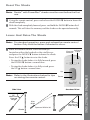
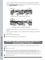
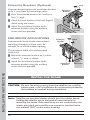
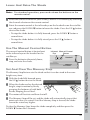
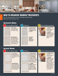
Owner’s Guide
Duette® Honeycomb Shades
™
®
PowerRise® Battery
Operated Shades
OPERATING INSTRUCTIONS
CONTENTS
Before You Begin .............................................................................................. 2
Channel Selection ............................................................................................ 2
Reset The Shade ............................................................................................... 3
Lower And Raise The Shade ............................................................................ 3
Use The Manual Control Button ..................................................................... 4
Set And Clear The Memory Stop ..................................................................... 4
Replace The Shade Batteries ............................................................................ 5
Replace The Remote Control Batteries ........................................................... 7
PowerRise® Timer (Optional) ......................................................................... 7
Troubleshooting Procedures ............................................................................ 8
Care And Cleaning ........................................................................................ 10
Installation Instructions ................................................................................11
BEFORE YOU BEGIN
OPERATING INSTRUCTIONS
Thank you for purchasing Duette® with PowerRise® battery operated shades.
Operation has been designed to be as simple as possible. Before using your
new shade, please review the instructions to acquaint yourself with all of the
procedures.
If any assistance with operation is necessary, call the Hunter Douglas Customer
Information Center at:
1-888-501-8364
Channel Selection
Duette with PowerRise shades operate on specially designated channels,
Channel 1 or Channel 2. To operate the shade, the remote control must be set
on the same channel as the shade.
Shades are set on Channel 1 unless specified for Channel 2 at the time of
ordering. When specified, for example with adjacent or stacked shades, shades
are set to Channel 2. A decal, which is visible when
CHANNEL
OPERATION
lifting the cover rail, is attached to the motor
housing and indicates Channel 2 operation.
PCN 51023480000
2
To change channel designations, refer to “Channel Selection” on page 20.
2
20M 12/96
Reset The Shade
Note: Duette® with PowerRise® shades must be reset before the first
use.
■ Using the remote control, press and release the DOWN ▼ button to lower the
shade completely.
■ With the shade completely lowered, press and hold the DOWN ▼ button for 5
seconds. This will clear the memory and the shade can be operated normally.
Lower And Raise The Shade
Note: For standard operation, press and release the remote control
button. Only hold the button if directed to do so.
■ Point the remote control at the infrared eye
located on either the headrail or the satellite eye
and press the DOWN ▼ button to lower the shade.
Press the UP ▲ button to raise the shade.
Channel
Selector
Indicator
Light
• To stop the shade before it is fully lowered, press
the DOWN ▼ button a second time.
• To stop the shade before it is fully raised, press
the UP ▲ button a second time.
Up
OPERATING INSTRUCTIONS
Note: Refer to the illustrations below for tips
on aiming the remote control.
Down
Side View
Overhead View
55º
Maximum
Upward
Angle
Shade
Aim
High
2
®
Shade
1
Operate Within 30'
45º
Maximum
Side Angle
3
Use The Manual Control Button
The manual control button is located next to the infrared eye on the headrail or
the satellite eye.
■ Pressing the button will alternately lower, stop, and raise the shade.
Infrared Manual Control
Button
Eye
Infrared
Eye
Manual Control
Button
Headrail
Satellite Eye
Set And Clear The Memory Stop
The Memory Stop feature sets the shade so that it can be raised to the same
height every time.
■ With the shade fully lowered, press the UP ▲ button to raise the shade.
OPERATING INSTRUCTIONS
■ When the shade reaches the desired height, stop its motion by firmly
grasping the bottom rail with both hands, keeping the rail level.
■ The motor will hesitate and then shut off.
■ The Memory Stop will be set, and the shade will automatically stop at that
point each time it is raised. Until the Memory Stop is cleared, the shade
cannot be raised any higher.
To clear the Memory Stop, lower the shade completely and then press the
DOWN ▼ button on the remote control for 5 seconds.
4
Replace The Shade Batteries
With normal use, the shade batteries will last a year and a half or more. Replace
them when the shade starts to operate slowly or when the shade raises to a
certain point and stops. Do not wait until the batteries completely lose power and the
shade movement stops.
Note: Only use alkaline batteries. Do not use rechargeable batteries.
Battery Wand
■ Open the front of the headrail until the cover locks into place.
Battery Wands
INSTALL THIS END
TOWARDS SPRING.
Duette® PowerRise® must be reset after
changing batteries. 1) Fully lower shade.
2) Press DOWN▼ button - Hold 5 seconds.
3) Press UP▲ button to completely raise shade.
CAUTION: TO AVOID DAMAGE, DO NOT DROP THE BATTERY WAND.
Use 8 AA alkaline batteries as shown below.
PowerRise®
To reset Silhouette® PowerRise®: 1) Fully lower
shading. 2) Tilt vanes completely open. 3) Press
DOWN▼ button - Hold 5 seconds. 4) Press UP▲
button to close and completely raise shading.
TO REPLACE BATTERIES,
REMOVE CAP FROM THIS END.
Install battery wand with label facing outward. For assistance call 1-800-327-8953.
© 1998 Hunter Douglas Inc. ® Registered trademarks of Hunter Douglas Inc.
U.S. and foreign patents pending.
2981097000 rev. 2/98
20M
AA
Removable
End Cap
AA Battery Wands Are Used On Shades Over 26" Wide
TO REPLACE BATTERIES,
REMOVE CAP FROM THIS END.
INSTALL THIS END
TOWARDS SPRING.
CAUTION: TO AVOID DAMAGE,
DO NOT DROP THE BATTERY WAND.
Use 8 AAA alkaline batteries as shown below.
Install battery wand with label facing outward.
For assistance call 1-800-327-8953.
Duette® PowerRise® must be reset after
changing batteries. 1) Fully lower shade.
2) Press DOWN▼ button - Hold 5 seconds.
3) Press UP▲ button to completely raise shade.
To reset Silhouette® PowerRise®: 1) Fully lower
shading. 2) Tilt vanes completely open.
3) Press DOWN▼ button - Hold 5 seconds.
4) Press UP▲ button to close and completely
raise shading.
PowerRise®
© 1998 Hunter Douglas Inc. ® Registered trademarks of Hunter Douglas Inc. U.S. and foreign patents pending. 2981094000 rev. 2/98 20M
Removable
End Cap
AAA
AAA Battery Wands Are Used On Shades Under 26" Wide
OPERATING INSTRUCTIONS
■ Remove the battery wand by pressing against the pivot release clip, as shown
on the next page.
■ Replace the batteries according to the instructions on the battery wand label.
■ Reinstall the wand into the headrail, as shown on the next page.
Note: The battery wand is always installed with the label facing you.
5
AA Battery Wand
Pivot
Release Clip
Spring Clip
INSTALL
TOWARD THIS END
S SPRING.
Duette ®
PowerRise
changing
®
must
be reset
2) Press batteries.
1) Fully
after
lower
3) Press DOWN▼ button
shade.
UP▲
- Hold
button
5 seconds.
to completely
To reset
raise
Silhouette
shade.
shading.
®
PowerRise
®
DOWN▼ 2) Tilt vanes
:
completely 1) Fully lower
button
button
- Hold
to close
5 seconds. open. 3)
and completely
Press
4) Press
UP▲
raise
shading.
PowerRis ®
e
BATTER
CAUTION
Y ORIENT
: TO AVOID
ATION
DAMAGE
SHOWN
, DO NOT
Use 8 AA
BELOW
. USE
DROP
alkaline batteries
THE
8 AA
BATTERY
BATTER
as shown
WAND.
IES.
Install battery
below.
USE
©
1998 Hunter
Douglas Inc.
wand with
® Registered
label facing
trademarks
of Hunter
outward.
Douglas Inc.
For assistanc
U.S. and
e call 1-800-327
foreign patents
pending.
ALKALIN
E BATTER
IES ONLY.
-8953.
2981097000
rev. 2/98
20M
TO REPLACE
BATTERI
REMOVE
ES,
CAP FROM
THIS END.
Infrared Eye On The Right Side Of The Shade
Pivot
Release Clip
Spring Clip
THIS END
INSTALLDS SPRING.
TOWAR
after
® must be reset
® PowerRise
lower shade.
Duette
1) Fully
batteries.
Hold 5 seconds.
changing
button raise shade.
DOWN▼
2) Press
to completely
UP▲ button
3) Press
lower
® : 1) Fully
® PowerRise
Press
open. 3)
Silhouette
To reset
completely
UP▲
4) Press
2) Tilt vanes
shading.
Hold 5 seconds.
button raise shading.
DOWN▼
completely
close and
button to
© 1998 Hunter
PowerR
ise
®
• For AA battery wands,
place the end of the
wand with the nonremovable end cap into
the spring clip. The
arrow on the label of the
battery wand should
point toward the spring
clip.
Douglas
Y WAND.
BATTER
DROP THE
below.
E, DO NOT
DAMAG batteries as shown
.
alkaline
N: TO AVOID
27-8953
CAUTIO
Use 8 AA
0 rev. 2/98
ce call 1-800-3
298109700
pending.
. For assistan
outward U.S. and foreign patents
Inc.
label facing
Douglas
of Hunter
wand with
trademarks
Install battery
Inc. ® Registered
20M
IES,
E BATTER
TO REPLAC FROM THIS END.
E CAP
REMOV
Infrared Eye On The Left Side Of The Shade
AAA Battery Wand
• For AAA battery wands,
place the end of the
wand with the
removable end cap into
the spring clip. The
arrow on the label of
the battery wand should
point toward the
spring clip.
Pivot
Release Clip
Spring Clip
TO REP
LAC
USE 8
CAP FRO E BATTER
AAA BATT
IES, REM
ERIES.
THIS ENDM THIS END
OVE
BATTERY USE ALKALINE
TOWARD . REINSTA
ORIENTAT
BATTERIE
LL
S SPR
S ONLY
ION:
ING.
.
REINSTAL
TO
L BATT
CLOSE
ERY
FOR ASSI WAND WITH
RAIL
LABE
STANCE
CALL 1-800 L FACING OUTW COVER:
-327-8953.
ARD.
PUSH
UP ON
LATCH
ARM
PowerR ™
ise
Infrared Eye On The Right Side Of The Shade
Spring Clip
VE
ARD.
G OUTW
ERIES, REMO L
LABEL FACIN
ACE BATT
STAL
WAND WITH 1-800-327-8953.
TO REPL THIS END. REIN
BATTERY
CALL
SPRING. REINSTALL
TANCE
CAP FROM
FOR ASSIS
TOWARDS
THIS END
USE 8 AAA
BATTERIES.
USE ALKAL
INE BATTE
RIES ONLY
TO
CLOSE
RAIL
COVER:
.
PUSH
UP ON
LATCH
ARM
PowerRise
™
OPERATING INSTRUCTIONS
Pivot
Release Clip
Infrared Eye On The Left Side Of The Shade
• Push the other end of the wand into the pivot release clip and snap
closed.
• Make sure the wand is securely seated in both the spring clip and pivot
release clip.
■ Close the cover of the headrail.
■ Allow 30 seconds for the system to power up.
6
Satellite Battery Pack (Optional)
■ Press the circular latch at the wire end of the
battery pack and lift off the cover.
■ Install the new batteries according to the
directions on the inside of the battery pack
cover.
■ Replace the cover, snapping it securely closed.
Replace The Remote Control Batteries
■ Remove the back center panel of the remote
control by pushing down on the latch and
pulling it out. Remove both AAA batteries
inside.
■ Replace the batteries with two new AAA
alkaline batteries as shown inside the remote
control.
■ Replace the back cover panel.
OPERATING INSTRUCTIONS
PowerRise® Timer (Optional)
Please refer to the PowerRise® Timer User Manual for
specific instructions on how to program and use the
timer.
Use
Tim
e
anu r
al
rM
7
TROUBLESHOOTING PROCEDURES
Problem
Symptom/Solution
• Check that the battery wand is oriented
correctly in the headrail.
• Check that the battery wand is completely
inserted in the clips and fits snugly in the
headrail.
• Check that the batteries in the wand are
installed correctly and fresh. See “Replace
the Shade Batteries” on page 5.
• Check that the AC transformer, if used, is
securely plugged into the wall outlet and that
the outlet has power. To check that the outlet
has power, plug in a lamp or device that is
known to work.
• Check that the AC transformer, if used, is
securely connected to the motor. See “Install
The AC Transformer” on page 14.
The shade operates using
the manual control button
but does not operate using
the remote control.
• Check that the correct channel is selected on
the remote. See “Channel Selection” on page 2.
• If the red light on the remote control does not
light up when the ▼/▲ buttons are pressed,
replace the batteries in the remote control. See
“Replace The Remote Control Batteries” on
page 7.
• Check that you are pointing the remote control
directly at the infrared eye. See “Lower And
Raise The Shade” on page 3. Try moving closer
to the eye. Maximum operating distance from
the remote control is 30 feet.
• Check that there are no obstructions impeding
the signal from the remote control to the
infrared eye.
• Check that there is no direct sunlight or
bright, focused light from halogen or
fluorescent light fixtures, track lighting,
spotlights, or neon lights that could be
interfering with the signal.
OPERATING INSTRUCTIONS
The shade does not
operate using either the
remote control or the
manual control button.
8
TROUBLESHOOTING PROCEDURES
Problem
Symptom/Solution
The shade does not lower
completely.
• Check for obstructions in the shade’s path.
The shade does not raise
completely.
• The Memory Stop may be activated. See “Set
And Clear The Memory Stop” on page 4.
• Check the batteries and replace if necessary.
The shade does not hang
correctly.
• Check that the mounting brackets are level.
Adjacent shades do not
stack evenly.
•
•
The shade operation is
slowing.
•
If one shade is stacking tighter than another,
it has probably been reset. Simply lower and
raise the shade to loosen the stack. The shade
stack on both shades should be within 5/16" of
each other.
For more exact stacking, use the Memory Stop
feature. See “Set And Clear The Memory Stop”
on page 4.
9
OPERATING INSTRUCTIONS
Remove the battery wand and replace the
batteries. See “Replace The Shade Batteries” on
page 5.
CARE AND CLEANING
Duette® with PowerRise® honeycomb shades are as durable as they are beautiful.
With proper installation and care, they will provide many years of beauty and
performance.
The honeycomb fabric is anti-static and dust resistant. Light dusting is all that is
generally needed to keep your shade looking like new.
CAUTION: Never submerge the headrail in any solution.
Routine Cleaning
■ Use a feather duster for regular, light dusting.
■ For more thorough dust removal, light vacuuming
using a brush attachment or hand-held vacuum with
low suction is recommended.
■ The headrail and remote control may be wiped clean
with a damp sponge and mild detergent.
Spot-Cleaning
To reduce the potential for permanent staining, spots should be cleaned as soon
as possible.
■ Use a soft cloth or sponge moistened with lukewarm water.
OPERATING INSTRUCTIONS
■ Add mild detergent if necessary.
■ Gently blot the spot. Avoid rubbing the fabric since any abrasive action may
cause it to distort.
■ Let the shade dry in the completely lowered position.
CAUTION: Do not spot-clean Batiste, Commercial, Opalessence , or
Royale fabrics.
TM
Deep Cleaning
■ Water immersion cleaning methods are not recommended for PowerRise
honeycomb shades. Do not dry clean or use injection/extraction or
ultrasonic cleaning methods with your PowerRise shades.
10
INSTALLATION INSTRUCTIONS
CONTENTS
Before You Begin .......................................................................................... 11
Materials Included ........................................................................................ 12
Tools And Supplies Needed ......................................................................... 12
Install The Battery Wand .............................................................................. 13
Install The Satellite Battery Pack Or AC Transformer (Optional) .............. 14
Mount The Installation Brackets ................................................................. 15
Inside Mount Applications .......................................................................... 16
Outside Mount Applications ........................................................................ 17
End Mount Applications .............................................................................. 18
Install The Shade .......................................................................................... 18
Remove The Shade ....................................................................................... 19
Test Operation .............................................................................................. 20
Mount The Satellite Components (Optional) .............................................. 22
BEFORE YOU BEGIN
INSTALLATION INSTRUCTIONS
Thank you for purchasing Duette® with PowerRise® battery operated shades.
Installation has been designed to be as quick and easy as possible. Before
beginning, please review the instructions to acquaint yourself with all of the
procedures.
If any assistance with installation is necessary, call the Hunter Douglas
Customer Information Center at:
1-888-501-8364
11
MATERIALS INCLUDED
Extension Brackets
(Optional)
Spacer Blocks (Optional)
Installation Brackets
Battery Wand
Duette® PowerRise® must be reset after
changing batteries. 1) Fully lower shade.
INSTALL THIS END
TOWARDS SPRING.
2) Press DOWN▼ button - Hold 5 seconds.
3) Press UP▲ button to completely raise shade.
PowerRise®
button to close and completely raise shading.
INSTALL THIS END
TOWARDS SPRING.
Satellite
Battery Pack
(Optional)
CAUTION: TO AVOID DAMAGE, DO NOT DROP THE BATTERY WAND.
Use 8 AA alkaline batteries as shown below.
TO REPLACE BATTERIES,
REMOVE CAP FROM THIS END.
To reset Silhouette® PowerRise®: 1) Fully lower
shading. 2) Tilt vanes completely open. 3) Press
DOWN▼ button - Hold 5 seconds. 4) Press UP▲
® must be reset after
Duette® PowerRise
lower shade.
changing batteries. 1) Fully
- Hold 5 seconds.
2) Press DOWN▼ button
completely raise shade.
3) Press UP▲ button to
Install battery wand with label facing outward. For assistance call 1-800-327-8953.
© 1998 Hunter Douglas Inc. ® Registered trademarks of Hunter Douglas Inc.
U.S. and foreign patents pending.
2981097000 rev. 2/98
20M
BATTERY WAND.
CAUTION: TO AVOID DAMAGE, DO NOT DROP THE
Use 8 AA alkaline batteries as shown below.
®
PowerRise
assistance call 1-800-327-8953. 2/98
Install battery wand with label facing outward. For
U.S. and foreign patents pending. 2981097000 rev.
® PowerRise® :
1) Fully lower
To reset Silhouette
open. 3) Press
shading. 2) Tilt vanes completely
seconds. 4) Press UP▲
DOWN▼ button - Hold 5
raise shading.
button to close and completely
of Hunter Douglas Inc.
© 1998 Hunter Douglas Inc. ® Registered trademarks
Infrared
Eye
Headrail
Headrail With Raised
Cover Rail
TO REPLACE BATTERIES,
REMOVE CAP FROM THIS END.
20M
Manual
Control
Button
Satellite Eye
(Optional)
End Cap
Honeycomb
Fabric
™
Bottom
Rail
Timer
(Optional)
®
INSTALLATION INSTRUCTIONS
7:10
Remote
Control
Bottom Rail
End Cap
AC Transformer
(Optional)
TOOLS AND SUPPLIES NEEDED
■
■
■
■
■
12
Measuring Tape
Carpenter’sLevel
Power Drill and Drill Bits
Screwdrivers (Flat Blade and Phillips)
Be sure the screws (included) contact wood
studs for secure mounting. Otherwise, use
fasteners such as expansion bolts, toggle bolts,
molley bolts, or anchors (not included).
INSTALL THE BATTERY WAND
Note: Only use alkaline batteries. Do not use rechargeable batteries.
■ Install the batteries according to the instructions on the battery wand label.
■ Install the wand into the headrail.
Battery Wands
INSTALL THIS END
TOWARDS SPRING.
Duette® PowerRise® must be reset after
changing batteries. 1) Fully lower shade.
2) Press DOWN▼ button - Hold 5 seconds.
3) Press UP▲ button to completely raise shade.
CAUTION: TO AVOID DAMAGE, DO NOT DROP THE BATTERY WAND.
Use 8 AA alkaline batteries as shown below.
PowerRise®
To reset Silhouette® PowerRise®: 1) Fully lower
shading. 2) Tilt vanes completely open. 3) Press
DOWN▼ button - Hold 5 seconds. 4) Press UP▲
button to close and completely raise shading.
TO REPLACE BATTERIES,
REMOVE CAP FROM THIS END.
Install battery wand with label facing outward. For assistance call 1-800-327-8953.
© 1998 Hunter Douglas Inc. ® Registered trademarks of Hunter Douglas Inc.
U.S. and foreign patents pending.
2981097000 rev. 2/98
20M
AA
Removable
End Cap
AA Battery Wands Are Used On Shades Over 26" Wide
TO REPLACE BATTERIES,
REMOVE CAP FROM THIS END.
INSTALL THIS END
TOWARDS SPRING.
Duette® PowerRise® must be reset after
changing batteries. 1) Fully lower shade.
2) Press DOWN▼ button - Hold 5 seconds.
3) Press UP▲ button to completely raise shade.
CAUTION: TO AVOID DAMAGE,
DO NOT DROP THE BATTERY WAND.
Use 8 AAA alkaline batteries as shown below.
To reset Silhouette® PowerRise®: 1) Fully lower
shading. 2) Tilt vanes completely open.
3) Press DOWN▼ button - Hold 5 seconds.
4) Press UP▲ button to close and completely
raise shading.
Install battery wand with label facing outward.
For assistance call 1-800-327-8953.
PowerRise®
© 1998 Hunter Douglas Inc. ® Registered trademarks of Hunter Douglas Inc. U.S. and foreign patents pending. 2981094000 rev. 2/98 20M
Removable
End Cap
AAA
AAA Battery Wands Are Used On Shades Under 26" Wide
Note: The battery wand is always installed with the label facing you.
Pivot
Release Clip
Spring Clip
INSTALL
TOWARD THIS END
S SPRING.
INSTALLATION INSTRUCTIONS
• For AA battery wands, place the end of the wand with the non-removable
end cap into the spring clip. The arrow on the label of the battery wand
should point toward the spring clip.
Duette ®
PowerRise
changing
®
must
be reset
2) Press batteries.
1) Fully
after
lower
3) Press DOWN▼ button
shade.
UP▲
- Hold
button
5 seconds.
to completely
To reset
raise
Silhouette
shade.
shading.
®
PowerRise
®
DOWN▼ 2) Tilt vanes
:
completely 1) Fully lower
button
button
- Hold
to close
5 seconds. open. 3)
and completely
Press
4) Press
UP▲
raise
shading.
PowerRis ®
e
BATTER
CAUTION
Y ORIENT
: TO AVOID
ATION
DAMAGE
SHOWN
, DO NOT
Use 8 AA
BELOW
. USE
DROP
alkaline batteries
THE
8 AA
BATTERY
BATTER
as shown
WAND.
IES.
Install battery
below.
USE
© 1998 Hunter
Douglas Inc.
wand with
® Registered
label facing
trademarks
of Hunter
outward.
Douglas Inc.
ALKALIN
E BATTER
For assistanc
e call 1-800-327
U.S. and
foreign patents
-8953.
pending.
2981097000
rev. 2/98
20M
IES ONLY.
TO REPLACE
BATTERI
REMOVE
ES,
CAP FROM
THIS END.
Infrared Eye On The Right Side Of The Shade
Pivot
Release Clip
Spring Clip
THIS END
INSTALLDS SPRING.
TOWAR
after
® must be reset
® PowerRise
lower shade.
Duette
1) Fully
batteries.
Hold 5 seconds.
changing
button raise shade.
DOWN▼
2) Press
to completely
UP▲ button
3) Press
lower
® : 1) Fully
® PowerRise
Press
open. 3)
Silhouette
To reset
completely
UP▲
4) Press
2) Tilt vanes
shading.
Hold 5 seconds.
button raise shading.
DOWN▼
completely
close and
button to
© 1998 Hunter
PowerR
ise
®
Douglas
Y WAND.
BATTER
DROP THE
below.
E, DO NOT
DAMAG batteries as shown
.
alkaline
N: TO AVOID
27-8953
CAUTIO
Use 8 AA
0 rev. 2/98
ce call 1-800-3
298109700
pending.
. For assistan
outward U.S. and foreign patents
Inc.
label facing
Douglas
of Hunter
wand with
trademarks
Install battery
Inc. ® Registered
20M
IES,
E BATTER
TO REPLAC FROM THIS END.
E CAP
REMOV
Infrared Eye On The Left Side Of The Shade
13
• For AAA battery wands, place the end of the wand with the removable
end cap into the spring clip. The arrow on the label of the battery wand
should point toward the spring clip.
Pivot
Release Clip
Spring Clip
TO REP
LAC
USE 8
CAP FRO E BATTER
AAA BATT
IES, REM
ERIES.
THIS ENDM THIS END
OVE
BATTERY USE ALKALINE
TOWARD . REINSTA
ORIENTAT
BATTERIE
LL
S SPR
S ONLY
ION:
ING.
.
REINSTAL
TO
L BATT
CLOSE
ERY
FOR ASSI WAND WITH
RAIL
LABE
STANCE
CALL 1-800 L FACING OUTW COVER:
-327-8953.
ARD.
PUSH
UP ON
LATCH
ARM
PowerR
ise ™
Infrared Eye On The Right Side Of The Shade
Pivot
Release Clip
Spring Clip
VE
ARD.
G OUTW
ERIES, REMO L
LABEL FACIN
ACE BATT
STAL
WAND WITH 1-800-327-8953.
TO REPL THIS END. REIN
BATTERY
CALL
SPRING. REINSTALL
TANCE
CAP FROM
FOR ASSIS
TOWARDS
THIS END
USE 8 AAA
BATTERIES.
USE ALKAL
INE BATTE
RIES ONLY
TO
CLOSE
RAIL
COVER:
.
PUSH
UP ON
LATCH
ARM
PowerRise
™
Infrared Eye On The Left Side Of The Shade
• Push the other end of the wand into the pivot release clip and snap
closed.
• Make sure the wand is securely seated in both the spring clip and pivot
release clip.
INSTALLATION INSTRUCTIONS
■ Close the cover of the headrail.
■ Allow 30 seconds for the system to power up.
INSTALL THE SATELLITE BATTERY PACK OR AC
TRANSFORMER (OPTIONAL)
If the satellite battery pack or AC transformer was ordered, connect it to the
motor.
■ Open the cover rail.
■ From the top of the headrail, insert the 2-port satellite battery pack or AC
transformer connector into the PWR plug on the motor housing, as shown
at the top of the next page. Do not force the connection. Make sure the
orientation of the plug is correct before attempting to make the connection.
■ Close the cover rail.
14
Wire From The
Limit Assembly
(DO NOT REMOVE)
Wire Carrying Power
From The Satellite
Battery Pack Or The
AC Transformer
Wire From The Internal Eye
Or Satellite Eye
MOUNT THE INSTALLATION BRACKETS
Mounting Requirements
Note: Mount the headrail level for proper shade operation. Use a
carpenter’s level to check that the mounting surface is level on
an inside mount and that the tops of the installation brackets
are level and aligned on an outside mount. If necessary, shim
the brackets.
Number of Brackets Required
■ Use spacer blocks or extension brackets for additional clearance.
Shade Width*
12"
311/8"
791/8"
1271/8"
-
31"
79"
127"
174"
Brackets Required
2
3
4
5
*End Mount Maximum Width Is 65". Two Installation Brackets And Two
Extension Brackets Are Always Necessary For End Mounting.
15
INSTALLATION INSTRUCTIONS
■ The number of installation brackets included with each shade depends upon
the ordered width, as shown in the chart below.
Bracket Spacing
■ Bracket spacing is the same for inside mounts, outside mounts, or ceiling
mounts. End mounting is explained on page 18.
■ The two end brackets are spaced so that their outside edges are at least 5/8" in
from the ends of the headrail.
Minimum Of
5
/8"
Space Evenly
Minimum Of
5
/8"
Space Evenly
Headrail
■ Additional brackets, if used, are evenly spaced between the two end brackets.
■ Adjust the bracket positions to accommodate any obstructions to the bottom
rail, such as window cranks or handles.
■ Measure and mark all bracket locations.
INSIDE MOUNT APPLICATIONS
Minimum mounting depth is 5/8".
INSTALLATION INSTRUCTIONS
Minimum
Depth
Fully
Recessed
5
/8"
5
/8"
5
/8"
See
Depth
Chart
Bracket Placement
■ The depth required to fully recess a shade depends on the pleat size.
Depth Chart For Bracket Placement
Pleat Size
16
Minimum
Fully Recessed
1/2" Standard
5/8"
3/8" Standard
5/8"
3/4" Standard
5/8"
1" Standard
Double Honeycomb
5/8"
5/8"
2 3/8"
2 3/8"
2 3/8"
Triple Honeycomb
5/8"
2 3/8"
2"
2"
STALLATION INSTRUCTIONS
Note: For optimal operation of the infrared eye, the shade should not
be recessed past the front of the window opening.
■ Place both end brackets so that their outside edges abut the marks on the
mounting surface.
■ Check that each bracket is level and aligned. Attach using two screws.
OUTSIDE MOUNT APPLICATIONS
Minimum height measurement is 3/4".
Bracket Placement
■ Center the shade over the window opening
and mark the ends of the headrail.
■ Measure a minimum of
in from
the marks on the wall and mark the
bracket locations.
5/8"
5
/8"
Minimum
Mark
On Wall
3
/4"
Minimum
■ Align both end brackets so that their
outside edges abut the marks on the
mounting.
■ Adjust the bracket position to accommodate any obstructions to the bottom
rail, such as window cranks or handles.
■ Check that each bracket is level and their tops are aligned. Attach using two
screws.
Each spacer block projects brackets 1/2"
away from the mounting surface.
■ Mount spacer blocks with the solid
side facing the mounting surface.
Spacer Blocks
/"
12
/"
12
/"
12
■ Use two mounting screws. Screws
should be long enough to secure the
bracket to the mounting surface.
■ Use a maximum of three spacer blocks per bracket.
Note: Longer screws are required to secure the spacer blocks. These
are not provided.
17
INSTALLATION INSTRUCTIONS
Spacer Blocks (Optional)
Extension Brackets (Optional)
Nuts
Extension brackets project the installation brackets
up to 3" away from the mounting surface.
Extension
Bracket
■ Place the extension brackets on a surface at
least 3/4" high.
■ Check that each bracket is level and aligned.
Attach using two screws.
■ Attach the installation brackets to the
extension brackets using the machine
screws and nuts provided.
END MOUNT APPLICATIONS
End mount the headrail when conventional
mounting techniques will not work, for
example, in an arched window opening.
Installation
Bracket
Extension
Bracket
Nuts
The maximum width of an end-mounted
shade is 65".
■ Mount the extension brackets on a surface
at least 1 1/2" wide, as shown.
INSTALLATION INSTRUCTIONS
■ Attach the installation brackets to the
extension brackets using the machine
screws and nuts provided.
Installation
Bracket
11/2"
Minimum
INSTALL THE SHADE
CAUTION: Be sure the wires coming from the satellite eye, satellite
battery pack, or AC transformer do not become pinched by
the brackets or headrail during installation.
Note: Satellite eye operated shades should have the rubber bands
holding the satellite eye to the headrail removed prior to
installing the shade. If the satellite eye is not connected to the
shade, plug the 4-wire satellite eye connector into the 4-wire
slot marked “SAT” on the motor housing.
18
■ Tip the headrail forward and fit the back bottom edge into the lower lip of
each bracket.
Bracket
Locking
Tab
Bracket
Headrail
Cover
Rail
Lower
Lip
Headrail
■ Rotate the headrail up until it snaps into the locking tab on the back of each
bracket.
REMOVE THE SHADE
There are two ways to remove the headrail
from the mounting bracket.
➀
Cover
Rail
Locking
Tab
Bracket
1) Access the locking tab through the front of
the headrail.
■
Lift the cover rail.
■
Push in on the locking tab and rotate
the headrail out of the bracket.
■
■
Insert a long, flat blade screwdriver
between the back of the installation
bracket and the headrail.
Push up on the locking tab and rotate
the headrail out of the bracket.
➁
Bracket
Locking
Tab
Headrail
19
INSTALLATION INSTRUCTIONS
2) Access the locking tab from behind the
headrail.
Headrail
To Release, Lift The Cover Rail
And Push In On The Locking Tab
TEST OPERATION
CAUTION: Duette® with PowerRise® shades must be reset before the
first use.
Channel Selection
PowerRise shades are set on Channel 1 (switch toward the front of the shade)
unless specified for Channel 2 at the time of ordering. To switch a shade’s
operating channel:
Shade Motor
■ Remove the shade from the
mounting brackets and
open the cover rail.
■ The channel selector is
located on the motor board
next to the limit assembly
plug.
Position For
Standard
PowerRise
Channel 1
Position
(Standard)
■ The right switch controls
the channel operation and
the left switch controls the shade
operation.
INSTALLATION INSTRUCTIONS
■ Using a small, flat blade screwdriver, flip the right channel selector switch
toward the front of the shade for Channel 1 operation and toward the
back of the shade for Channel 2 operation.
CAUTION: Leave the left side switch in the back position.
Channel
Selector
Reset The Shade
■ Press and release the DOWN ▼ button to
lower the shade completely.
■ With the shade completely lowered, press and
hold the DOWN ▼ button for 5 seconds. This
will clear the memory and the shade can be
operated normally.
Up
Down
20
Indicator
Light
Lower And Raise The Shade
Note: For standard operation, press and release the buttons on the
remote control.
■ Select the correct channel for your shade (Channel 1 is standard) by switching
the channel selector on the remote control.
■ Point the remote control at the infrared eye on the headrail or on the satellite
eye and press the DOWN ▼ button to lower the shade. Press the UP ▲ button
to raise the shade.
• To stop the shade before it is fully lowered, press the DOWN ▼ button a
second time.
• To stop the shade before it is fully raised, press the UP ▲ button a
second time.
Use The Manual Control Button
The manual control button is located next
to the infrared eye on the headrail or the
satellite eye.
Infrared Manual Control
Button
Eye
Headrail
■ Press the button to alternately lower,
stop, and raise the shade.
Set And Clear The Memory Stop
INSTALLATION INSTRUCTIONS
The Memory Stop feature sets the shade so that it can be raised to the same
height every time.
■ With the shade fully lowered, press
the UP ▲ button to raise the shade.
■ When the shade reaches the desired
height, stop its motion by firmly
grasping the bottom rail with both
hands, keeping the rail level.
■ The motor will hesitate and then shut off.
■ The Memory Stop will be set, and the shade will automatically stop at that
point each time it is raised. Until the Memory Stop is cleared, the shade
cannot be raised any higher.
To clear the Memory Stop, lower the shade completely and then press the
DOWN ▼ button for 5 seconds.
21
MOUNT THE SATELLITE COMPONENTS (OPTIONAL)
Optional satellite components consist of the satellite battery pack, the satellite
eye, or the AC transformer.
Satellite Battery Pack
■ Determine where to mount the satellite battery pack.
Outside Mount
• Mount the satellite battery pack in a location
where it will not interfere with the shade’s
operation.
• On outside mounts, the wire will exit from the
top of the shade.
• On inside mounts, the wire will run along the
control side end cap to the front of the shade.
■ Mount the satellite battery pack.
• Use the holes in the rear of the pack as a
template to mark the screw locations on the
mounting surface.
Inside Mount
• Attach using two screws.
INSTALLATION INSTRUCTIONS
■ Load batteries into the satellite battery pack.
• After attaching the satellite battery pack to the
mounting surface, load in eight AA alkaline
batteries, according to the instructions on the
battery pack.
Satellite Eye
CAUTION: Handle the satellite eye carefully to avoid damaging the
infrared eye. Do not touch or push on the infrared eye.
22
■ Determine where to mount the satellite eye.
• Choose a location for the satellite
eye where the signal from the
remote is not obstructed. Do not
mount the satellite eye in direct
sunlight or bright, focused light
from halogen or fluorescent light
fixtures, track lighting, spotlights,
or neon lights.
Satellite Eye Mounting Options
Outside Mount
• Check that the wire is not caught or
pinched in the brackets or headrail.
• With inside mounts, wrap the wire
behind the headrail and along the
side of the end cap to the front of
the shade.
Inside Mount
■ Mount the satellite eye.
Wall
• Flip the satellite eye down and place the
hinged flange against the wall. Attach the
flange to the wall with a single screw.
• Swivel the satellite eye upward to the
correct angle for receiving the signal
from the remote control.
INSTALLATION INSTRUCTIONS
AC Transformer
■ Plug the AC transformer into a standard 110V outlet.
• Route the wire to a location where it will not interfere with
the shade.
• On outside mounts, the wire exits from the top of the shade.
P/N # 298119800
AC-DC Adaptor
MODEL: MKD-48121000
INPUT: 120V AC 60 Hz 0.3A
OUTPUT: 12V DC 100 mA
Listed
• On inside mounts, the wire runs along the control side end
cap to the front of the shade.
• After the AC transformer
has been attached to the
2-pin power connector on
the headrail, and the
headrail has been installed,
plug the AC transformer
into a 110V outlet.
Outside Mount
Inside Mount
23
Questions? Call the
Hunter Douglas
Customer Information Center at
1-888-501-8364
INSTALLATION INSTRUCTIONS
Visit our Web site at hunterdouglas.com
© 2003, 2004 Hunter Douglas Inc. ® Registered trademark of Hunter Douglas Inc. ™Trademark of Hunter Douglas Inc.
Patented in the U.S. and foreign countries. U.S. and foreign patents pending.
PCN 5109080000
24
rev. 8/04