1
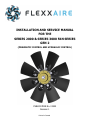
INSTALLATION AND SERVICE MANUAL
FOR THE
SERIES 2000 & SERIES 3000 FAN SERIES
GEN 2
(PNEUMATIC CONTROL AND HYDRAULIC CONTROL)
PUBLICATION No. 01900
Revision 1
Printed in Canada
1.1
INTRODUCTION
1.2.1
Thank you for purchasing a Flexxaire Fan System.
Flexxaire takes great pride in designing, manufacturing
and assembling its products for many years of use.
This manual (P/N 01900) is produced to assist in the installation, operation and maintenance of the GEN 2 Flexxaire® Series 2000 and Series 3000 Fan Systems using
Pneumatic or Hydraulic actuation.
Flexxaire has made every effort to ensure that the information contained in this manual is correct and complete at
the time of printing. Flexxaire will assume no responsibility
for any errors or omissions. If you have any questions
regarding this manual, any other document provided with
your fan system or any questions not answered by this
manual, please contact:
Flexxaire Inc.
PROTECTIVE EQUIPMENT
Always wear protective glasses, protective shoes and any
other protective equipment as required by law and/or
your company safety program.
1.2.2
PRESSURIZED FAN HUB
The hub assembly is spring loaded. If disassembly of the
hub is required, take caution that you are well protected
from the hub’s release which may be sudden and pose an
impact related injury.
Also make sure that the internal pressure is released.
Consult the pneumatic or hydraulic control instructions in
this manual.
1.2.3
HOT FLUIDS AND PARTS
To avoid burns, be alert for hot parts on the assembly or
the machine that have just been stopped and have hot
fluid in lines, tubes and compartments.
Product Support Department
10430-180 Street
Edmonton, Alberta, Canada
T5S-1C3
1.3
Phone: 780-483-3267
Fax: 780-483-6099
Monday to Friday 7:00 am to 3:30 pm MST
1.2
The following needs to be considered prior to the installation of the Flexxaire Fan System. If your situation is listed
in this section, DO NOT INSTALL THE FAN. Damage
and/or injury may occur.
1.3.1
IMPORTANT SAFETY INFORMATION
FAN SPECIFICATIONS
MOUNTING
The safety information in this publication is to be used in
conjunction with the safety information supplied from the
original machine manufacturer. Please refer to all safety
information supplied, prior to doing any work on the fan
assembly or any other component to assure safety.
WARNING: This fan is not designed to be mounted onto
a crank shaft or crank shaft pulley. Torsional vibration
from crankshafts will damage the fan and could result in
machine damage and serious injury.
Improper operation, maintenance or repair of this
product can be dangerous and could result in injury
or death.
1.3.2
Always use Genuine Flexxaire parts and components or
Flexxaire approved parts and components. The use of unapproved parts and/or components will void the 1-year
warranty.
Do not operate or perform any maintenance on this
product until you have read and understand the operation and maintenance information. Please contact Flexxaire or an approved dealer for any information that you may require.
The person(s) servicing the product may be unfamiliar with many of the systems or components on
the product. It is important to use caution when
performing any type of service work. Knowledge of
the product and/or its components is important before the removal or disassembly of any component.
Flexxaire.com
FAN BLADE TIP SPEED
WARNING: The fan system must not exceed a blade tip
speed of 20,000 feet/minute. Exceeding this speed may
cause damage to and/or failure of the fan, which in turn
may cause injury or death, or damage to the radiator and
surrounding equipment.
To calculate the blade tip speed, use the following formula:
Fan Diameter (Inches) X 3.14 X Fan RPM
12
If your calculated tip speed exceeds 20,000 ft/min, contact Flexxaire directly, prior to installation. It is important to use Fan RPM and NOT engine RPM.
01900r1
Page 1 of 10
1.4
FAN OVERVIEW
Flexxaire’s Series 2000/3000 fan systems are designed
to minimize overheating caused by debris plugged radiators, screens and guards, and reduce overcooling in low
ambient temperatures. The blades of the Series 2000/
Series 3000 vary pitch, not speed, to control air flow
volume and direction.
How your Series 2000/Series 3000 works:
The Series 2000/Series 3000 can be purchased as a pneumatically actuated variable pitch fan or hydraulically actuated variable pitch fan. The blades are held in full pitch by
a heavy spring. As pneumatic (or hydraulic) pressure is
applied to the control line, the pitch of the blade is reduced
and then reversed. When the pressure is released, the fan
blades return to their default position.
2.0
The Series 2000/Series 3000 fan has a number of important features:
1.
Fail Safe Operation: The blades are spring loaded
into the default full pitch position. If the fan loses
pressure, the fan will default to full pitch and act
like a fixed pitch fan giving maximum cooling.
2.
Depending on the control kit ordered (see Section
2.0), the fan can be run in a neutral pitch (or any
pitch in between) to solve overcooling problems
and save horsepower and fuel.
3.
When purging, there are no horsepower spikes, in
fact, the horsepower drops off as you pass
through neutral pitch, then slowly builds as pitch
increases.
HYDRAULIC CONTROL:
CONTROL KITS
Due to the variability of machines that the Series 2000/
Series 3000 fan may be installed on, the fan does not include any control components. Flexxaire has a number of
different control kits available to suit a wide range of applications:
- 2 Position kit (Manual Purge)
- 2 Position kit with timer (Manual and Auto Purge)
- Infinitely Variable Pitch Controller (IVP fan control)
- Available in 12V and 24V configurations
PNEUMATIC CONTROL:
- 2 Position kit (Manual Purge)
Contact Flexxaire or your dealer for details and
availability.
- 2 Position kit with timer (Manual and Auto Purge)
- Infinitely Variable Pitch Controller (IVP fan control)
- Each kit is available with or without an air compressor
- Available in 12V and 24V configurations
Flexxaire.com
01900r1
Page 2 of 10
2.1
MAJOR COMPONENTS
The Series 2000/Series 3000 Fan Assembly can be identified by several external components as shown in Figure 1. Use
this diagram for terminology and major component identification. (This figure is of a Series 2000 Hydraulic, but all the
major components are the same between the Series 2000 and Series 3000 fans.)
Figure 1
MAJOR COMPONENTS:
1. Blade Assembly
4. Mounting Adapter Bolts
7. Blade Counter Weight
2. Rotary Union
5. Mounting Adapter
8. Blade Mounting Shaft
3. Hub Assembly
6. Hub Mounting Bolts
9. Fan Pilot
2.2
EXISTING FAN REMOVAL
2.3
INSTALLATION
The following is a general description for the removal of an
existing fan and the installation of a Flexxaire Series 2000/
Series 3000 Fan.
2.3.1
Mounting Adapters
1.
Remove fan guards and safety equipment to gain
access to the existing fan.
2.
Loosen belt(s) and remove existing fan hardware
as required.
For some applications, a wider 2-piece adapter may be
used, and the necessary hardware for assembling the 2
parts together will be included. This 2-piece adapter may
be pre-assembled.
3.
Clean mounting surface of the fan drive.
Flexxaire.com
The Series 2000/Series 3000 fan is supplied with a premachined mounting adapter plate. Pre-machined mounting adapters are machined for your pilot and bolt circle.
01900r1
Page 3 of 10
2.3.2
Fan Position
Ideally the fan should be centered in the shroud (30-70%
immersion is acceptable). This may require modification or
removal of the fan spacer or modification of the shroud.
See Figure 2.
2. Set up dial gauge to measure axial deviation of the
mounting adapter on the fan mounting surface.
Devia tion
should
not
exceed
0.005”.
Refer to Figure 3.
3. Set up dial gauge to measure radial deviation of the
mounting adapter on the 1” pilot hole surface. Deviation
should
not
exceed
0.005”.
Refer to Figure 3.
4. Remove the shipping plug from the rear of the fan.
Place the Series 2000/Series 3000 fan onto the
mounting adapter and torque the 3/8” bolts to 30 Ft
-Lbs (41 N.m).
Do not use loctite.
Refer to Figure 4.
Figure 2
1. Install the Flexxaire supplied mounting adapter using
bolts from the original fan. If the bolt length needs
to be changed, use an equivalent or better grade of
bolt.
Follow original equipment manufacturer’s
torque and thread locking specifications when installing the mounting adapter to the fan drive. Refer
to Figure 3.
Figure 4
3.0
ATTACHING THE BLADES
Your Flexxaire fan shipped with the fan blades unattached. Care must be taken to ensure the blades are
attached correctly.
If the primary operation of the fan is to “pull” air towards the engine, the blades must be mounted with
the concave surface towards the engine (assuming the
fan rotates counter clockwise, as viewed from the engine towards the fan).
If the primary operation of the fan is to “push” air
away from the engine, the blades must be mounted
with the concave surface away from the engine. Refer
to Figure 5. (Some fans are shipped from Flexxaire
with the blades already attached, by special order.)
Figure 3
Flexxaire.com
01900r1
Page 4 of 10
2.
Insert the ¼” NC short bolts through the upper
holes in the blade caps and blades. Tighten the
assembly to the blade shaft and the blade. Regular hex head bolts with washers may be substituted for the flange headed bolts.
3.
Carefully torque the blade bolts with a certified
torque wrench to the following specification:
¼”–20NC to 9 ft./lbs
WARNING – DO NOT OVER TORQUE
NOTE: If any of the supplied flanged lock nuts are lost,
they may be replaced with grade 8 flanged lock nuts.
Loctite 242 or equivalent must be applied to the
bolt if lock nuts are not used.
Figure 5
1.
4.
If only one counterweight is supplied, then the
counterweight can be installed on either side, as
long as they are all on the same side.
Rotate the fan by hand and check for obstructtions. A final check will be required once the
pneumatic or hydraulic hose has been connected
to the fan. (See Page 7 for a list of required pressures for each fan model.) Spin the fan by hand
with the blade pitch reversed and check for obstructions.
5.
Insert the supplied ¼”NC long hex bolt through
the counterweight then the lower hole in the blade
or cap. The head of the bolt should be on the side
with the counterweight when only one counter
weight is being used. Tighten the assembly with
the supplied ¼”NC lock nut. See Figure 6.
Ensure you have the correct blade clearance. See
Figure 7 on the next page or a list of recommended minimum clearances based on fan diamter.
6.
Tighten the fan belts and replace all the fan
guards and safety equipment.
7.
Attach the “WARNING” label to the machine, on a
housing, guard, or any location near the fan
where it can be easily seen.
Series 2000/Series 3000 fans are supplied with
either 1 or 2 counterweights per blade. If two
counter weights per blade are supplied, install one
weight on each side.
WARNING: Failure to have the correct blade clearance could result in blade contact that can cause extensive damage to people and equipment.
Figure 6
Flexxaire.com
01900r1
Page 5 of 10
Figure 7
3.1
Series 3000 AIR DAM
Series 3000 fans above 54” in diameter have extended blade shafts, and an aluminum air dam/air seal is mounted to
the front of the hub. This air dam is necessary to prevent reverse airflow between the bottom of the blades and the hub
diameter.
The air dam is mounted with 5 bolts, on the front shoulder of the Series 3000 hub assembly.
See Figures 8 and 9.
Figure 9
Figure 8
Flexxaire.com
01900r1
Page 6 of 10
4.0
PNEUMATIC SPECIFICATIONS
5.0
Flexxaire supplies a number of pneumatic control options,
but the Series 2000/ Series 3000 Pneumatic versions can
be operated using any air source that meets the general
specifications listed below. If your machine has air on
board then this source will be available. If not, then a
compressor kit will be required.
Series 2000 Pneumatic General Specifications:
Full Pitch (default position):
0 psi
Neutral Pitch (Stop air position):
75 psi
Reverse Pitch (Purge position):
98 psi
Max continuous pressure:
120 psi
(extended operation at higher pressure will reduce the life
of the rotary union seal).
Series 3000 Pneumatic General Specifications:
Full Pitch (default position):
0 psi
Neutral Pitch (Stop air position):
45 psi
Reverse Pitch (Purge position):
57 psi
Max continuous pressure:
120psi
Recommended minimum flow rate: .35cfm @ 70 psi.
(The lower the flow rate, the longer it takes to purge the
fan. –at .35cfm @ 70psi it takes approximately 7 seconds
to fully reverse pitch).
4.1
PNEUMATIC LINE INSTALL
1.
Drill a hole in your fan shroud to allow the flexible
hose to be routed into the engine compartment.
Secure the hose using hose clamps or tie wraps.
Be sure that the air line is properly secured so it
cannot interfere with the fan blades.
2.
Attach the incoming air line to the push-in fitting
on the front of the fan. If you did not purchase
one of Flexxaire’s control kits you will need to
source flexible hose and fittings that will attach to
the 1/8-NPT female fitting on the front of the fan.
The hose should be robust enough to withstand
abrasion from air flow, and temperature and vibration inherent from engines. Failure of the hose
could lead to fan damage if the hose comes in
contact with the blades.
WARNING: Do not secure the air lines in any way that
will cause leverage to be applied to the rotary union.
Failure of the rotary union could result.
Flexxaire.com
HYDRAULIC SPECIFICATIONS
Flexxaire supplies a number of hydraulic control options,
but the Series 2000/Series 3000 Hydraulic versions can be
operated using any hydraulic source that meets the general specifications listed below. If your machine has hydraulics on board then this source should be available.
Series 2000 Hydraulic General Specifications:
Full Pitch (default position):
0 psi
Neutral Pitch (Stop air position):
100 psi
Reverse Pitch (Purge position):
180psi
Maximum continuous pressure:
500 psi
Series 2000 High Pressure Hydraulic General Specifications:
Full Pitch (default position):
0 psi
Neutral Pitch (Stop air position):
310 psi
Reverse Pitch (Purge position):
460 psi
Maximum continuous pressure:
950 psi
Series 3000 Hydraulic General Specifications:
Full Pitch (default position):
0 psi
Neutral Pitch (Stop air position):
190 psi
Reverse Pitch (Purge position):
300 psi
Maximum continuous pressure:
500 psi
5.1
HYDRAULIC LINE INSTALL
1.
Drill a hole in your fan shroud to allow the flexible
hose to be routed into the engine compartment.
Secure the hose using hose clamps.
2.
No exterior bracing should be used to prevent the
rotary union from rotating. It is imperative that a
flexible connection be used. DO NOT PIPE SOLID.
3.
Ensure that the hose clears all parts of the fan. If
possible, secure the hose away from the fan.
Common ways to do this are zip tie the hose to
the radiator core, or to attach it to the radiator
frame or the bolted flanges between the radiator
cores.
WARNING: Do not secure the hydraulic hose so tight as
to cause a side load on the rotary union. Failure of the
bearings could result.
01900r1
Page 7 of 10
WARNING: Do not secure the hydraulic hose so loose
that the hose could contact the blades due to sudden air
reversal, vibration, etc….
from time to time to safeguard against fan blade damage
which could lead to equipment downtime and/or other
damages.
WARNING: Ensure that you have the minimum clearance
between the rotary union and closest obstruction as per
Figure 7 on page 6.
6.2
4.
5.2
The fan is shipped with a default hose assembly
attached to the hub assembly. Contact Flexxaire if
you want a different hose length of different fit
tings for future orders. The hose is attached at
the Flexxaire factory to avoid unnecessary side
loads to the bearings of the rotary union that can
be applied every time the hose is attached or detached from the rotary union.
1. Ensure that the fan fully reverses pitch.
2. Check for leaks in the rotary union.
3. Check that the rotary union bearings rotate smoothly.
4. Verify that you have the correct blade clearance as
per Figure 7 on page 6.
6.3
HYDRAULIC LINE SPECIFICATIONS
Series 2000
1.
2.
3.
The connection on the rotary union is a 1/8NPT
female thread.
The fitting on the end of the default hose is a male
1/8NPT. An adapter is used to mate to the #6 ORB
port on the manifold.
If supplying your own hose, it is recommended to
use a hose that is as small as possible. The potential exists that a large, heavy hose with bulky fit
tings could create a side load on the rotary union,
just due to the weight of the hose. Side loads can
drastically reduce the life of the rotary union.
4.
Series 3000
1.
The connection on the rotary union is a 1/8NPT
female thread.
2.
The fitting on the end of the default hose is a flare
37 deg #4. An adapter is used to mate to the #6
ORB port on the manifold.
3.
If supplying your own hose, it is recommended to
use a hose that is minimum ¼” inside diameter.
Smaller hoses can cause a problem with the fan
performance as the small hose will slow down the
actuation speed of the fan blades while changing
pitch or purging.
4.
6.0
SERVICE AND MAINTENANCE
Flexxaire’s Series 2000/Series 3000 fan hub is fully sealed
with o-rings, and contains a small amount of oil. As a result, the fan should not require any maintenance.
6.1
VISUAL INSPECTIONS
Under normal operating conditions, Series 2000/ Series
3000 fans do not require any scheduled maintenance and
are built to provide thousands of hours of trouble free service. In moderate to extreme operating conditions a visual inspection of the moving parts is recommended
Flexxaire.com
MECHANICAL REVIEW
01900r1
INSTALL CHECK LIST
CHECK
YES
NO
Does fan rotate in default
and full reverse pitches
without obstruction?
□
□
Are blade fasteners
torqued to 9 ft-lbs
□
□
Are blades installed in the
correct orientation
(blower /sucker)? See Fig
5, page 5
□
□
Has the side load on the
pressure line been minimized?
□
□
Has the pressure line been
constrained to prevent
contact with the blades?
□
□
Is the pressure line flexible
enough to accommodate
relative movement between the radiator and
engine?
□
□
Are any of the blades
damaged?
□
□
Does the rotary union rotate freely?
□
□
Are there any pressure
leaks in the system?
□
□
Are all screens and guards
secured?
□
□
□
□
Have you recorded the fan
S/N for future reference?
S/N_______________
Page 8 of 10
6.4
ROTARY UNION
The rotary union used in the fan hub is lubricated for life
and requires no additional maintenance other than periodic
inspection to determine if normal wear has caused the union to leak.
A locking ring is used to lock the rotary union into the fan
system.
In addition, some fans are supplied with a Pitch Sensor or
are Pitch Sensor Ready. These fans have a pin installed
internally in the piston that travels through rotary union
when installed. A jig is supplied with rotary union to verify
pin center for applicable models. If your design does have
the internal pin, please refer to Section 6.4.3 for proper
use of jig.
6.4.1
ROTARY UNION REPLACEMENT
Flexxaire.com
Figure 12
Figure 10
Figure 13
Figure 11
Figure 14
01900r1
Page 9 of 10
Figure 15
6.4.3
INTERNAL PIN VERIFICATION FOR PITCH
SENSOR ENABLED/PITCH SENSOR READY
FANS
Figure 16
Figure 17
Flexxaire.com
01900r1
Page 10 of 10