1
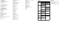
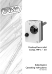
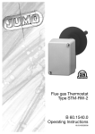
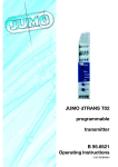
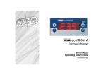
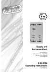
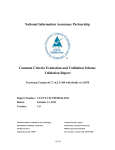
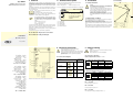
Type 402004
Multiple-range pressure and
differential pressure transmitter
1 General
2 Technical Description
3 Installation
JUMO GmbH & Co. KG is a DIN ISO 9001 certified company. The pressure transmitter described below meets the requirements according to
DIN and VDE. You have purchased a product that satisfies even very
stringent requirements and meets or even exceeds all the given specifications.
Should there nonetheless be any reason for dissatisfaction, please send
the instrument back to us with as detailed a description as possible of
the shortcoming found.
Should you require detailed technical data about the instrument,
please ask for the data sheet 40.2004.
Internet: www.jumo.net
Telephone (06 61) 60 03-7 15
3.1 Safety instruction
Made in Germany
TYP 402004
(1)
(2)
(3)
This operating manual also contains assembly instructions for the pressure transmitter. Should there still be
any difficulties at the time of commissioning or during
use please contact your local JUMO branch or JUMO
Fulda.
Telephone:(06 61) 60 03-7 15
Fax:
(06 61) 60 03-6 06
Internet: www.jumo.net
The pressure transmitter described in this operating manual is maintenance-free. It does not contain any components that can be repaired or
replaced by you. Repairs can be carried out only at the factory!
Installation, commissioning and operation can only be done by trained
technical persons.
The instrument may only be used within its specifications.
Caution
The instrument does not conform to the requirements
"Plant component with safety function“ according to the
Pressurized Devices Directive 97/23/EC.
In the case of dangerous measurement media, such as oxygen, acetylene, flammable and poisonous materials, as
well as refrigeration equipment, pressurized tanks etc, the
relevant existing specifications must be met!
Ignoring these specifications and regulations can result in
injuries to persons and damage to property.
Only suitably qualified personnel may work on these instruments.
You can see the model of your pressure transmitter from the type plate.
Please read the operating manual before you commission the device.
We reserve the right to make technical changes.
Please help us to improve this operating manual; we
would be grateful for your suggestions.
Ser. Nr.
Pmax
(4)
(5)
(1)
Pressure inlet
(2)
Output signal
(3)
Voltage supply
(4)
Series number
(5)
Maximum pressure
: 0...250/ 500/ 1500/ 3000 Pa
: 0...010 V/ 0 (4)...20 mA
: 19...31 VDC / 19...25 VAC
: 45642900033907ARo
: 200 hPa
3.3 Fastening
The instrument is suitable for the acquisition of overpressure, underpressure or differential pressure of non-aggresive gases
The instrument must not be installed in the vicinity of sources of noise
(transformers, transmitters, electrical motors) and heat.
Shocks or vibrations at the installation site can result in measurement errors.
The instrument was set with an ambient temperature of 20°C, vertically
with the pressure connection downwards. Deviations from this installation position and ambient temperature result in measurement errors.
B 40.2004.0
Operating manual
11.07/00502829
t
5 Commissioning
Pressure transmitters may only be connected by
suitably qualified technical personnel!
Please comply with the specifications and safety regulations
for electrical, light current and heavy current systems, and especially the country-specific specifications applicable
(e.g. VDE 0100).
(1)
Caution
Jumper J1 must not be reconnected elsewhere and must
remain in position 2-3.
The potentiometer TP1 must not be adjusted
5.1 Pressure connection
4.1 Connection diagram
Positive overpressure at the "+“ terminal
Negative overpressure (underpressure) at "-“ terminal
Connection layout
Terminal block
J2
LL+
JUMO Process Control, Inc.
8 Technology Boulevard
Canastota, NY 13032, USA
Phone: 315-697-JUMO
1-800-554-JUMO
Fax:
315-697-5867
e-mail: [email protected]
Internet: www.jumo.us
J1
JUMO Instrument Co. Ltd.
JUMO House
Temple Bank, Riverway
Harlow, Essex CM 20 2 TT, UK
Phone: +44 1279 635533
Fax:
+44 1279 635262
e-mail: [email protected]
Internet: www.jumo.co.uk
(1)
Switch 1
5
4
Voltage supply
19 ... 25 V AC
N
L1
5
4
Output
0 ... 10 V
+
1
3
Output
0(4) ...20 mA, three-wire
+
1
2
ON
OFF
S2
Voltage supply
19 ... 31 V DC
5.2 Setting the measurement range
S1
Connection
J3
Switch 2
MEASUREMENT
RANGE
ON
ON
3000 Pa
ON
OFF
1500 Pa
OFF
ON
500 Pa
OFF
OFF
250 Pa
5.3 Setting the time constant
In order to get a stable signal even with greatly varying pressure, the time
constant can be set with the DIP switches 3 and 4.
Switch 3
Switch 4
Time constant
S4
S3
ON
OFF
✱ Fasten the instrument with 2 screws to the fastening holes (1).
(2)
3.2 Deployment conditions
Do not blow into the pressure connections.
The instrument could get damaged.
4 Electrical connection
(1)
ON
ON
ON
OFF
approx. 30 ms
4s
OFF
ON
2s
OFF
OFF
approx. 30 ms
6 Setting the output signal
6.1 0 ...20 mA
✱ Insert jumper J3 in position 2-3.
6.2 4 ...20 mA
✱ Insert jumper J3 in position 1-2.
6.3 0 ...10 mA
The voltage signal is always available (terminals 1 - 3).
✱ Unscrew the four screws (1) and remove the cover (2) of
the instrument.
JUMO GmbH & Co. KG
Street address:
Moritz-Juchheim-Straße 1
36039 Fulda, Germany
Delivery address:
Mackenrodtstraße 14
36039 Fulda, Germany
Postal address:
36035 Fulda, Germany
Phone: +49 661 6003-0
Fax:
+49 661 6003-500
e-mail: [email protected]
Internet: www.jumo.net
7 Calibrate
7.1 Setting the zero point
✱
✱
✱
✱
Remove the pressure pipes from the instrument.
Open the instrument.
Insert jumper J2 in position 2-3.
Press the T key.
7.2 Set the final value
✱ Supply the corresponding rated pressure to
the instrument through the pressure pipes.
✱ Open the instrument.
✱ Insert jumper J2 in position 1-2.
✱ Press the T key.
✱ Insert jumper J2 again in position 2-3.
8 Technical Data
Reference conditions
in accordance with DIN 16 086 and DIN IEC 770/5.3
Measurement ranges
adjustable via DIP-switches:
0 ... 250 Pa
0 ... 500 Pa
0 ... 1500 Pa
0 ... 3000 Pa
Overload limit
In case of relative pressure measurement :
10 times the final measurement value.
For measurement range 0 ... 3000 Pa:
5 times the final measurement value at
Influence of the working resistance
For output voltage:
RL ≥ 2 kΩ
For output current:
RL ≤ 500 Ω
Influence of ambient temperature
in the range +10...+50°C
(compensated temperature range)
Zero point:
≤0.12%/K
Measurement spread:≤0.12%/K
Characteristic curve
linear
Characteristic curve deviation
≤ ± 2% v. EW
(limit point setting)
Hysteresis
≤ ± 0.2% v. EW
Setting time/ Filtering time
adjustable to 30 ms or 2 s or 4 s
Stability per year
± 2%
Voltage supply
DC 19 ... 31 V or
AC 19 ... 25
9 Fault
Type of fault
Mechanical vibrations
maximum 5 g at 15 ... 2000 Hz
Degree of protection
IP 54 according to EN 60 529
No output signal
Housing
ABS
Nominal position
vertical ⊥
Weight
approx. 170 kg
Max. current drawn
≤ 20 mA (without load)
Bursting pressure
300 hPa
Permissible ambient temperature
+10...+50°C
Parts coming in contact with the pressure medium
Al, Au, Ni, Ni-Co-steel, glass, PEI, PU,
silicon
Bearing temperature
-10...+70°C
Permissible medium temperature
+10 ... +50°C
Electromagnetic compatibility
EN 61 326
Noise transmission:Class B
Possible cause
Measure
No supply voltage
Check the supply voltage
No input pressure
Check measurement medium connection
Fault at the pressure transmitter owing to impermisSend the transmitter with a
sible usage conditions
description of the fault to
Measurement system of
the supplier
the instrument faulty damaged by overpressure
Process connection
ø 6.6 x 10 mm
(for flexible hoses ø 6 mm)
Electrical connection
Terminal screws on the inside,
for conductor cross-sections up to 1.5 mm2
10 Service
Cable rupture, wrong con- Check the connections of
nections
the conductors
Output signal constant even when
there is a change
in pressure
Output signal of the pressure transmitter gets falsified owing to overvoltage
from the current limiter
Measurement point is
blocked
Provide the correct voltage
supply
Measurement range too
small – send transmitter
with description of fault to
the supplier
Check the measurement
point and clean or replace
if required
Selected measurement
range is too small
Output signal is
too high
Residual ripple
≤ 60 mV
Influence of voltage supply
In the range from 19 ... 31 V DC:
≤0.05%
see the ordering data
Mechanical shock
10 g/0.1 ms
Output signal
can be toggled with coding:
0 ... 10 V or 0 ... 20 mA
Maximum system pressure
200 hPa
Output
Resistance to jamming/noise:Industrial requirements
Output signal is
too low
Send the transmitter with a
The electronics of the
description of the fault to
pressure transmitter is
the supplier
faulty or the supply voltage
is too high
In case of output current
signal: Load is too big
In case of output voltage
signal: Load is too small
Change the impedance of
the measurement circuit
Supply voltage is too low
Change the supply voltage
Pressure transmitter setZero-point of the ting has been disturbed by
output signal is er- impermissible usage conditions (for example, overroneous
Send the transmitter with a
pressure)
description of the fault to
Pressure transmitter set- the supplier
Characteristic
ting has been disturbed by
curve of the outimpermissible usage conput signal is not
ditions (for example, overlinear
pressure)
✱ JUMO pressure recorders and pressure transmitters are
maintenance-free.
✱ In case of faults, no components or assemblies can be replaced
or repaired at the customer site.
Please send the instrument with as detailed a description as possible
of the fault to the supplier.
✱ We recommend calibrating the pressure transmitter annually.