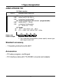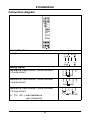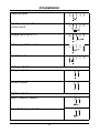
1
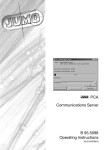
JUMO dTRANS T02
programmable
transmitter
B 95.6521
Operating Instructions
5.00/00380664
Overview of operation
1 Type designation
JUMO dTRANS T02
(1) Basic version
956521
x
x
x
x
x
x
programmable transmitter
(2) Input (programmable)
888
factory-set (Pt100 DIN vl)
999
customized configuration1
(3) Output (proportional DC current - programmable)
888
factory-set (0 — 20mA)
999
customized configuration
(4 — 20mA or 0 — 10V)
(4) Supply
22
20 — 53V AC/DC, 48 — 63Hz
23
110 — 240V +10/-15% AC, 48 — 63Hz
(1)
Order code
Order example
(2)
/
(3)
-
(4)
-
956521 / 888 - 888 - 23
1. For customized configuration, please specify sensor type
and range in plain text
Standard accessory
- 1 Operating Instructions 95.6521
Accessories
- PC setup program, multilingual
- PC interface cable with TTL/RS232 converter and adapter
1
2 Installation
Connection diagram
Connection for
Supply
Analog inputs
Resistance thermometer / potentiometer
in 4-wire circuit
Resistance thermometer / potentiometer
in 3-wire circuit
Resistance thermometer / potentiometer
in 2-wire circuit
RL ≤ 15Ω (RL = lead resistance
per conductor)
2
2 Installation
Thermocouple
Resistance transmitters in
3-wire circuit
Voltage input up to 1V
Voltage input 1V and above
Current input
Analog outputs
Voltage output
Current output
Digital outputs
Open-Collector output 1
Open-Collector output 2
3
2 Installation
Installation notes
!
The choice of cable, the installation and the electrical connection must conform to the requirements of VDE 0100 “Regulations on the Installation of Power Circuits with nominal voltages
below 1000V”, or the appropriate local regulations.
!
The electrical connection, as well as work inside the instrument,
must only be carried out by properly qualified personnel.
!
Ensure that the instrument is completely isolated from the supply before carrying out work where live components may be
touched.
!
A current limiting resistor (safety function) interrupts the supply
circuit in the transmitter in the event of a short-circuit. The external fuse of the supply should not be rated above 1A (slow).
!
Avoid magnetic or electric fields, such as caused by transformers, mobile phones or electrostatic discharge, in the neighborhood of the instrument1.
!
Do not install inductive loads (relays, solenoid valves etc.) in the
vicinity of the instrument; use RC networks, spark quenchers or
freewheel diodes for interference suppression.
!
Run input, output and supply lines separately, and not parallel
to each other. Route cable pairs close together and twisted, if
possible.
!
Sensor lines must be twisted and shielded. Do not run them
close to current-carrying components or cables. Earth the
shielding at one end on the instrument.
!
Do not connect any additional loads to the supply terminals of
the instrument.
!
The instrument is not suitable for operation in areas with an explosion hazard.
4
2 Installation
!
An electrical connection which deviates from the connection diagram may result in the destruction of the instrument.
!
If the mains supply is subject to interference (e. g. thyristor controls), the instrument should be supplied via a isolating transformer.
!
Supply fluctuations are only permissible within the specified
tolerances1.
1. see Data Sheet
Dimensions
5
3 Displays and controls
interface for
PC setup program
LEDs for operational status
sockets for measuring
the output signal
push-buttons for operating
the parameter level
Operational status at the
operating level
(normal operation)
Illumination/blink behavior
Limit comparator
1 inactive
2 inactive
Limit comparator
1 active
2 inactive
Limit comparator
1 inactive
2 active
Limit comparator
1 active
2 active
Overrange
6
3 Displays and controls
Operational status at the
parameter level
(programming mode)
Illumination/blink behavior
Limit for
limit comparator 1
Limit for
limit comparator 2
Fine calibration
(zero point)
Fine calibration (full scale)
Teach-in
(0 % value)
Differentiation of the operational states
- In the Operating level status, the power LED
is on permanently.
- In the Parameter level status, the power LED
blinks (equally on and off).
7
4 Functions and operation
You can operate the transmitter by using the “Span” and “Zero”
push-buttons in conjunction with the blink cycles of the “Power”
and “Status” LEDs that have already been described in Chapter 3
“Displays and controls”.
In use, two operating states can be distinguished:
- Operating level (normal operation)
- Parameter level (programming mode)
Operating level
The transmitter is at the operating level two seconds after poweron, or after leaving the parameter level.
Parameter level
You can access the parameter level by simultaneously pressing the
push-buttons “Span” and “Zero” (for at least 5 seconds). The following functions can be programmed at this level:
- Limit value for limit comparator 1
- Limit value for limit comparator 2
- Fine calibration (zero point)
- Fine calibration (full scale)
- Teach-in
The parameter level is exited (quit) after editing the “Teach-in” parameter, or if no push-button has been pressed for at least 20 seconds.
The individual parameters can be altered, one after another. You
can move from parameter to parameter by simultaneously pressing
the two push-buttons “Span” and “Zero” for less than 1 second.
8
4 Functions and operation
Incrementing values
The “Span” push-button is used to increase a value (+) when
programming the parameters “Limit 1 and 2” and “Fine calibration”
(zero point and full scale).
Decrementing values
The “Zero” push-button is used to decrease a value (-) when programming the parameters “Limit 1 and 2” and “Fine calibration” (zero point and full scale).
Accepting values
If a setting has been altered, the push-button combination “Span” +
“Zero” has to be pressed simultaneously, to accept the alteration.
The “Span” + “Zero” combination has a twofold function:
- Acceptance of altered values
- Calling the next parameter
Value check
During programming, the momentary value can be checked at the
test sockets (Test + and Test -) with the aid of an ammeter, or at the
voltage output using a voltmeter.
H
H
With activated parameter level, the analog output will not be
operated according to the input circuit connection when
programming the two limit values but with the momentary
limit value.
Please note that the programming of the “Teach-in” parameter deviates from the standard operation.
See “Teach-in” on page 12.
9
4 Functions and operation
Setting the limit values (limit comparators)
You can alter the limit values by using the “Span” and “Zero” pushbuttons. The momentary value will be produced via the output. The
value is accepted by simultaneously pressing “Span” and “Zero”.
“Span” and “Zero” can always be used to set the limit values. However, the limit query can only be activated through the PC setup
program, which is available as an extra code. There you can also
define the limits for the differential.
Two functions are available for limit monitoring. With the help of the
setup program, you can decide which one to use.
Function lk7:
Function lk8:
10
4 Functions and operation
Fine calibration (zero point and full scale)
Fine calibration can be used to adjust the zero point and the slope
of the output signal. Here, too, the “Span” and “Zero” push-buttons
are available for altering the appropriate value, or for accepting it by
simultaneously pressing both push-buttons.
The converted value is produced at the output. At zero point, this
should correspond to the output signal 0%, at full scale to the output signal 100%.
The formula for calculating the new converted value is:
output (converted) value = measurement (input) valuescaled x full scale + zero point
11
4 Functions and operation
Teach-in
The “Teach-in” parameter serves to define the 0 % value.
During programming, the zero point (e.g. 4mA) is produced at the
output. This value is accepted by pressing the “Zero” push-button
(“Zero” only, not together with “Span”). After a time-out without acceptance, the old value will be available again.
Example:
The position of a valve is detected by a potentiometer. The potentiometer covers the range 50 to 150Ω, with 50Ω corresponding to the
valve closed. The range is programmed as follows:
- Potentiometer 50 — 150 Ω
- Output 0 — 20mA
However, because of mechanical tolerances, the potentiometer position is 52Ω with the valve closed, which results in an output current of 0.4mA. Thanks to the “Teach-in” function, this error can be
eliminated as described below:
- Close valve
- Call parameter level and select “Teach-in”
(0.4mA should then be present at the output).
- Press the “Zero” push-button – the output must now
change to 0mA.
- Confirm alteration by simultaneously pressing the
“Span” and “Zero” push-buttons.
- Exit the parameter level (either after a time-out of 20sec, or by
pressing “Span and Zero“ again).
12
5 Tips ...
... on operation within the parameter level
H
A value can only be confirmed by pressing the “Span” and
“Zero” push-buttons simultaneously when at least one of
the two push-buttons has previously been pressed by itself.
If this is not the case, the confirmation will be interpreted as
a call of the next parameter.
H
If both buttons are to be pressed simultaneously but one of
them is pressed too early by mistake, an automatic value
alteration will occur.
When „Span“ and „Zero“ are subsequently properly
pressed simultaneously, this will initially prompt the acceptance of the altered value. Only when both push-buttons are
pressed again, will the next parameter (or normal operation)
be called up.
H
H
If, after an unintended alteration, the value is not to be accepted, just wait for the time-out of 20 sec. Afterwards, the
instrument will automatically jump back to normal operation
without accepting the alteration.
Please note that the programming of the “Teach-in” parameter differs from the standard operation.
See “Teach-in” on page 12.
H
It is always possible to set the limit values via the “Span”
and “Zero” push-buttons. However, the limit query can only
be activated with the aid of the setup program, which is
available as an extra code. You can also define the differential limits there.
13
5 Tips ...
... of a more general nature
H
If none of the parameters can be altered, then you may have
locked the operation on the instrument through the setup
program. Please check the setting with the help of the setup
program.
The instrument settings can only be changed when “Operating level” and “Parameter level” are set to “none”.
H
A
Both outputs (current and voltage) are always available at
the same time. However, the output that has not been activated in the setup program, or by the default setting, only
has an accuracy of approximately ± 2% of full scale.
The frequency output will not be operated as long as the
setup plug remains plugged in.
14
6 PC setup program
Operation on the transmitter permits the alteration of only a few parameters. Using the PC setup program, which is available as an extra code, all parameters of the transmitter can be conveniently altered. Through the setup interface, the transmitter and the PC are
connected to each other via the “PC interface with TTL/RS232 converter and adapter”.
Configurable parameters
- TAG number (10 characters)
- analog input (sensor type)
- connection circuit (2-/3-/4 wire)
- external or constant cold junction
- customized linearization
- range limits (start and end)
- output signal current/voltage/frequency rising/falling
- digital filter
- response to probe break/short-circuit
- recalibration/fine calibration
- instrument calibration
- limit value/differential of limit comparators
- file-info text
Additional benefits of the PC setup program
- manage several different settings
- one setting for a number of transmitters
- print out setting for documentation
- operation can be switched to GMA standard
A
The frequency output will not be operated as long as the
setup plug remains plugged in.
15
M. K. JUCHHEIM GmbH & Co
JUMO Instrument Co. Ltd.
Street address:
Moltkestraße 13 - 31
36039 Fulda, Germany
Delivery address:
Mackenrodtstraße 14
36039 Fulda, Germany
Postal address:
36035 Fulda, Germany
Phone: +49 (0) 661 60 03-0
Fax:
+49 (0) 661 60 03-5 00
E-Mail: [email protected]
Internet: www.jumo.de
JUMO House
Temple Bank, Riverway
Harlow, Essex CM20 2TT, UK
JUMO PROCESS CONTROL INC.
735 Fox Chase,
Coatesville, PA 19320, USA
Phone: 610-380-8002
1-800-554-JUMO
Fax:
610-380-8009
Phone: +44 (0) 1279 63 55 33
E-Mail: [email protected]
Fax:
+44 (0) 1279 63 52 62
E-Mail: [email protected] Internet: www.JumoUSA.com