1
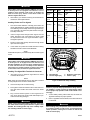
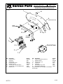
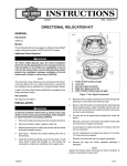
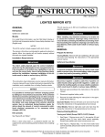
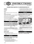
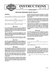
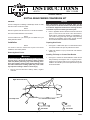
INSTRUCTIONS
-J01731
®
REV. 11-29-99
Kit Number 59657-00
SOFTAIL REAR FENDER CONVERSION KIT
General
CAUTION
This kit is designed for installing a Bobtail style fender on 2000
and later FLSTC and FLSTF models.
NOTE
Rear turn signal kit, Part. No. 68411-97, must also be installed.
When removing the sissy bar, if equipped, make sure the
sissy bar doesn’t contact the fender or the fender paint will
be scratched. Support the fender before removing the fender hardware to prevent scratching the fender paint.
2.
See Service Parts illustration for kit contents.
NOTE
A Service Manual for your motorcycle is available from your
Harley-Davidson dealer.
Refer to applicable Service Manual and follow instructions
given to remove stock rear fender. Save all hardware,
fender support, and tail lamp assembly for reinstallation on
new fender. Keep grab strap and grab strap attaching
hardware for reinstallation. Save ignition module, electrical
box and all associated hardware for reinstallation.
Installation
Preparing New Fender
NOTE
The fender in this kit is finished with a prime coat. Before
installation, have fender painted.
1.
See Figure 1. Install fender clips on T-studs inside kit fender as shown. Make sure clips are positioned as shown.
2.
Install seat retention nut (13) in fender with seat retention
washer (14).
Removing Stock Fender
Installing Tail Lamp on License Plate Bracket
1WARNING
To avoid accidental start-up of motorcycle, and possible
personal injury, disconnect the battery cables (negative
cable first) before performing any of the following procedures. If the battery should contact ground with the negative cable installed, the resulting sparks may cause a battery explosion resulting in death or serious injury.
1.
1.
See Figure 3 and Service Parts illustration. Rotate the tail
lamp assembly 180 degrees from it’s original position.
Install the circuit board with the circuit board screw (8).
Install the stock tail lamp onto license plate bracket (4) with
the saved hardware.
Remove seat and disconnect battery cables, negative
cable first.
i01951
1
Right directional wires
Tail lamp wires
Left directional wires
2
1
P/N 10183
2
P/N 10184
Figure 1. Fender Wire Routing
1 of 3
1WARNING
Federal Motor Vehicle Safety Standard (FMVSS) 108 requires
all motorcycles to be equipped with reflectors. Loss of
visibility to other motorists could result in an accident and
death or serious injury. Install, or have Dealer install, the
reflectors supplied with this kit.
2.
Affix reflector (7) to reflector bracket (9) and install reflector
bracket onto license plate bracket.
Tail lamp wires
Function
No.
Type
Wire color
Right turn
signal
19
2-pin
multilock
V/BN
BK
1
2
V/BN
BK
1
2
BE
HDI only-O/W
or open on domestic
R/Y
BK
1
2
O/W
BN
BE
R/Y
V
BK
1
2
3
4
5
6
Left turn
signal
18
2-pin
multilock
Tail lamp
93
4-pin
multilock
Installing Fender and Turn Signals
1.
See Service Parts illustration. Carefully place fender and
license plate bracket into position between fender supports
and install large stock Phillips screws through fender support, new fender, and into license plate bracket. Don’t tighten Phillips screws now.
2.
Insert turn signal wires through fender support and new
fender, then lift the front of the fender a few inches. Install
the capscrews that hold turn signal assemblies in place,
and tighten capscrews.
3.
Route turn signal and tail lamp harnesses through fender
clips as shown in Figure 1.
4.
Lower fender into position and install all fender mounting
hardware as shown in Service Parts illustration.
Power
In
[94]
6-pin
multilock
Cavity
3
4
Figure 2. Wire Location At Connector
NOTE
Install reflectors (item 5) on fender directly above fender support
covers.
1WARNING
Federal Motor Vehicle Safety Standard (FMVSS) 108 requires
all motorcycles to be equipped with side reflectors. The
mounted saddlebags will cover the factory installed reflectors
on some vehicles. This loss of visibility to other motorists
could result in an accident and death or serious injury. Install,
or have Dealer install, the reflectors supplied with this kit.
4
1
3
Installing Turn Signal Wire Terminals in Connector
1.
See Figures 2 and 3. Install turn signal wires into socket
connector half as shown.
1.
2
NOTE
Make certain the socket terminal slot (on same side of terminal
as crimp tails) faces the connector release button.
2.
Close secondary locks on socket housing.
3.
Place ignition module and electrical box in their stock locations and fasten module with screws saved from fender
removal.
4.
Plug connector halves together. If wire lengths are too
long, secure excess wire to frame with cable straps to prevent wires from being damaged.
1WARNING
Always connect the positive battery cable first. If the positive cable should contact ground with the negative cable
installed, the resulting sparks may cause a battery explosion resulting in death or serious injury.
-J01731
2
Tail lamp [93]
Left turn signal [18]
3
4
Right turn signal [19]
Power in [94]
Figure 3. Rotated tail lamp assembly
1WARNING
Check for proper tail lamp operation before riding motorcycle. Visibility is a major concern for motorcyclists. Failure
to have proper lamp operation could result in death or serious injury.
5.
Connect battery cables, positive cable first, and check turn
signals and tail lamp for proper operation.
6.
Refer to applicable Service Manual, and follow instructions
to install seat.
1WARNING
After installing seat, pull upward on front of seat to be sure
it is locked in position. If seat is loose, it could shift during
vehicle operation, causing loss of control of vehicle and
death or serious injury.
2 of 3
®
Service Parts
sp59657a
Part No. 59657-00
Date 11/99
Softail Rear Fender Conversion Kit
1
14
6,
(underneath fender)
5
stock
hardware
10
13
11
12
stock
hardware
3
2
4
Stock tail lamp
9
7
Item
1
2
3
4
5
6a
6b
7
Description
Fender, primed
Screws (2)
Washers (2)
License plate bracket
Reflectors, red (2)
*Fender clips, T-stud Not shown
*Fender clips, T-stud, small Not shown
Reflector, red
-J01731
Part No.
59914-00
3929
6702
59993-00
59255-91
10183
10184
59988-72
Item Description
8
Screw, circuit board (not shown)
9
Reflector bracket
10
Washers, 3/8 in. (2)
11
Locknuts (4)
12
Screws (2)
13
Seat retention nut, 1/4-20
14
Seat retention washers (2)
*Item 6 includes 6a - 6b. See Figure 1 for illustration
of fender clips.
Part No.
2607
60019-93
6379W
7601
4188
7488
7489A
3 of 3