1
SERVICE MANUAL
AA-07-02.1
January - 2013
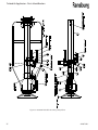
TURBODISK ™ APPLICATOR
ASSEMBLY
MODEL: a11376
IMPORTANT: Before using this equipment, carefully
read SAFETY PRECAUTIONS, starting on page 1, and all
instructions in this manual. Keep this Service Manual
for future reference.
Service Manual Price: $50.00 (U.S.)
Turbodisk Applicator - Contents
CONTENTS
SAFETY:
PAGE
1-4
SAFETY PRECAUTIONS...........................................................................................................
HAZARDS / SAFEGUARDS.......................................................................................................
1
2-4
INTRODUCTION:
5-8
FEATURES.................................................................................................................................
GENERAL DESCRIPTION.........................................................................................................
SPECIFICATIONS......................................................................................................................
TYPICAL SPEED CHART..........................................................................................................
5
5-6
6
7-8
INSTALLATION:
9-10
EQUIPMENT...............................................................................................................................
AIR CONTROL...........................................................................................................................
MOUNTING.................................................................................................................................
INTERLOCKS.............................................................................................................................
TYPICAL LAYOUT OF SYSTEM...............................................................................................
9
9
9
9
10
OPERATION:
11-15
AIR HEATER REQUIREMENTS...............................................................................................
COATING MATERIALS..............................................................................................................
FLUID FLOW CONTROL...........................................................................................................
FLUID VALVE CONTROL..........................................................................................................
TURBODISK FLUID AND AIR PRESSURE REQUIREMENTS..............................................
TURBINE SPEED.......................................................................................................................
TYPICAL MAXIMUM SAFE OPERATING SPEEDS.................................................................
ELECTROSTATIC VOLTAGE...................................................................................................
TARGET DISTANCE..................................................................................................................
11-12
12
12
13
13
14
15
15
15
MAINTENANCE:
17-28
GENERAL....................................................................................................................................
CLEANING PROCEDURES.......................................................................................................
VIBRATION NOISE.....................................................................................................................
TURBINE REPAIR AND REBUILD............................................................................................
VALVES AND REGULATORS...................................................................................................
PREVENTIVE MAINTENANCE..................................................................................................
DISASSEMBLY PROCEDURES................................................................................................
TROUBLESHOOTING GUIDE...................................................................................................
TYPICAL NO VALVE APPLICATION SCHEMATIC .................................................................
TYPICAL 3-WAY VALVE APPLICATION SCHEMATIC............................................................
17
17-19
19
20
20
20-21
21-22
23
24
25
(Continued On Next Page)
Turbodisk Assembly - Contents
Contents (Cont.)
MAINTENANCE (Cont.):
TYPICAL TRIGGER AND DUMP VALVE APPLICATION
W/DR-1 REGULATOR SCHEMATIC..........................................................................................
TYPICAL VALVE ONLY APPLICATION W/DR-1
REGULATOR SCHEMATIC........................................................................................................
TYPICAL TRIGGER AND DUMP VALVE APPLICATION
W/2 DR-1 FLUID REGULATORS SCHEMATIC.........................................................................
PARTS IDENTIFICATION:
A11376 TURBODISK ASSEMBLY MODEL
IDENTIFICATION / PARTS LIST................................................................................................
70988 BASIC SYSTEMS KIT.......................................................................................................
70990-05 TURBODISK ASSEMBLY, NO VALVES /
PARTS LIST.................................................................................................................................
70990-06 TURBODISK ASSEMBLY, 3-WAY VALVES /
PARTS LIST.................................................................................................................................
70990-07 TURBODISK ASSEMBLY, TRIGGER VALVE
ONLY / PARTS LIST....................................................................................................................
70990-08 TURBODISK ASSEMBLY, TRIGGER AND
DUMP VALVE / PARTS LIST......................................................................................................
70990-09 TURBODISK ASSEMBLY TRIGGER VALVE
ONLY W/DR-1 REGULATOR / PARTS LIST.............................................................................
70990-10 TURBODISK ASSEMBLY, TRIGGER AND DUMP
VALVE W/DR-1 REGULATOR / PARTS LIST...........................................................................
70990-11 TURBODISK ASSEMBLY, DUAL DR-1
REGULATORS /PARTS LIST.....................................................................................................
78170-00 DRIVE AIR REGULATOR ASSEMBLY / PARTS LIST..............................................
78166-00 COMPRESSED AIR HOSE ASSEMBLY / PARTS LIST...........................................
78781-00 AIR HEATER AND REGULATOR ASSEMBLY / PARTS LIST.................................
70158-00 FAIRING ASSEMBLY / PARTS LIST..........................................................................
78175-XX TURBODISK AIR TURBINE ASSEMBLY / PARTS LIST.........................................
70879-XXX TURBODISK TURBINE CARTRIDGE ASSEMBLY /
PARTS LIST.................................................................................................................................
TURBODISK APPLICATOR RECOMMENDED SPARE PARTS.............................................
TOOLS AND ACCESSORIES....................................................................................................
PAGE
17-28
26
27
28
29-70
29-31
32-33
35-36
37-38
39-41
43-45
47-49
51-53
55-57
59
60
61-62
63-64
65-66
67-68
69
70
WARRANTY POLICIES:
71
LIMITED WARRANTY..................................................................................................................
71
Turbodisk Applicator - Safety
SAFETY
SAFETY PRECAUTIONS
Before operating, maintaining or servicing any
Ransburg electrostatic coating system, read and
understand all of the technical and safety literature
for your Ransburg products. This manual contains
information that is important for you to know and
understand. This information relates to USER SAFETY
and PREVENTING EQUIPMENT PROBLEMS. To help
you recognize this information, we use the following
symbols. Please pay particular attention to these
sections.
A WARNING! states information to alert you to a
situation that might cause serious injury if instructions
are not followed.
A CAUTION! states information that tells how to
prevent damage to equipment or how to avoid a
situation that might cause minor injury.
A NOTE is information relevant to the procedure in
progress.
While this manual lists standard specifications and
service procedures, some minor deviations may be
found between this literature and your equipment.
Differences in local codes and plant requirements,
material delivery requirements, etc., make such
variations inevitable. Compare this manual with
your system installation drawings and appropriate
Ransburg equipment manuals to reconcile such
differences.
!
WARNING
> The user MUST read and be familiar with the
Safety Section in this manual and the Ransburg safety literature therein identified.
> This manual MUST be read and thor-
oughly understood by ALL personnel who
operate, clean or maintain this equipment!
Special care should be taken to ensure that
the WARNINGS and safety requirements for
operating and servicing the equipment are
followed. The user should be aware of and adhere to ALL local building and fire codes and
ordinances as well as NFPA- 33 SAFETY STANDARD, prior to installing, operating, and/or
servicing this equipment.
!
WARNING
> The hazards shown on the following
page may occur during the normal use of
this equipment. Please read the hazard
chart beginning on page 2.
Careful study and continued use of this manual will
provide a better understanding of the equipment and
process, resulting in more efficient operation, longer
trouble-free service and faster, easier troubleshooting.
If you do not have the manuals and safety literature
for your Ransburg system, contact your local Ransburg
representative or Ransburg.
1
AA-07-02.1
Turbodisk Applicator - Safety
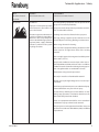
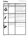
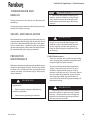
AREA
HAZARD
SAFEGUARDS
Tells where hazards
Tells what the hazard is.
Tells how to avoid the hazard.
Fire Hazard
Fire extinguishing equipment must be present in the
spray area and tested periodically.
may occur.
Spray Area
Improper or inadequate operation
and maintenance procedures will Spray areas must be kept clean to prevent the accumulacause a fire hazard.
tion of combustible residues.
Protection against inadvertent arcing that is capable of causing fire or
explosion is lost if any safety interlocks are disabled during operation.
Frequent power supply shutdown
indicates a problem in the system
requiring correction.
Smoking must never be allowed in the spray area.
The high voltage supplied to the atomizer must be
turned off prior to cleaning, flushing or maintenance.
When using solvents for cleaning:
Those used for equipment flushing should have flash
points equal to or higher than those of the coating
material.
Those used for general cleaning must have flash points
above 100oF (37.8oC).
Spray booth ventilation must be kept at the rates required by NFPA-33, OSHA, and local codes. In addition,
ventilation must be maintained during cleaning operations using flammable or combustible solvents.
Electrostatic arcing must be prevented.
Test only in areas free of combustible material.
Testing may require high voltage to be on, but only as
instructed.
Non-factory replacement parts or unauthorized equipment modifications may cause fire or injury.
If used, the key switch bypass is intended for use only
during setup operations. Production should never be
done with safety interlocks disabled.
Never use equipment intended for use in waterborne
installations to spray solvent based materials.
The paint process and equipment should be set up and
operated in accordance with NFPA-33, NEC, and OSHA
requirements.
AA-07-02.1
2
Turbodisk Applicator - Safety
AREA
HAZARD
SAFEGUARDS
Tells where hazards
Tells what the hazard is.
Tells how to avoid the hazard.
may occur.
General Use and
Maintenance
Improper operation or maintenance Personnel must be given training in accordance with
may create a hazard.
the requirements of NFPA-33.
Personnel must be properly trained Instructions and safety precautions must be read and
in the use of this equipment.
understood prior to using this equipment.
Comply with appropriate local, state, and national codes
governing ventilation, fire protection, operation maintenance, and housekeeping. Reference OSHA, NFPA-33,
and your insurance company requirements.
Electrical
Equipment
High voltage equipment is utilized.
Arcing in areas of flammable or
combustible materials may occur.
Personnel are exposed to high
voltage during operation and
maintenance.
The power supply, optional remote control cabinet,
and all other electrical equipment must be located
outside Class I or II, Division 1 and 2 hazardous areas.
Refer to NFPA-33.
Turn the power supply OFF before working on the
equipment.
Protection against inadvertent arcing that may cause a fire or explosion Test only in areas free of flammable or combustible
is lost if safety circuits are disabled material.
during operation.
Testing may require high voltage to be on, but only as
Frequent power supply shutdown instructed.
indicates a problem in the system
which requires correction.
Production should never be done with the safety circuits disabled.
An electrical arc can ignite coating
materials and cause a fire or explo- Before turning the high voltage on, make sure no objects
sion.
are within the sparking distance.
Halogenated hydrocarbon solvents Aluminum is widely used in other spray application
Explosion Hazard /
Incompatible Materi- for example: methylene chloride equipment - such as material pumps, regulators, trigand 1,1,1,-Trichloroethane are not gering valves, etc. Halogenated hydrocarbon solvents
als
chemically compatible with the
aluminum that might be used in
many system components. The
chemical reaction caused by these
solvents reacting with aluminum
can become violent and lead to an
equipment explosion.
3
must never be used with aluminum equipment during
spraying, flushing, or cleaning. Read the label or data
sheet for the material you intend to spray. If in doubt as
to whether or not a coating or cleaning material is compatible, contact your material supplier. Any other type
of solvent may be used with aluminum equipment.
AA-07-02.1
Turbodisk Applicator - Safety
AREA
HAZARD
Tells where hazards may Tells what the hazard is.
SAFEGUARDS
Tells how to avoid the hazard.
occur.
Toxic Substances
Certain material may be harmful if Follow the requirements of the Material Safety Data
inhaled, or if there is contact with Sheet supplied by coating material manufacturer.
the skin.
Adequate exhaust must be provided to keep the air
free of accumulations of toxic materials.
Use a mask or respirator whenever there is a chance of
inhaling sprayed materials. The mask must be compatible with the material being sprayed and its concentration. Equipment must be as prescribed by an industrial
hygienist or safety expert, and be NIOSH approved.
Spray Area /
High Voltage
Equipment
There is a high voltage device that Parts being sprayed must be supported on conveyors
can induce an electrical charge on or hangers and be grounded. The resistance between
objects which is capable of igniting the part and ground must not exceed 1 megohm.
coating materials.
All electrically conductive objects in the spray area, with
Inadequate grounding will cause the exception of those objects required by the process
a spark hazard. A spark can ignite to be at high voltage, must be grounded.
many coating materials and cause
a fire or explosion.
Any person working in the spray area must be
grounded.
Unless specifically approved for use in hazardous locations, the power supply and other electrical control
equipment must not be used in Class 1, Division 1 or
2 locations.
Personnel Safety/
Mechanical
Hazards
AA-07-02.1
The disk atomizer can rotate at
speeds up to 40,000 RPM. At these
speeds, the edge of the applicator can easily cut into skin. Loose
articles can also be caught by the
rotating disk.
Personnel must stay clear of the disk whenever it is
rotating.
Before touching the disk, the turbine air must be shut
off.
If the disk has been rotating, allow at least three minutes
for it to come to a complete stop before touching it.
4
Turbodisk Applicator - Introduction
INTRODUCTION
FEATURES
GENERAL DESCRIPTION
Features which make the TurbodiskTM Applicator
advantageous for use in electrostatic applications
include:
The Turbodisk Applicator, because of it's high rotational speed, produces finer atomization, improved
quality, and higher transfer efficiency with any of the
wide variety of coating materials (such as waterborne
and high solids) used in production finishing operations. Its speed is controlled by varying the drive
air. The applicator assembly is designed for use on
vertical overhead mounted reciprocators.
• Proven turbine motor reliability.
• Aerodynamic fairing design for ease of cleaning of external surfaces.
• Speed readout (or control) uses reliable magnetic pickup for fiber optic transmission of rotational speed data (optional).
•
A majority of all assembly components which come in contact with the fluid material are made of stainless steel, which is impervious to most fluids.
• Negligible maintenance down time.
•
The easily removable lower fairing, turbine air motor assembly, and the externally mounted regulators and fluid valves, make off line maintenance more efficient and economical.
Conical Disk Assembly
The Turbodisk Applicator uses conical disk assemblies
that are made from high grade aluminum construction and are force balanced to .10 grams•in or better.
With the serrated edge, these disks come in sizes of
6, 9, and 12 inch diameters.
Turbodisk Fairing
(Refer to Figure 17)
The Turbodisk Applicator fairing is required for safe
operation. The two piece fairing provides high voltage isolation from the metal rotator assembly and
valve components, as well as ease of cleaning and
maintenance.
• Higher fluid delivery rates can be achieved using a dual feed fluid system.
• High flow regulators and fluid valves provide for simultaneous paint push out while solvent washes the feed tube and disk.
!
WARNING
> Both sections of the fairing to be in place
when the Turbodisk is in operation or when high
voltage is supplied to the applicator.
5
AA-07-02.1
Turbodisk Applicator - Introduction
Paint Valve Options
Several valve options are available for both single
and dual feed.
SPECIFICATIONS
Mechanical
Turbine Speed:
Variable to 40,000 rpm
max. (6-inch conical disk)
• No Valves
• 3-Way Valves
• Trigger and Dump Valves with DR-1 Regulator
Turbine Type:
Ball Bearing
Weight:
57-lbs. (approximately)
Length: 36-inches
•
•
•
Trigger Valve Only
Diameter:
13.25-inches
Trigger and Dump Valves with Dual DR-1
Regulators
Turbine Air:
At max. speed (40k rpm), requires 103.1 psi and
61.1 SCFM, unloaded
(See "Typical Speed Chart"
in this section.)
Air Temp °F:
120°F maximum at
applicator
Options are:
Trigger Valves with DR-1 Regulator
Power Supply and Controls
In the system, the high voltage is supplied to the
Turbodisk by either the MicroPak™ Industrial power
supply system or a Voltage Master™ series power
supply.
The MicroPak Industrial power supply uses proven
high voltage generator technology that is microprocessor controlled for diagnostics and communication. The controller is packaged in standard rack
mounted Eurocard format for easy access and system
integration.
The Voltage Master™ power supplies are general
purpose heavy duty power supplies with years of
proven reliability. They have variable voltage control,
many safety features, and remote analog voltage
control capabilities.
Fluid Pressure
Inlet: (See "Fluid and Air Pressure Regulator"
in the "Operation" section.)
Single Fluid Flow Range:
Waterborne:
To 1,200 cc/min. maximum
Solvent Base:
To 1,500 cc/min. maximum
High Solids:
To 1,000 cc/min. (80%+) maximum
Air Inlet
Trigger / Dump: Air Pilot for Fluid
Pressure:
(See "Fluid and Air Pressure Regu
lator" in the "Operation" section.)
Electrical
Power Supply AA-07-02.1
70-100 psi
Type:
MicroPak Industrial or Voltage MasterTM
Charging Method:
Direct
Input Voltage:
0-100 kV
Turbine Speed
Control or Monitor:
PulseTrack 2(Optional)
6
Turbodisk Applicator - Introduction
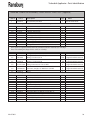
TYPICAL SPEED CHART (RPM's)
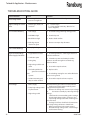
NOTES
(No Load)
(Refer to "Typical Speed Chart")
The following represents data collected under lab
conditions. Flow meters were installed on each of
the two 3/8-inch ID heated air lines used to supply
the Turbodisk turbine motor. The airflow through
each flow meter was recorded and added together
to obtain the total air flow through the system. The
speed of the disk was monitored through the means
of a PulseTrack system. The air heater was set at 120
degrees during all data collection.
Rotational speeds are unloaded and can be expected
to drop 20 to 30% when under a fluid load condition.
Heated turbine air increases efficiency of motor up
to 10%. This chart should be used as a guide ONLY.
Speeds will vary due to rotator wear, tubing size or
lengths, etc.
NOTE
> Never run disk over it's maximum safe
operating speed.
NOTE
> Air heater removes condensation from
OD of motor at high speeds.
7
AA-07-02.1
Turbodisk Applicator - Introduction
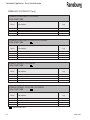
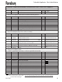
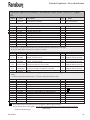
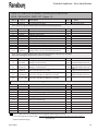
TYPICAL SPEED CHART - 10 HOLE ORIFICE PLATE (NO LOAD)
6" Conical Disk
Disk Speed
(RPM)
Supply Air Pressure
(PSI)
Air Flow #1
(SLPM)
Air Flow #2
(SLPM)
Total Air Flow
(SLPM)
Total Air Flow
(SCFM)
5,000
6.6
140
100
240
8.5
10,000
10.5
190
140
330
11.7
15,000
18.2
260
200
460
16.2
20,000
27.8
340
260
600
21.2
25,000
40.4
440
350
790
27.9
30,000
56.3
560
460
1,020
36.0
35,000
76.4
730
610
1,340
47.3
40,000
103.1
930
800
1,730
61.1
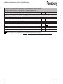
Disk Speed
(RPM)
Supply Air Pressure
(PSI)
Air Flow #1
(SLPM)
Air Flow #2
(SLPM)
Total Air Flow
(SLPM)
Total Air Flow
(SCFM)
5,000
11.3
200
140
340
12.0
10,000
26
330
250
580
20.5
13,000
39.5
430
340
770
27.2
16,000
55.4
560
460
1,020
36.0
19,000
79.8
760
640
1,400
49.4
22,000
102
930
800
1,730
61.1
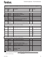
Disk Speed
(RPM)
Supply Air Pressure
(PSI)
Air Flow #1
(SLPM)
Air Flow #2
(SLPM)
Total Air Flow
(SLPM)
Total Air Flow
(SCFM)
2,000
8.7
170
120
290
10.2
4,000
18.6
270
200
470
16.6
6,000
31.0
370
290
660
23.3
8,000
48.3
500
400
900
31.8
10,000
68.5
670
560
1,230
43.4
12,000
95.8
880
750
1,630
57.6
12,500
102.0
930
780
1,710
60.4
9" Conical Disk
12" Conical Disk
AA-07-02.1
8
Turbodisk Applicator - Installation
INSTALLATION
EQUIPMENT
This system should be installed by, or under the
supervision of an Ransburg representative. Should the
need arise to replace any component assembly within
the system, contact your Ransburg representative.
This manual concerns normal operation, maintenance,
and service of the specified applicator assemblies. The
air and fluid connections vary with different models
and installations. This manual deals primarily with
those at, or within the assembly.
AIR CONTROL
(Refer to Figure 1)
Air control of the applicator is from a standard Ransburg air logic panel, which includes two filters (one 40
micron filter located at the air logic station and one
5 micron filter located at the inlet of the in-line air
heater panel). Clean, dry factory air must be provided
to the inlet filter of the air logic station via a minimum
1/4-inch ID pipe and to the inlet filter of the heater
panel via a minimum 3/4-inch ID pipe.
MOUNTING
(Refer to Figure 16)
The Turbodisk assembly is mounted on the reciprocator using four (4) 5/16-18 screws provided on the
ram flange. Loosening two (2) 1/4-20 screws on the
same ram flange will allow the assembly to rotate.
Position the Turbodisk assembly so that the strain
relief boot is positioned toward the incoming fluid
and air lines and retighten.
Remove lower fairing. Thread all the required air, high
voltage, fiber optic, and fluid service lines through the
strain relief boot. The strain relief boot may have to
be cut larger in order to feed all the lines through.
Reinstall lower fairing. Install conical disk and torque
to 50-70 lbs•in (5.65-7.91 Nm).
INTERLOCKS
Flow of coating material should be locked out unless
all of the following conditions are met:
1. Booth exhaust is turned on.
2. The turbine is spinning.
!
WARNING
> The Air Heater Assembly must be located
3. High voltage is on or in the bypass mode.
outside of any hazardous areas as defined by
the NFPA-33,
9
AA-07-02.1
Turbodisk Applicator - Installation
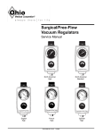
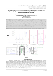
Figure 1: Typical Layout of System
AA-07-02.1
10
Turbodisk Applicator - Operation
OPERATION
!
CAUTION
> Fluids and lubricants used in this system
must contain NO silicones!
> Do NOT operate the unit without an
atomizer disk! Without a disk, overspeed,
resulting in premature bearing failure, is
possible.
> The air supplied to the motor must be
dry, clean, and free of oil or moisture. The
atmospheric dew point should be 10oF or
less. The air heater used should be adjusted
only high enough to prevent condensation
from forming on the motor housing or at the
exhaust port.
!
WARNING
> Operators must be fully trained in safe
operation of electrostatic equipment. Operators must read all instructions and safety
precautions prior to using this equipment
(see NFPA-33).
As with any spray finishing system, operation of
the Turbodisk involves properly setting the operating parameters to obtain the best finish quality for the coating material being sprayed, while
maintaining correct operation and reliability of
the equipment used. Adjustments to operating
parameters, which cover spraying, cleaning, and
on/off control, include:
• Fluid Type
• Fluid Flow Rate
• Turbine Speed
• Electrostatic Voltage
• Target Distance
!
WARNING
> DO NOT exceed the maximum flow rate
of 1500 cc/min. during painting or purge
cycles. Excessive fluid flow may cause an
imbalance condition and possibly premature
bearing failure.
AIR HEATER REQUIREMENTS
Turbine drive air expands as it moves through the
turbine wheel cavity and as it exits the turbine from
the exhaust port. This expansion will cause cooling
of the exhaust air and the surfaces it contacts. This
cooling effect can cause surface temperatures to fall
below the dew point of the booth, which will result
in condensation on the interior and exterior of the
atomizer, machine, and its components. It is even
possible that the temperature of the supply air may be
below the booth dew point, even without additional
expansion cooling.
Condensation is especially probable in waterborne
applications when booth temperature and relative
humidity levels are typically maintained very high.
This condensation will allow sufficient conductivity of the surfaces such that they act as an erratic
ground source potential. This can cause damage to
the equipment.
It is therefore, a requirement that turbine exhaust air
temperature be maintained about the booth dew
point to prevent condensation from forming on
atomizer surfaces. Doing so will eliminate moisture
as a potential defect in painted surfaces as well as
extending equipment life. Thus, it is recommended
that air heaters be installed into the atomizer air supply
lines, i.e. turbine drive air. The air heaters must be of
sufficient capacity, capable of raising the incoming
air temperature at least 40°F (4.4°C) at a flow rate of
60 SCFM per applicator.
The actual air heater process setting depends on the
applicator fluid flow rate load, booth conditions, turbine airflow settings, and incoming air temperature.
11
AA-07-02.1
Turbodisk Applicator - Operation
The heater should be set as low as possible, sufficient
to maintain the applicator surface temperatures
above the dew point in the booth.
FLUID FLOW CONTROL
Example: Only with the incoming air temperature at
72°F (22.2°C), a disk rotating unloaded at 30 krpm has
a turbine outlet temperature drop of approximately
28°F (-2.2°C) (@ 40 krpm unloaded, DT ~ 14°F (-.10°C)
). Referring to the ASHRAE Psychrometric chart, the
saturation temperature range (dew point) of a spray
booth maintained at 70-75°F / 65-70% RH is 62-68°F
(21.1-23.9°C / 76-70° RH is 16.7-20°C). Thus, it is
almost certain that the surface temperatures of the
applicator will fall below the dew point of the booth,
and an air heater will be needed in this case.
Fluid flow control is dependent on the valve configuration of the Turbodisk . If the Turbodisk is configured with no valves or a 3-way valve, fluid flow
is controlled externally at the paint source. If the
Turbodisk is equipped with a regulator, fluid flow
can be controlled via the air pilot signal. The high
flow and low flow regulators each have procedures
on how to control and deliver consistent fluid flows.
For more information on controlling the fluid delivery
using regulators, refer to that specific manual which
is included with the system.
To prevent condensation, an air heater assembly
should be assembled after air filters. (Reference the
current “Air Heater Assembly” service manual for
further information.)
To check fluid flow rates, the disk must be removed.
See the "Maintenance" section for "Removal Procedure". The fluid can then be manually triggered to
measure actual flow in a graduated beaker over a
specified time period.
(Refer to Figures 14 and 15)
!
WARNING
> Danger of shock and/or personal injury
NOTE
> Failure to use an air heater may cause
damage to equipment or ruin the finished
component being processed.
can occur. Proper grounding procedures,
which are outlined in the ITW Ransburg safety
bulletins, must be followed. Personnel must
never work near or perform work on the
turbine when the turbine is spinning or when
high voltage is on.
COATING MATERIALS
The Turbodisk can be used with a broad range of
coating material conductivities. However, with waterborne paints, it may be necessary to isolate the
paint supply from ground.
!
WARNING
> Isolated fluid supplies using either
waterborne or highly conductive solvent
base coatings can produce hazardous high
voltage discharges which can cause fires or
injury to personnel.
AA-07-02.1
12
Turbodisk Applicator - Operation
FLUID VALVE CONTROL
Trigger and Dump
(Refer to "Turbodisk Fluid and Air Pressure Requirements")
The fluid valves in the Turbodisk are actuated by an air
signal. The air pressure must exceed 70 psi to assure
proper actuation of the valve. Applying air to the valve
actuator turns on the fluid flow for that valve.
The trigger valve controls the paint flow to the disk.
When actuated, paint flows through the valve to
the fluid tube. The disk should be spinning at a rpm
speed that is fast enough, (that when fluid is turned
on) to enable the fluid to flow through the disk paint
passage holes and be atomized.
The dump valve controls the paint flow through the
dump line. When actuated, paint flow is directed to the
dump return line. This provides a method of rapidly
removing paint from the incoming line for cleaning
and/or color change. Normally, the dump valve is not
actuated at the same time as the paint trigger valve
since the trigger valve is intended to cause the fluid
flow to the disk at the prescribed input pressure.
FLUID AND AIR PRESSURE REQUIREMENTS
(Refer to "Turbodisk Fluid and Air Pressure Requirements")
Fluid and air pressure requirements are dependent
on the fluid trigger valve configuration.
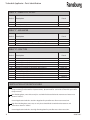
TURBODISK FLUID AND AIR PRESSURE REQUIREMENTS
Air Pilot Fluid
Regulator
Air Inlet Trigger/
Dump Valve
Fluid Inlet Pressure
Solvent Inlet
No
Valves
3-Way ON/OFF
(18283)
Trigger/Dump
W/High Flow
(70171-04)
Regulator
Trigger/Dump
W/Low Flow
DR-1 (74151) Regulator
------------------
------------------
100 psi max.
100 psi
------------------
120 psi max.
70-100 psi
70-100 psi
------------------
300 psi max.
80-100 psi max.
80-100 psi max.
------------------
30-60 psi max.
30-60 psi max.
30-60 psi max.
Note: Trigger/dump valves (CCV-403-SS) are rated to 300 psi maximum inlet fluid pressure but are limited
to the lower pressure limit of the fluid regulators.
13
AA-07-02.1
Turbodisk Applicator - Operation
TURBINE SPEED
Turbine speed is determined by the drive air pressure
at the rotary atomizer and fluid flow rate.
Turbine speed can be closed loop controlled using
the fiber optic speed transmitter mounted at the back
of the turbine rotator assembly as a speed input to
remote speed controls such as the PulseTrack 2.
Atomizers
(Refer to "Typical Maximum Safe
Operating Speeds")
!
WARNING
> Never operate any disk atomizer in
excess of it's maximum rated speed ("K"
number) as listed in the service manual. Excessive speed may cause the disk to disintegrate, causing serious damage and/or injury.
NOTE
> The disk rotational speed determines
the quality of atomization and can be varied
for different flow rates and viscosities. For
optimum transfer efficiency and spray pattern control, the disk rotational speed should
be set at the minimum required speed to
achieve proper atomization.
Excessive speed reduces transfer efficiency!
All atomizers manufactured after April 6, 1982, bear a
“K”number. That number indicates the maximum safe
rotation speed for that series in tens of thousands.
For example:
9K = 9,000 rpm maximum safe speed, 40K = 40,000 rpm, etc.
If you have an atomizer that does not have a “K”
number, contact your ITW Ransburg repre-sentative
for its maximum safe operating speed.
!
WARNING
> Do not exceed the maximum rated
speed of 40,000 rpm for the 6 inch conical
disk and 27,000 rpm for the 6 inch uni-disk.
This maximum speed includes speed overshoot when fluid delivery is stopped. Damage to persons or equipment may result in
over-speed conditions.
AA-07-02.1
!
WARNING
> Inspect disk platter daily for wear or
damage. Replace if excessively worn or
damaged. Worn or damaged disk platters
can cause an imbalanced condition and
shorten bearing life. Warranty will be voided
if damaged disks are used.
14
Turbodisk Applicator - Operation
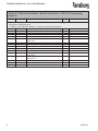
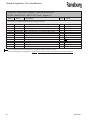
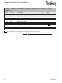
TYPICAL MAXIMUM SAFE OPERATING SPEEDS
Disk Type
Part Number
Max. RPM
None
Conical Disk Assy., Serrated, 6", Aluminum, Not Anodized
Conical Disk Assy., Serrated, 6" Aluminum, Anodized
Conical Disk Assy., Serrated, 9", Aluminum, Not Anodized
Conical Disk Assy., Serrated, 9", Aluminum, Anodized
Conical Disk Assy., Serrated, 12", Aluminum, Not Anodized
Conical Disk Assy., Serrated, 12", Aluminum, Anodized
Uni-Disk Assy., 6", Aluminum, Not Anodized
Uni-Disk Assy., 8", Aluminum, Not Anodized
Uni-Disk Assy., 10", Aluminum, Not Anodized
Uni-Disk Assy., 12", Aluminum, Not Anodized
-20485-62
20485-65
20485-92
20485-95
20485-122
20485-125
19830-06
19830-08
19830-10
19830-12
-40,000
40,000
25,000
25,000
15,000
15,000
27,000
23,000
15,000
15,000
ELECTROSTATIC VOLTAGE
TARGET DISTANCE
In the system, the high voltage is supplied to the Turbodisk by either the MicroPak Industrial power supply
system or Voltage Master series power supplies.
The distance between the Turbodisk and the target
will affect the finish quality, penetration, and efficiency. Closer distances give wetter finishes and
greater efficiency, while greater distances give drier
finishes. The recommended normal disk edge to
target range is 12-inches (305mm) minimum for
optimum performance.
The MicroPak industrial power supply uses proven
high voltage generator technology that is microprocessor controlled for diagnostics and communication. The controller is packaged in standard rack
mounted Eurocard format for easy access and system
integration.
The Voltage Master power supplies are general purpose heavy duty power supplies with years of proven
reliability. They have variable voltage control, many
safety features, and remote analog voltage control
capabilities.
15
AA-07-02.1
Turbodisk Applicator - Operation
NOTES
AA-07-02.1
16
Turbodisk Applicator - Maintenance
MAINTENANCE
GENERAL
!
Verify daily that the operating parameters have not
varied dramatically. A sudden change or even a
gradual decay in performance could be early indications of component failure.
Normal maintenance procedures should be established and recorded at the initial start-up. All maintenance schedules are subject to variation based on
use. Periodically review these maintenance schedules
as equipment ages and needs change.
CLEANING PROCEDURES
!
WARNING
> Electrical shock and fire hazards can exist during maintenance. The power supply
must be turned off before entering the spray
area. Spray booth fans should remain on
while cleaning with solvents.
> Never touch the disk atomizer while it
is spinning. The edge of the disk can easily
cut into human skin, gloves or other materials. Be sure the disk atomizer has completely
stopped spinning before attempting to
touch it. Approximate time for the disk to
stop spinning after turning off the drive air is
about three minutes.
WARNING
> Because of the hazard of bearing pen-
etration, solvents should be used sparingly!
They should NEVER be hosed directly onto
the atomizer, motor housing, or any fiber
optic juncture.
!
WARNING
> NEVER wrap the applicator in plastic to
keep it clean. A surface charge may build up
on the plastic surface and discharge to the
nearest grounded object. Efficiency of the
applicator will also be reduced and damage
or failure of the applicator components may
occur. WRAPPING THE APPLICATOR IN PLASTIC WILL VOID WARRANTY.
!
CAUTION
> Do not immerse the Turbodisk assembly
in solvent or other liquids. Turbine components will be damaged.
> Do not soak the disk in solvent longer
than 24 hours.
!
WARNING
> Inspect disk platter daily for wear or
In addition to the above Warning, which relates to
potential safety hazards, the following information
must be observed to prevent damage to the equipment.
17
damage. Replace if excessively worn or
damaged. Worn or damaged disk platters
can cause an imbalanced condition and
shorten bearing life. Warranty will be voided
if damaged disks are used.
AA-07-02.1
Turbodisk Applicator - Maintenance
Internal Fluid Path Cleaning
With the high voltage turned off and the disk spinning,
flush cleaning solvent through the incom-ing paint
line or through the solvent inlet line. If it is desired to
clean just the face of the disk off, flush solvent through
the solvent inlet. If a color change is required, flush
the entire system. The spinning disk will atomize the
solvent and clean out the disk passages. If equipped,
trigger the dump valve to catch the wasted paint from
the incoming line, then flush the disk with solvent
after closing the dump valve.
!
WARNING
> Never submerge a disk into a solvent
bath while still mounted on the shaft. Solvent may intrude into bearing cavity and
destroy the grease. Remove disk to hand
clean or run disk and flush through trigger
and dump valves.
NOTE
> Solvent flushing of the system (except
during color change) should be done with
the disk dismounted and with waste solvent
collected in a grounded container.
External Atomizer Surface Cleaning
!
WARNING
> To reduce the risk of fire or explosion,
OSHA and NFPA-33 require that solvents
used for exterior cleaning, including disk
cleaning and soaking, be nonflammable
(flash points higher than 100oF/37.8oC).
Since electrostatic equipment is involved,
these solvents should also be nonpolar. Examples of nonflammable, nonpolar solvents
for cleaning are: Amyl acetate, methyl amyl
acetate, high flash naphtha and mineral
spirits.
> Do not use conductive solvents such as
MEK to clean the external surfaces of the
Turbodisk.
> Never lower the Turbodisk assembly into
a drum for flushing or color changing.
Disk Cleaning
Normally, the internal cleaning instructions will suffice to clean the disk. If flushing the disk does not
remove all the residue, the disk may be removed for
hand cleaning. Unscrew mounting nut and remove
the disk by using the supplied disk puller.
NOTE
> The turbine shaft must be held with a
7/16” open end wrench while using the disk
puller.
!
WARNING
> Do not hold disk edge during removal.
This could result in injury.
AA-07-02.1
18
Turbodisk Applicator- Maintenance
Inspection of the disk is required to determine if
wear to the serrated edge or damage has occurred.
Wear can cause a reduction in transfer efficiency and
excessive paint wrap on the atomizer fairing.
Clean the disk by soaking in an appropriate solvent to
loosen paint residue. Do not soak for more than a 24
hour period. Use a soft cloth to remove the paint from
the surface and a soft bristle brush to remove paint
from the well area. The splash plate may need to be
removed to clean the paint well. The screws must be
retorqued to 24 lbs•in (2.71 Nm) after cleaning.
CAUTION
> Do not use abrasive materials which will
scratch or damage the disk. Cleaning pads
such as Scotch-Brite® should not be used.
> Using an atomizer disk with paint buildup
may cause an imbalance. This may result in
bearing damage and turbine failure. This
condition may also stress the disk when operating at high speeds.
Reinstall the disk and torque the mounting nut to
50-60 lbs•in (5.65-6.78 Nm).
> Before reinstalling the disk onto the shaft,
check and clean the tapered mating surface
for paint residue.
WARNING
> Care must be taken when mounting the
disk assembly to the motor shaft. The mounting nut should turn freely for several turns
until it fully bottoms on the disk assembly.
Tighten to 50-70 lbs•in (5.65-7.91 Nm).
!
> Do not attempt to clean the disk edge
while it is rotating. Do not attempt to slow
down or stop the disk by holding a rag or a
gloved hand against the edge. This could
cause physical harm and/or damage to the
disk.
!
WARNING
> Replace disk platter if damaged. War-
ranty will be voided if damaged dish platter
is used.
!
VIBRATION NOISE
If the Turbodisk is vibrating or making an unusual
loud noise, it may mean that there is an unbalanced
situation or a bearing failure. The disk could have
dried paint or could be damaged. This situation
should be corrected immediately. Do not continue
to operate a noisy turbine.
WARNING
> Inspect disk platter daily for wear or
damage. Replace if excessively worn or
damaged. Worn or damaged disk platters
can cause an imbalanced condition and
shorten bearing life. Warranty will be voided
if damaged disks are used.
19
!
!
WARNING
> If a disk has been mishandled or there
appears to be damage on the face, DO NOT
USE. Serious injury can result from rotating
a defective disk. If there is a concern about
the condition of a disk, please return it to
Ransburg for evaluation.
AA-07-02.1
Turbodisk Applicator - Maintenance
TURBINE REPAIR AND
REBUILD
!
CAUTION
> Because of the hazard of bearing pen-
etration, solvents should be used sparingly.
They should never be hosed directly onto
the atomizer, motor housing or fiber optic
juncture.
Turbine motor must be returned to Ransburg for
rebuilding.
Any attempt to disassemble turbine during warranty
period will void the warranty.
VALVES AND REGULATORS
!
No maintenance is normally required on the valves or
regulator other than flushing with solvent daily. Visual
inspections should be made on the valves and regulator on a weekly basis. Should the valve or regulator
not function properly, refer to the individual manuals
for troubleshooting and repair procedures.
PREVENTIVE
MAINTENANCE
Before any shutdown or maintenance, the fluid system
should be thoroughly flushed. All cleaning should
be done with a minimum of the appropriate clean
solvent and clean, soft, lint free rags or soft brushes
where indicated.
!
WARNING
> Do not stop disk rotation by using a rag or
gloved hand.
> Make sure high voltage is off before approaching applicator.
> Follow proper grounding procedures.
AA-07-02.1
WARNING
> Personnel working on applicators MUST
always be sure that the high voltage is off,
the fluid system is flushed and off, the rotator has stopped, and that the grounding
hook has been properly secured to the motor housing.
Daily Maintenance
• Clean the atomizer disk, motor housing, fairing, and as needed, the peripheral equipment with nonpolar high flash point solvents.
•
To prevent solvent penetration beyond the slinger, a minimal air pressure of 5 to 10 psi should be applied to the motor in order to maintain a positive pressure. The motor should be run at operating speed for several minutes after cleaning to keep any solvent that has accumulated at the seals from penetrating into the motor housing.
!
WARNING
> Positive air pressure must be maintained
to prevent solvent or paint intrusion into the
bearings. Solvent and/or paint will degrade
the grease in the bearings and cause failure.
Warranty will not cover this!
20
Turbodisk Applicator - Maintenance
• Inspect the disk edge and face. If damage exists, DO NOT USE. Return it to Ransburg for evaluation.
• Check the fluid feed tube to make sure it is not rubbing the disk.
Weekly Maintenance
Follow the normal daily maintenance schedule,
then:
• Monitor rotational speed at the control and verify it is within 5% of target speed.
• Monitor high voltage output indicated on the power supply display. Verify with high voltage probe and meter.
•
Remove fairing and clean all internal components: valves, regulators, and tubing. Check tubing for evidence of pin-holes, kinks, and abrasions.
• If the muffler needs to cleaned (item is to be solvent cleaned) remove it from the motor. Clean and dry the muffler before reinstalling it.
•
Check fluid flows by removing the disk and manually triggering the paint valve. Measure the amount of fluid in a graduated beaker over a specific time to determine flow rate.
•
Clean and inspect the disk face. Look for wear, which can cause poor transfer efficiency and excessive paint wrap on the atomizer fairing. Disk removal, cleaning and inspection may be done more or less frequently, depending upon use.
DISASSEMBLY PROCEDURES
Prior to disassembly, verify the following:
• The atomizer disk, valves and regulator have been flushed with solvent and purged dry with air.
• The disk has stopped rotating.
• The air supply to the trigger valves and regulator have been turned off.
• The fluid and solvent supply have been turned off and the pressure has been relieved.
• The high voltage has been turned off and the motor housing grounded.
Turbine Cartridge Exchange
(Refer to Figure18)
Removal
1. Remove disk mounting nut by holding the rotator shaft above the disk with a 7/16-inch open end
wrench and unscrewing the mounting nut with a
3/8-inch Allen wrench.
2. Install the ITW Ransburg 19850-00 disk puller into
disk to remove it.
3. Carefully remove lower fairing.
!
WARNING
> Handle the disk with caution. The sharp
edge can cut even though it is not rotating.
4. Next remove screws holding the fluid tube assembly.
21
AA-07-02.1
Turbodisk Applicator - Maintenance
5. With a 7/64-inch Allen wrench, remove six (6)
socket head cap screws, which secures the turbine
cartridge to the motor housing.
6. Using a 1/16-inch Allen wrench, turn each of the
three (3) jack screws, located next to socket head
cap screw, clockwise not more than one half turn at
a time in sequence to separate the motor from the
housing.
!
CAUTION
4. To avoid losing the jack screws during normal
operation, torque to 2-3 lbs•in (0.23-0.34 Nm).
Turbine Cartridge Service
This cartridge is a precision instrument and should
be handled with care. The bearings are preloaded to
30 lbs. (13-6 Kg) and dynamically balanced.
Turbine bearing unit must be returned to Ransburg
for rebuilding.
> Failure to perform this step correctly
!
may result in misalignment and possible
damage.
> Failure to observe the following cautions
will result in diminished performance and
premature motor failure.
> Use caution in removing cartridge to
prevent it from falling out of the housing.
!
CAUTION
> Any attempt to disassemble turbine during the warranty period will void the warranty.
Installation
Always check the inside of the motor housing and
clean, if required, with a minimum amount of an appropriate cleaning solvent and a soft cloth.
1. Using a 1/16-inch Allen wrench, retract the three
(3) jack screws.
2. With o-rings in place on the nozzle plate and
housing, insert the turbine cartridge into motor
housing.
!
CAUTION
> Lightly lubricate o-rings with petroleum
jelly before assembly. Fit parts with
o-rings very carefully. They must not be allowed to distort, unseat or break.
3. Secure the rotator assembly to the housing with
six socket head cap screws. Tighten the screws in
sequence until the cartridge is fully engaged into
the housing to prevent misalignment and possible
damage. Torque to 10 lbs•in.
AA-07-02.1
CAUTION
NOTES:
• Never use any silicone compound in this system!
• Never use any lubrication on the bearings!
• Never use any solvent on the bearings!
•
Never exert force on one race of a bearing assembly that may be transmitted to the other race through the bearings! Force and resist-
ance must always be on the same race in order to prevent damage.
• Do not enlarge the nozzle passages during cleaning, as it will effect performance.
• Always observe the specified torque in tightening fasteners.
• Clean all parts thoroughly with an appropriate, clean solvent. Inspect them for wear or damage and replace as required.
• Check all flow passages for obstruction, particularly the nozzle plate. Clear as required.
•
Discard o-rings and replace with new. Lightly
lubricate o-rings with petroleum jelly before
assembly. Fit parts with o-rings very carefully.
They must not be allowed to distort, unseat, or
break.
22
Turbodisk Applicator - Maintenance
TROUBLESHOOTING GUIDE
Cause
Solution
Fluctuating Pattern
1. Not enough back pressure on regulator
1. See regulator manual for diagnosis.
Light Coverage on Some
Parts
1. Part hangers, hooks, are
not clean
1. a. Clean hangers.
b. Check ground continuity. (Must be less than 1 Megohm.)
Poor Transfer Efficiency
1. Low voltage
1. Check disk voltage with high voltage probe.
2. Disk RPM to high
2. Slow disk speed.
3. Booth flow to high
3. Reduce booth air flow.
4. Disk edge to part distance to great
4. Decrease conveyor loop diameter.
Low Current Readings
1. Dirty high voltage contacts
1. Clean and/or replace.
High Current Readings /
Power Supply Overloads
1. Target distance to close
1. Check target distance. Ideal target distance is 12-inches minimum.
General Problem
2. Conductive paint
3. Fairing dirty
4. High voltage cable break down
Low Voltage
3. Clean with nonpolar solvent.
5. Fluid tube pinholed to ground on conductive
paint
systems
4. Replace cable.
6. Isolation mounting rod dirty or carbon tracked
6. Clean with nonpolar solvent or replace.
1. Power supply
Use the following procedure to isolate problem:
- Verify power supply output. Refer to power supply manual for procedure.
- Remove the fairing and measure input voltage
to the rotator assembly by removing the high
voltage
cable from the connector fitting and inserting it
into the high voltage probe. If voltage is low,
replace high voltage cable with a known good one and retest.
- If voltage is still low, check for bad connections in the high voltage Junction or Switch Tank.
Refer to procedures in the proper manual.
- Reinstall the high voltage cable. Check voltage
at the rotator housing.
2. Faulty high voltage switch or junction tank
3. High voltage cable
23
2. Solventbase paint conductivity should be between .05 and 20 megohms on Ransburg Paint Test Meter.
5. Check tubing routing for areas where fluid tube comes near a ground.
AA-07-02.1
Turbodisk Applicator - Maintenance
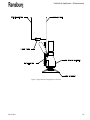
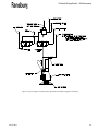
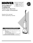
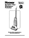
Figure 2: Typical No Valve Application Schematic
AA-07-02.1
24
Turbodisk Applicator - Maintenance
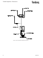
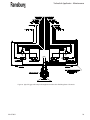
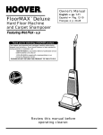
Figure 3: Typical 3-Way Valve Application Schematic
25
AA-07-02.1
Turbodisk Applicator - Maintenance
Figure 4: Typical Trigger and Dump Valve Application with DR-1 Regulator Schematic
AA-07-02.1
26
Turbodisk Applicator - Maintenance
Figure 5: Typical Trigger Valve Only Application with DR-1 Regulator Schematic
27
AA-07-02.1
Turbodisk Applicator - Maintenance
Figure 6: Typical Trigger and Dump Valve Application with 2 DR-1 Fluid Regulators Schematic
AA-07-02.1
28
Turbodisk Applicator - Parts Identification
PARTS IDENTIFICATION
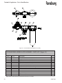
A11376 TURBODISK ASSEMBLY MODEL IDENTIFICATION
Turbodisk Assemblies are available with the various options as follows:
Model No.
A11376 -
x x x x X X
XX
Part G - Disk Type
Part F - Air Heater
Part E - Fiber Optic Pickup
Part D - Paint Hose
Part C - Fluid Control Valve Kit
Part B - Fairing
Part A - Basic Systems Kit With High Speed Air Motor
Basic Part Number
TABLE "A" - BASIC SYSTEMS KIT W/HIGH SPEED AIR MOTOR
Dash #
1
2
3
4
5
6
7
8
29
Description
Kit Part #
Mounting
Nut 9
Downfeed Clockwise - No Tilt
Downfeed Counter-Clockwise - Not Tilt
Upfeed Clockwise - No Tilt
Upfeed Counter-Clockwise - No Tilt
Downfeed Clockwise - No Tilt
Downfeed Counter-Clockwise - No Tilt, Dual Feed Tube
Upfeed Clockwise - Not Tilt, Dual Feed Tube
Upfeed Counter-Clockwise - No Tilt, Dual Feed Tube
70988-01
70988-02
70988-03
70988-04
70988-05
70988-06
70988-07
70988-08
19836-01
19836-02
19836-03
19836-04
19836-05
19836-06
19836-07
19836-08
AA-07-02.1
Turbodisk Applicator - Parts Identification
TABLE "B" - FAIRING
Dash #
0
2
Description
None
Fairing
Part #
-70158-02
TABLE "C" - FLUID CONTROL VALVE KIT
Description
Kit Part #
DR-1 or
High Flow
Reference
5
6
No Valves or Fluid Regulator
3-Way Valve, No Fluid Regulator
70975-05
70975-06
70975-05
70975-06
7
8
Trigger Valve with High Flow Fluid Regulator
Trigger & Dump Valve with High Flow Fluid Regulator
70975-07
70975-08
70171-04
70171-04
A
B
C
D
E
F
G
Trigger Valve with DR-1 Fluid Regulator, 1:2 Ratio
Trigger Valve with DR-1 Fluid Regulator, 1:4 Ratio
Trigger Valve with DR-1 Fluid Regulator, 1:6 Ratio
Trigger Valve with DR-1 Fluid Regulator, 1:8 Ratio
Trigger Valve with DR-1 Fluid Regulator, 1:10 Ratio
Trigger Valve with DR-1 Fluid Regulator, 1:3 Ratio
Trigger Valve with DR-1 Fluid Regulator, 1:1 Ratio
70975-09
70975-09
70975-09
70975-09
70975-09
70975-09
70975-09
74151-01
74151-02
74151-03
74151-04
74151-05
74151-06
74151-11
H
J
K
M
N
P
R
S
Trigger & Dump Valve with DR-1 Fluid Regulator, 1:2 Ratio
Trigger & Dump Valve with DR-1 Fluid Regulator, 1:4 Ratio
Trigger & Dump Valve with DR-1 Fluid Regulator, 1:6 Ratio
Trigger & Dump Valve with DR-1 Fluid Regulator, 1:8 Ratio
Trigger & Dump Valve with DR-1 Fluid Regulator, 1:10 Ratio
Trigger & Dump Valve with DR-1 Fluid Regulator, 1:3 Ratio
Trigger & Dump Valve with DR-1 Fluid Regulator, 1:1 Ratio
Trigger & Dump Valve with (2) DR-1 Fluid Regulator, 1:1 Ratio
70975-10
70975-10
70975-10
70975-10
70975-10
70975-10
70975-10
70975-11
74151-01
74151-02
74151-03
74151-04
74151-05
74151-06
74151-11
74151-11
Dash #
6
6
7
7
7
7
7
7
7
7
7
7
7
7
7
7
7
TABLE "D" - HOSE FOR PAINT SYSTEM
Dash #
0
4
5
6
AA-07-02.1
Description
None
3/8" OD
1/2" OD
1/4" OD
Part #
-70977-04
70977-05
70977-06
30
Turbodisk Applicator - Parts Identification
TABLE "E" - FIBER OPTIC PICKUP
Dash #
0
1
Description
Part #
None
Fiber Optic Pickup
-SMC-29
TABLE "F" - AIR HEATER
Dash #
0
1
2
Description
None
Air Heater Manifold Package With High Flow Regulator
Regulator Assembly - No Heater
Part #
-78781-00
78170-00
TABLE "G" - DISK TYPE
Dash #
00
01
02
03
04
05
06
07
08
09
10
Description
None
Disk Assy., Serrated, 6", Aluminum, Not Anodized
Disk Assy., Serrated, 6", Aluminum, Anodized
Disk Assy., Serrated, 9", Aluminum, Not Anodized
Disk Assy., Serrated, 9", Aluminum, Anodized
Disk Assy., Serrated, 12", Aluminum, Not Anodized
Disk Assy., Serrated, 12", Aluminum, Anodized
Uni-Disk Assy., 6", Aluminum, Not Anodized
Uni-Disk Assy., 8", Aluminum, Not Anodized
Uni-Disk Assy., 10", Aluminum, Not Anodized
Uni-Disk Assy., 12", Aluminum, Not Anodized
Part #
-20485-62
20485-65
20485-92
20485-95
20485-122
20485-125
19830-06
19830-08
19830-10
19830-12
* PARTS LIST BULLET DEFINITION TABLE
9
7
(1) Disk Mounting Nut (See "Table A") is included with this assembly. When mounting disk (not included),
torque mounting nut to 50-60 lbs•in (5.65-6.75 Nm). (Recommended: 3/8" hex bit socket with square drive
torque wrench.)
DR-1 Fluid Regulator, 74151-XX can only be used with Fluid Control Valve Kits 70975-09 and 70975-10 as
shown in "Table C".
General Application Guideline: Use DR-1 Regulator for paint flow rates from 25 to 1500 cc/min.
6
High Flow Fluid Regulator, 70171-04, can only be used with Fluid Control Valve Kits 70975-07 and
70975-08 as shown in "Table C".
General Application Guideline: Use High Flow Regulator for paint flow rates above 750 cc/min.
31
AA-07-02.1
Turbodisk Applicator - Parts Identification
70988 BASIC SYSTEMS KIT
70988-01 DOWNFEED, CLOCKWISE
Part #
78175-02
70973-01
70976-01
19850-00
Qty
Description
1
1
1
1
Air Motor, High Speed
Basic Mounting Parts Kit
Feed Tube Kit
Disk Puller Assembly
70988-02 DOWNFEED, COUNTER-CLOCKWISE
Part #
78175-12
70973-01
70976-01
19850-00
78175-02
70973-01
70976-02
19850-00
78175-12
70973-01
70976-03
19850-00
1
1
1
1
1
Air Motor, High Speed
Basic Mounting Parts Kit
Feed Tube Kit
Disk Puller Assembly
1
Qty
Description
1
1
1
1
Air Motor, High Speed
Basic Mounting Parts Kit
Feed Tube Kit
Disk Puller Assembly
70988-04 UPFEED, COUNTER-CLOCKWISE
Part #
Qty
Description
70988-03 UPFEED, CLOCKWISE
Part #
1
Description
Air Motor, High Speed
Basic Mounting Parts Kit
Feed Tube Kit
Disk Puller Assembly
1
Qty
1
1
1
1
Special Order Only.
AA-07-02.1
32
Turbodisk Applicator - Parts Identification
70988 BASIC SYSTEMS KIT (Cont.)
70988-05 DOWNFEED, CLOCKWISE
DUAL FEED TUBE
Part #
78175-02
70973-01
70976-01
19850-00
Description
Air Motor, High Speed
Basic Mounting Parts Kit
Feed Tube Kit
Disk Puller Assembly
Qty
1
1
2
1
70988-06 DOWNFEED, COUNTER-CLOCKWISE
1
DUAL FEED TUBE
Part #
78175-12
70973-01
70976-01
19850-00
Description
Air Motor, High Speed
Basic Mounting Parts Kit
Feed Tube Kit
Disk Puller Assembly
Qty
1
1
2
1
70988-07 UPFEED, CLOCKWISE
1
DUAL FEED TUBE
Part #
78175-02
70973-01
70976-02
19850-00
Description
Air Motor, High Speed
Basic Mounting Parts Kit
Feed Tube Kit
Disk Puller Assembly
Qty
1
1
2
1
70988-08 UPFEED, COUNTER-CLOCKWISE
1
DUAL FEED TUBE
Part #
78175-12
70973-01
70976-03
19850-00
1
33
Description
Air Motor, High Speed
Basic Mounting Parts Kit
Feed Tube Kit
Disk Puller Assembly
Qty
1
1
2
1
Special Order Only.
AA-07-02.1
Turbodisk Applicator - Parts Identification
NOTES
AA-07-02.1
34
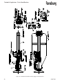
Turbodisk Applicator - Parts Identification
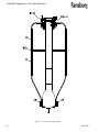
Figure 7: 70990-05 Turbodisk Assembly, No Valves
35
AA-07-02.1
Turbodisk Applicator - Parts Identification
70990-05 TURBODISK ASSEMBLY, NO VALVES - PARTS LIST (Figure 7)
Item #
1
Part #
70976-01
Description
Feed Tube Kit, Downfeed
Notes
Qty
1
Part of 70989-XX Kit
These parts are supplied with Kit 70973-01 Hardware & Mounting Parts Kit
2-1
8156-24F
Screw, 5/16-24 X 3/4", Hex Head
2
2-2
8156-32F
Screw, 5/16-24 X 1", Hex Head
5
2-3
8156-40F
Screw, 5/16-24 X 1-1/4", Heax Head
1
2-4
7734-07
L Washer, Spring, 5/16"
6
2-9
15980-00
Extension Arm, Air Motor
1
2-10
1613-03
Tube Support, 20-3/8"
1
2-11
8156-48F
Screw, 5/16-24 X 1-1/2", Hex Head (Not Used)
2
2-13
27141-081
Hose Wrapping (Not Shown)
25'
Same as TR-SSEM-082
2-14
15946-00
Grounding Hook Assembly (Not Shown)
1
2-15
10384-01
Tubing, Latex, 3/16" ID X 1/16" Wall (Not Shown)
50'
5-1 parts
17274-00
HighKit
Voltage
Connector
Assembly
These
are supplied with
70977-04
(3/8" OD)
Low Flow or 70977-05 (1/2" OD)1High
Flow, Tube & Fitting Kit (Shipped loose as Kit, no assembly)
3-1
9704-03
Tubing, LD/PE, 1/4" OD X .17" ID
100'
3-2
7113-13
Tubing, 1/2" OD X .060" Wall, Nylon
50'
3-3
SSP-5020
Tubing, 3/8" OD X 1/4" ID
100'
3-3
55994-26
Tubing, 1/2" OD X 3/8" ID
100'
3-4
41-FTC-1002 Fitting, Connector, 3/8" T X 1/4" NPT
4
3-4
LSFI0005-01 Connector, Straight, 1/2" OD Tube X 1/4" NPT
4
3-5 parts
78006-00
Elbow
2
These
are supplied with
Kit 70975-05, No Valve Kit
4-1
4-2
4-3
4-4
AA-07-02.1
LSFI0004-01
LSFI0006-01
SSV-809
LSFI0018-01
Street Tee, 1/4" NPT, SS
Elbow, 1/4" OD Tube X 1/4" NPT Female, SS Check Valve, 1/4" NPT, Male
Ferrule Kit, 1/2" Nylon (Not Shown)
Supplied with Kit 70977-04 only
Supplied with Kit 70977-05 only
Supplied with Kit 70977-04 only
Supplied with Kit 70977-05 only
1
1
1
1
36
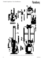
Turbodisk Applicator - Parts Identification
Figure 8: 70990-06 Turbodisk Assembly, 3-Way Valves
37
AA-07-02.1
Turbodisk Applicator - Parts Identification
70990-06 TURBODISK ASSEMBLY, 3-WAY VALVES - PARTS LIST (Figure 8)
Item #
1
Part #
70976-01
Description
Feed Tube Kit, Downfeed
Qty
1
Notes
Part of 70988-XX Kit
These parts are supplied with Kit 70973-01 Hardware & Mounting Parts Kit
2-1
8156-24F
Screw, 5/16-24 X 3/4", Hex Head
2
2-2
8156-32F
Screw, 5/16-24 X 1", Hex Head
5
2-3
8156-40F
Screw, 5/16-24 X 1-1/4", Heax Head
1
2-4
7734-07
L Washer, Spring, 5/16"
6
2-9
15980-00
Extension Arm, Air Motor
1
2-10
1613-03
Tube Support, 20-3/8"
1
2-11
8156-48F
Screw, 5/16-24 X 1-1/2", Hex Head (Not Used)
2
2-13
27141-081
Hose Wrapping (Not Shown)
25'
Same TR-SSEM-082
2-14
15946-00
Grounding Hook Assembly (Not Shown)
1
2-15
10384-01
Tubing, Latex, 3/16" ID X 1/16" Wall (Not Shown)
50'
5-1 parts
17274-00
HighKit
Voltage
Connector
Assembly
These
are supplied with
70977-04
(3/8" OD)
Low Flow or 70977-05 (1/2" OD)1High
Flow, Tube & Fitting Kit (Shipped loose as Kit, no assembly)
3-1
9704-03
Tubing, LD/PE, 1/4" OD X .17" ID
100'
3-2
7113-13
Tubing, 1/2" OD X .060" Wall, Nylon
50'
3-3
SSP-5020
Tubing, 3/8" OD X 1/4" ID
100' Supplied with Kit 70977-04 only
3-3
55994-26
Tubing, 1/2" OD X 3/8" ID
100' Supplied with Kit 70977-05 only
3-4
41-FTC-1002 Fitting, Connector, 3/8" T X 1/4" NPT
4
Supplied with Kit 70977-04 only
3-4
LSFI0005-01 Connector, Straight, 1/2" OD Tube X 1/4" NPT
4
Supplied with Kit 70977-05 only
3-5 parts
78006-00
Elbow
2
These
are supplied with
Kit 70975-05, 3-Way Valve Kit
4-1
4-2
4-3
4-4
4-6
4-7
4-8
4-9
4-10
4-11
4-12
4-13
4-14
AA-07-02.1
LSFI0004-01
LSFI0006-01
SSV-809
55994-23
18283-02
LSFI0009-01
SSP-39
SSP-6427
70590-01
8156-48F
7734-07
17366-00
LSFI0018-01
Street Tee, 1/4" NPT, SS
Elbow, 1/4" OD Tube X 1/4" NPT Female, SS Check Valve, 1/4" NPT, SS
Tubing, FEP, .156" ID X .25" OD
Valve Assembly, 3-Way
Elbow, Street, 1/4" NPT, SS
Reducer, 1/8" NPT, Male X 1/4" NPT, Female, SS
Elbow, 1/4" OD Tube X 1/8" NPT, Brass
Connector, Male, 1/4" OD Tube X 1/4" NPT, SS
Screw, 5/16-32 X 1-1/4" Lg., Hex Head
L Washer, 5/16"
Repair Kit, 3-Way Valve (Not Shown)
Ferrule Kit (Not Shown)
1
1
1
5'
1
1
2
1
2
2
2
1
1
38
Turbodisk Applicator - Parts Identification
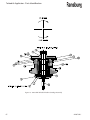
Figure 9: 70990-07 Turbodisk Assembly, Trigger Valve Only
39
AA-07-02.1
Turbodisk Applicator - Parts Identification
70990-07 TURBODISK ASSEMBLY, TRIGGER VALVE ONLY - PARTS LIST (Figure 9)
Item #
1
Part #
70976-01
Description
Feed Tube Kit, Downfeed
Notes
Qty
1
Part of 70988-XX Kit
These parts are supplied with Kit 70973-01 Hardware & Mounting Parts Kit
2-1
8156-24F
Screw, 5/16-24 X 3/4", Hex Head
2
2-2
8156-32F
Screw, 5/16-24 X 1", Hex Head
5
2-3
8156-40F
Screw, 5/16-24 X 1-1/4", Heax Head
1
2-4
7734-07
L Washer, Spring, 5/16"
6
2-9
15980-00
Extension Arm, Air Motor
1
2-10
1613-03
Tube Support, 20-3/8"
1
2-11
8156-48F
Screw, 5/16-24 X 1-1/2", Hex Head (Not Used)
2
2-13
27141-081
Hose Wrapping (Not Shown)
25'
Same TR-SSEM-082
2-14
15946-00
Grounding Hook Assembly (Not Shown)
1
2-15
10384-01
Tubing, Latex, 3/16" ID X 1/16" Wall (Not Shown)
50'
5-1 parts17274-00
HighKit
Voltage
Connector
Assembly
These
are supplied with
70977-04
(3/8" OD)
Low Flow or 70977-05 (1/2" OD)1High
Flow, Tube & Fitting Kit (Shipped loose as Kit, no assembly)
3-1
9704-03
Tubing, LD/PE, 1/4" OD X .17" ID
100'
3-2
7113-13
Tubing, 1/2" OD X .060" Wall, Nylon
50'
3-3
SSP-5020
Tubing, 3/8" OD X 1/4" ID
100' Supplied with Kit 70977-04 only
3-3
55994-26
Tubing, 1/2" OD X 3/8" ID
100'
Supplied with Kit 70977-05 only
3-4
41-FTC-1002 Fitting, Connector, 3/8" T X 1/4" NPT
4 Supplied with Kit 70977-04 only
3-4
LSFI0005-01 Connector, Straight, 1/2" OD Tube X 1/4" NPT
4 Supplied with Kit 70977-05 only
3-5
78006-00
Elbow
2
These parts are supplied with Kit 70975-07 (High Flow) of 70975-09 (Low Flow) Trigger Valve
W/Regulator or Regulator Ready
* Indicates supplied W/70975-07 Only. ** Indicates supplied W/70975-09 Only
4-1
4-2
4-3
4-4
4-5
4-6
4-7
4-8
4-8
4-9
4-10
4-11
4-12
4-13
4-14
4-15
3
70590-01
LSFI0038-00
76462-00
LRPM0105
CCV-12-SS
CCV-403-SS
SSP-6054
55994-23
55994-24
SSP-1421
7958-56C
7734-06
78004-00 78006-00
SSP-6439
LSFI0007-01
Connector, Male, 1/4" OD Tube X 1/4" NPT, SS
Elbow, SST, 1/4" NPT(F) X 1/8" NPT(M)
Fitting, SST, 1/4" NPT, Male, Branch Tee
Bracket
Valve Adapter
Trigger Valve Assembly
Connector, 1/4" OD Tube X 1/8" NPT, Male, Brass
Tubing, FEP, .250" OD X .156" ID
Tubing, FEP, .250 OD X .126 ID
Plug, Hex Socket, 1/4" NPT
Screw, 1/4-20 X 1-3/4" Lg., Hex Head
L Washer, 1/4"
Bushing, 1/2" NPT Male X 1/4" NPT Female, SS *
Elbow, Street, 1/4" NPT, SS
Elbow, Swivel, Male, 1/4" OD X 1/4" NPT, Brass Elbow, 1/4" OD Tube X 1/4" NPT Male, SS *
1
1
1
1
1
1
1
5'
5'
1
2
4
2
2
1
2
3
3
Use as required to increase fluid pressure at regulator outlet to approx. 5-20 psi
Pressue Change Across Tubing (PSI) ≈ .601 X 106 X Flow Rate (mi/min) X Viscosity (Poise) X Fluid Length (in)
[Tube ID (in)]4
(Continued On Next Page)
AA-07-02.1
40
Turbodisk Applicator - Parts Identification
70990-07 TURBODISK ASSEMBLY, TRIGGER VALVE ONLY - PARTS LIST (Continued)
(Figure 9)
Item #
Part #
Description
Qty
Notes
These parts are supplied with Kit 70975-07 (High Flow) of 70975-09 (Low Flow) Trigger Valve
W/Regulator or Regulator Ready
* Indicates supplied W/70975-07 Only. ** Indicates supplied W/70975-09 Only
4-17
SSV-809
4-18
70171-04
4-18
74151-XX
4-18
70589-05
4-18
8212-32F
4-18
7787-02
4-18
LSFI0004-04
4-19
SSF-8125
4-20
20810-00
4-20
LSMM0025
4-21
LSFI0018-01
4-22
AU-81-07
4-22
LN-9223-00.9
4-23
KK-4841
4-24
LN-9100-00
4-25
CCV-7
41
Check Valve, 1/4" NPT
Flow Regulator Assembly *
Flow Regulator, DR-1 (Not Shown) **
Fitting, 1/4" OD Tube, Special (Not Shown) **
Screw, Regulator Mounting (Not Shown) **
Adapter, 1/4" NPSF to 1/4" NPTF, Carbon Steel **
(Not Shown)
Tee, Street, 1/4" NPT (Not Shown) ** Hex Jam Nut
Bracket, Regulator *
Bracket, DR-1 (Not Shown) **
Ferrule Kit (Not Shown)
Flow Regulator Service Manual - 70171-04 (Not Shown) *
DR-1 Fluid Regulator Service Manual - 74151-XX (Not Shown) **
Repair Kit, CCV-403-SS (Not Shown)
CCV-403-SS Service Manual (Not Shown)
Valve Tool (Not Shown)
1
1
1
1
2
1
1
1
1
1
1
1
1
1
1
1
AA-07-02.1
Turbodisk Applicator - Parts Identification
NOTES
AA-07-02.1
42
Turbodisk Applicator - Parts Identification
Figure 10: 70990-08 Turbodisk Assembly, Trigger and Dump Valve
43
AA-07-02.1
Turbodisk Applicator - Parts Identification
70990-08 TURBODISK ASSEMBLY, TRIGGER AND DUMP VALVE - PARTS LIST (Figure
10)
Item #
1
Part #
70976-01
Description
Feed Tube Kit, Downfeed
Notes
Qty
1
Part of 70988-XX Kit
These parts are supplied with Kit 70973-01 Hardware & Mounting Parts Kit
2-1
8156-24F
Screw, 5/16-24 X 3/4", Hex Head
2
2-2
8156-32F
Screw, 5/16-24 X 1", Hex Head
5
2-3
8156-40F
Screw, 5/16-24 X 1-1/4", Heax Head
1
2-4
7734-07
L Washer, Spring, 5/16"
6
2-9
15980-00
Extension Arm, Air Motor
1
2-10
1613-03
Tube Support, 20-3/8"
1
2-11
8156-48F
Screw, 5/16-24 X 1-1/2", Hex Head (Not Used)
2
2-13
27141-081
Hose Wrapping (Not Shown)
25'
Same as TR-SSEM-082
2-14
15946-00
Grounding Hook Assembly (Not Shown)
1
2-15
10384-01
Tubing, Latex, 3/16" ID X 1/16" Wall (Not Shown)
50'
5-1 parts
17274-00
HighKit
Voltage
Connector
Assembly
These
are supplied with
70977-04
(3/8" OD)
Low Flow or 70977-05 (1/2" OD)1High
Flow, Tube & Fitting Kit (Shipped loose as Kit, no assembly)
3-1
9704-03
Tubing, LD/PE, 1/4" OD X .17" ID
100'
3-2
7113-13
Tubing, 1/2" OD X .060" Wall, Nylon
50'
3-3
SSP-5020
Tubing, 3/8" OD X 1/4" ID
100' Supplied with Kit 70977-04 only
3-3
55994-26
Tubing, 1/2" OD X 3/8" ID
100' Supplied with Kit 70977-05 only
3-4
41-FTC-1002 Fitting, Connector, 3/8" T X 1/4" NPT
4 Supplied with Kit 70977-04 only
3-4
LSFI0005-01 Connector, Straight, 1/2" OD Tube X 1/4" NPT
4 Supplied with Kit 70977-05 only
3-5
78006-00
Elbow
2
These parts are supplied with Kit 70975-08 (High Flow) or 70975-10 (Low Flow) Trigger and Dump Valve W/Regulator
Ready
* Indicates supplied w/70975-08 only. ** Indicates supplied w/70975-10 only.
4-1
4-2
4-3
4-4
4-5
4-6
4-7
4-8
4-8
4-9
4-10
4-11
3
70590-01
LSFI0038-00
76462-00
LRPM0105
CCV-12-SS
LDSK4000
SSP-6054
55994-23
55994-24
SSP-1421
7958-56C
7734-06
Connector, Male, 1/4" OD Tube X 1/4" NPT, SS
Elbow, SST, 1/4" NPT(F) X 1/8" NPT(M)
Fitting, SST, 1/4" NPT, Male, Branch Tee
Bracket
Valve Adapter
2-Valve Assembly, Trigger and Dump
Connector, 1/4" OD Tube X 1/8" NPT, Male, Brass
Tubing, FEP, .250" OD X .156" ID
Tubing, FEP, .250 OD X .126 ID
Plug, Hex Socket, 1/4" NPT
Screw, 1/4-20 X 1-3/4" Lg., Hex Head
L Washer, 1/4"
1
1
1
1
1
1
1
5'
5'
1
2
4
3
3
Use as required to increase fluid pressure at regulator outlet to approx. 5-20 psi
Pressue Change Across Tubing (PSI) ≈ .601 X 106 X Flow Rate (mi/min) X Viscosity (Poise) X Fluid Length (in)
[Tube ID (in)]4
(Continued On Next Page)
AA-07-02.1
44
Turbodisk Applicator - Parts Identification
70990-08 TURBODISK ASSEMBLY, TRIGGER AND DUMP VALVE - PARTS LIST (Cont.)
(Figure 10)
Item #
Part #
Description
Qty
Notes
These parts are supplied with Kit 70975-08 (High Flow) or 70975-10 (Low Flow) Trigger and Dump Valve W/Regulator or
Regulator Ready.
* Indicates supplied w/70975-08 only. ** Indicates supplied w/70975-10 only.
4-13
78006-00
4-14
SSP-6439
4-15
LSFI0007-01
4-16
LSFI0006-01
4-17
SSV-809
4-18
70171-04
4-18
74151-XX
4-18
70589-05
4-18
8212-32F
4-18
7787-02
4-18
LSFI0004-01
4-19
SSF-8125
4-20
20810-00
4-20
LSMM0025
4-21
LSFI0018-01
4-22
AU-81-07
4-23
KK-4841
4-24
LN-9100-00
4-25
CCV-7
3
45
Elbow, Street, 1/4" NPT, SS
Elbow, Swivel, Male, 1/4" OD X 1/4" NPT, Brass * Elbow, 1/4" OD Tube X 1/4" NPT Male, SS Elbow, 1/4" OD Tube X 1/4" NPT Female, SS
Check Valve, 1/4" NPT
Flow Regulator Assembly (Reference) *
Dlow Regulator, DR-1 (Not Shown) **
Fitting, 1/4" OD Tube, Special (Not shown) **
Screw, Regulator Mounting (Not Shown) **
Adapter, 1/4" NPSF to 1/4" NPTF, Carbon Steel (Not Shown) **
Tee, Street, 1/4" NPT (Not Shown) **
Hex Jam Nut
Bracket, Regulator *
Bracket, DR-1 **
Ferrule Kit (Not Shown)
Flow Regulator Service Manual,
70174-04 (Not Shown) *
Repair Kit, CCV-403-SS (Not Shown)
CCV-403-SS Service Manual (Not Shown)
Valve Tool (Not Shown)
2
1
2
1
1
1
1
1
2
1
1
1
1
1
1
1
1
1
1
Use as required to increase fluid pressure at regulator outlet to approx. 5-20 psi
Pressue Change Across Tubing (PSI) ≈ .601 X 106 X Flow Rate (mi/min) X Viscosity (Poise) X Fluid Length (in)
[Tube ID (in)]4
AA-07-02.1
Turbodisk Applicator - Parts Identification
NOTES
AA-07-02.1
46
Turbodisk Applicator - Parts Identification
Figure 11: 70990-09 Turbodisk Assembly, Trigger Valve Only W/DR-1 Regulator
47
AA-07-02.1
Turbodisk Applicator - Parts Identification
70990-09 TURBODISK ASSEMBLY, TRIGGER VALVE ONLY
W/DR-1 REGULATOR - PARTS LIST (Figure 11)
Item #
1
Part #
70976-01
Description
Feed Tube Kit, Downfeed
Notes
Qty
1
Part of 70988-XX Kit
These parts are supplied with Kit 70973-01 Hardware & Mounting Parts Kit
2-1
8156-24F
Screw, 5/16-24 X 3/4", Hex Head
2
2-2
8156-32F
Screw, 5/16-24 X 1", Hex Head
5
2-3
8156-40F
Screw, 5/16-24 X 1-1/4", Heax Head
1
2-4
7734-07
L Washer, Spring, 5/16"
6
2-5
17274-00
High Voltage Connector Assembly
1
2-9
15980-00
Extension Arm, Air Motor
1
2-10
1613-03
Tube Support, 20-3/8"
1
2-11
8156-48F
Screw, 5/16-24 X 1-1/2", Hex Head (Not Used)
2
2-12
3923-02
Spiral Wrap, 1/2" (Not Shown)
25'
2-13
27141-081
Hose Wrapping (Not Shown)
25'
Same as TR-SSEM-082
2-14
15946-00
Grounding Hook Assembly (Not Shown)
1
2-15
10384-01
Tubing, Latex, 3/16" ID X 1/16" Wall (Not Shown)
50'
These parts are supplied with Kit 70977-04 (3/8" OD) Low Flow or 70977-05 (1/2" OD) High
Flow, Tube & Fitting Kit (Shipped loose as Kit, no assembly)
3-1
9704-03
Tubing, LD/PE, 1/4" OD X .17" ID
100'
3-2
7113-13
Tubing, 1/2" OD X .060" Wall, Nylon
50'
3-3
SSP-5020
Tubing, 3/8" OD X 1/4" ID
100'
3-3
55994-26
Tubing, 1/2" OD X 3/8" ID
100'
3-4
78006-00
Elbow, 3/8" OD Tube X 1/4" NPT 2
3-4
LSFI0005-01 Connector, Straight, 1/2" OD Tube X 1/4" NPT
4
3-5
41-FTC-1002 Connector, Straight, 3/8" OD Tube X 1/4" NPT
4
Supplied with Kit 70977-04 only
Supplied with Kit 70977-05 only
Supplied with Kit 70977-04
only Supplied with Kit 70977-05 only
These parts are supplied with Kit 70975-09 Trigger Valve Kit
4-1
70590-01
4-4
LRPM0105
4-5
CCV-12-SS
4-6
CCV-403-SS
4-7
SSP-6054
4-8
55994-28
4-9
SSP-1421
4-13
LSFI0038-00
4-14
SSP-6439
4-15
76462-00
4-16
LSFI0006-01
3
Connector, Male, 1/4" OD Tube X 1/4" NPT, SS
Bracket
Valve Adapter
Trigger Valve Assembly
Connector, 1/4" OD Tube X 1/8" NPT, Male, Brass
Tubing, FEP, .188" ID X .250" OD
Plug, Hex Socket, 1/4" NPT
Elbow, Street, Reducing, 1/8" NPTM X 1/4" NPTF, SS
Elbow, Swivel, Male, 1/4" OD X 1/4" NPT, Brass
Service Tee, NI, 1/4"
Elbow, 1/4" OD Tube X 1/4" NPT,Female, SS
1
1
1
1
1
5'
1
2
1
1
1
Use as required to increase fluid pressure at regulator outlet to approx. 5-20 psi
Pressue Change Across Tubing (PSI) ≈ .601 X 106 X Flow Rate (mi/min) X Viscosity (Poise) X Fluid Length (in)
[Tube ID (in)]4
(Continued On Next Page)
AA-07-02.1
48
Turbodisk Applicator - Parts Identification
70990-09 TURBODISK ASSEMBLY, TRIGGER VALVE ONLY
W/DR-1 REGULATOR - PARTS LIST (Cont.) (Figure 11)
Item #
Part #
Description
Notes
Qty
These parts are supplied with Kit 70975-09 Trigger Valve Kit
4-18
4-19
4-20
4-21
4-22
4-23
4-24
4-25
4-26
4-27
4-28
4-29
4-30
LSFI0007-01
SSF-8125
LSMM0025-00
LSFI0018-01
LN-9223-00.9
KK-4841
LN-9100-00
CCV-7
55994-23
55994-24
7787-02
70589-05
8212-32F
Elbow, Male, SS
Hex Jam Nut
Bracket, Regulator
Ferrule, Kit (Not Shown)
DR-1 Fluid Regulator Service Manual (Not Shown)
Repair Kit, CCV-403-SS (Not Shown)
CCV-302-SS Service Manual
Valve Tool (Not Shown)
Tubing, .156" ID X .253" OD
Tubing, 1/4" OD X 1/8" ID
Adapter, 1/4" NPSF to NPTF, Carbon Steel
Fitting, Paint, .250" Dia.
Screw, Cap, Hex Socket, #10-32
1
1
1
1
1
1
1
1
5'
5'
1
1
2
3
3
Use as required to increase fluid pressure at regulator outlet to approx. 5-20 psi
Pressue Change Across Tubing (PSI) ≈ .601 X 106 X Flow Rate (mi/min) X Viscosity (Poise) X Fluid Length (in)
[Tube ID (in)]4
3
49
AA-07-02.1
Turbodisk Applicator - Parts Identification
NOTES
AA-07-02.1
50
Turbodisk Applicator - Parts Identification
Figure 12: 70990-10 Turbodisk Assembly, Trigger and Dump Valve with DR-1 Regulator
51
AA-07-02.1
Turbodisk Applicator - Parts Identification
70990-10 TURBODISK ASSEMBLY, TRIGGER AND DUMP VALVE
W/DR-1 REGULATOR - PARTS LIST (Figure 12)
Item #
1
Part #
70976-01
Description
Feed Tube Kit, Downfeed
Notes
Qty
1
Part of 70988-XX Kit
These parts are supplied with Kit 70973-01 Hardware & Mounting Parts Kit
2-1
8156-24F
2-2
8156-32F
2-3
8156-40F
2-4
7734-07
2-5
17274-00
2-9
15980-00
2-10
1613-03
2-11
8156-48F
2-13
27141-081
Same as TR-SSEM-082
2-14
15946-00
2-15
10384-01
Screw, 5/16-24 X 3/4", Hex Head
Screw, 5/16-24 X 1", Hex Head
Screw, 5/16-24 X 1-1/4", Heax Head
L Washer, Spring, 5/16"
High Voltage Connector Assembly
Extension Arm, Air Motor
Tube Support, 20-3/8
Screw, 5/16-24 X 1-1/2", Hex Head (Not Used)
Hose Wrapping (Not Shown)
2
5
1
6
1
1
1
2
25'
Grounding Hook Assembly (Not Shown)
Tubing, Latex, 3/16" ID X 1/16" Wall (Not Shown)
1
50'
These parts are supplied with Kit 70977-04 (3/8" OD) Low Flow or 70977-05 (1/2" OD) High
Flow, Tube & Fitting Kit (Shipped loose as Kit, no assembly)
3-1
9704-03
Tubing, LD/PE, 1/4" OD X .17" ID
100'
3-2
7113-13
Tubing, 1/2" OD X .060" Wall, Nylon
50'
3-3
SSP-5020
Tubing, 3/8" OD X 1/4" ID
100'
3-3
55994-26
Tubing, 1/2" OD X 3/8" ID
100'
3-4
78006-00
Elbow, 3/8" OD Tube X 1/4" NPT 2
3-4
LSFI0005-01 Connector, Straight, 1/2" OD Tube X 1/4" NPT
4
3-5
41-FTC-1002 Connector, Straight, 3/8" OD Tube X 1/4" NPT
4
Supplied with Kit 70977-04 only
Supplied with Kit 70977-05 only
Supplied with Kit 70977-04
only Supplied with Kit 70977-05 only
These parts are supplied with Kit 70975-10 Trigger Valve Kit
4-1
70590-01
4-4
LRPM0105
4-5
CCV-12-SS
4-6
LDSK4000
4-7
SSP-6054
4-8
55994-23
4-9
SSP-1421
4-13
LSFI0038-00
4-15
76462-00
4-16
LSFI0006-01
4-17
SSV-809
4-18
LSFI0007-01
3
Connector, Male, 1/4" OD Tube X 1/4" NPT, SS
Bracket
Valve Adapter
2-Valve Assembly, Trigger and Dump
Connector, 1/4" OD Tube X 1/8" NPT, Male, Brass
Tubing, FEP, .188" ID X .250" OD
Plug, Hex Socket, 1/4" NPT
Elbow, Street, Reducing, 1/8" NPTM X 1/4" NPTF, SS
Service Tee, NI, 1/4"
Elbow, 1/4" OD Tube X 1/4" NPT,Female, SS
Check Valve, 1/4" NPT
Elbow, Male, SS
1
1
1
1
1
5'
1
2
1
1
1
1
Use as required to increase fluid pressure at regulator outlet to approx. 5-20 psi
Pressue Change Across Tubing (PSI) ≈ .601 X 106 X Flow Rate (mi/min) X Viscosity (Poise) X Fluid Length (in)
[Tube ID (in)]4
(Continued On Next Page)
AA-07-02.1
52
Turbodisk Applicator - Parts Identification
70990-10 TURBODISK ASSEMBLY, TRIGGER AND DUMP VALVE
W/DR-1 REGULATOR - PARTS LIST (Cont.) (Figure 12)
Item #
Part #
Description
Notes
Qty
These parts are supplied with Kit 70975-10 Trigger Valve Kit
4-20
4-21
4-22
4-23
4-24
4-25
4-26
4-27
4-28
4-29
4-30
3
53
LSMM0025-00
LSFI0018-01
LN-9223-00.9
KK-4841
LN-9100-00
CCV-7
55994-23
55994-24
7787-02
70589-05
8212-32F
Bracket, Regulator
Ferrule Kit (Not Shown)
DR-1 Fluid Regulator Service Manual (Not Shown)
Repair Kit, CCV-403-SS (Not Shown)
CCV-403-SS Service Manual (Not Shown)
Valve Tool (Not Shown)
Tubing, .156" IDX .253" OD
Tubing, 1/4" OD X 1/8" ID
Adapter, 1/4" NPSF to NPTF, Carbon Steel
Fitting, Paint, .250" Dia.
Screw, Cap, Hex Socket, #10-32
1
1
1
1
1
1
5'
5'
1
1
2
3
3
Use as required to increase fluid pressure at regulator outlet to approx. 5-20 psi
Pressue Change Across Tubing (PSI) ≈ .601 X 106 X Flow Rate (mi/min) X Viscosity (Poise) X Fluid Length (in)
[Tube ID (in)]4
AA-07-02.1
Turbodisk Applicator - Parts Identification
NOTES
AA-07-02.1
54
Turbodisk Applicator - Parts Identification
Figure 13: 70990-11 Turbodisk Assembly, Dual DR-1 Regulators
55
AA-07-02.1
Turbodisk Applicator - Parts Identification
70990-11 TURBODISK ASSEMBLY, DUAL DR-1 REGULATORS - PARTS LIST (Figure 13)
Item #
1
Part #
70976-01
Description
Feed Tube Kit, Downfeed
Notes
Qty
1
Part of 70988-XX Kit
These parts are supplied with Kit 70973-01 Hardware & Mounting Parts Kit
2-1
8156-24F
2-2
8156-32F
2-3
8156-40F
2-4
7734-07
2-5
17274-00
2-9
15980-00
2-10
1613-03
2-11
8156-48F
2-13
27141-081
Same as TR-SSEM-082
2-14
15946-00
2-15
10384-01
Screw, 5/16-24 X 3/4", Hex Head
Screw, 5/16-24 X 1", Hex Head
Screw, 5/16-24 X 1-1/4", Heax Head
L Washer, Spring, 5/16"
High Voltage Connector Assembly
Extension Arm, Air Motor
Tube Support, 20-3/8"
Screw, 5/16-24 X 1-1/2", Hex Head (Not Used)
Hose Wrapping (Not Shown)
2
5
1
6
1
1
1
2
25'
Grounding Hook Assembly (Not Shown)
Tubing, Latex, 3/16" ID X 1/16" Wall (Not Shown)
1
50'
These parts are supplied with Kit 70977-04 (3/8" OD) Low Flow or 70977-05 (1/2" OD) High
Flow, Tube & Fitting Kit (Shipped loose as Kit, no assembly)
3-1
9704-03
Tubing, LD/PE, 1/4" OD X .17" ID
100'
3-2
7113-13
Tubing, 1/2" OD X .060" Wall, Nylon
50'
3-3
SSP-5020
Tubing, 3/8" OD X 1/4" ID
100'
3-3
55994-26
Tubing, 1/2" OD X 3/8" ID
100'
3-4
78006-00
Elbow, 3/8" OD Tube X 1/4" NPT 2
3-4
LSFI0005-01
Connector, Straight, 1/2" OD Tube X 1/4" NPT
4
3-5
41-FTC-1002
Connector, Straight, 3/8" OD Tube X 1/4" NPT
4
Supplied with Kit 70977-04 only
Supplied with Kit 70977-05 only
Supplied with Kit 70977-04
only Supplied with Kit 70977-05 only
These parts are supplied with Kit 70975-11 Trigger Valve Kit
4-1
4-2
4-3
4-4
4-5
4-6
4-7
4-8
4-9
4-15
4-16
4-17
4-19
3
70590-01
76462-00
LSFI0038-00
LRPM0105
CCV-12-SS
LDSK4000
SSP-6054
55994-28
SSP-1421
LSFI0007-01
LSFI0006-01
SSV-809
SSF-8125
Connector, Male, 1/4" OD Tube X 1/4" NPT, SS
Tee, 1/4" NPT (X2) X 1/4" NPTM, SS
Elbow, 1/4" NPTF X 1/8" NPTM, SS
Bracket
Valve Adapter
2-Valve Assembly, Trigger and Dump
Connector, 1/4" OD Tube X 1/8" NPT, Male, Brass
Tubing, FEP, .188" ID X .250" OD
Plug, Hex Socket, 1/4" NPT
Elbow, Male, SS
Elbow, 1/4" OD Tube X 1/4" NPT,Female, SS
Check Valve, 1/4" NPT
Hex Jam Nut
2
2
2
2
2
2
2
5'
2
2
2
2
2
Use as required to increase fluid pressure at regulator outlet to approx. 5-20 psi
Pressue Change Across Tubing (PSI) ≈ .601 X 106 X Flow Rate (mi/min) X Viscosity (Poise) X Fluid Length (in)
[Tube ID (in)]4
(Continued On Next Page)
AA-07-02.1
56
Turbodisk Applicator - Parts Identification
70990-11 TURBODISK ASSEMBLY, DUAL DR-1 REGULATORS - PARTS LIST (Cont.)
(Figure 13)
Item #
Part #
Description
Qty
Notes
These parts are supplied with Kit 70975-11 Trigger Valve Kit
4-21
4-22
4-23
4-24
4-25
4-26
4-27
4-28
4-29
4-30
3
57
LSFI0018-01
LN-9223-00.9
KK-4841
LN-9100-00
CCV-7
55994-23
55994-24
7787-02
70589-05
8212-32F
Ferrule Kit (Not Shown)
DR-1 Fluid Regulator Service Manual (Not Shown)
Repair Kit, CCV-403-SS (Not Shown)
CCV-403-SS Service Manual (Not Shown)
Valve Tool (Not Shown)
Tubing, .156" IDX .253" OD
Tubing, 1/4" OD X 1/8" ID
Adapter, 1/4" NPSF to NPTF, Carbon Steel
Fitting, Paint, .250" Dia.
Screw, Cap, Hex Socket, #10-32
2
1
1
1
1
10'
10'
2
2
4
3
3
Use as required to increase fluid pressure at regulator outlet to approx. 5-20 psi
Pressue Change Across Tubing (PSI) ≈ .601 X 106 X Flow Rate (mi/min) X Viscosity (Poise) X Fluid Length (in)
[Tube ID (in)]4
AA-07-02.1
Turbodisk Applicator - Parts Identification
NOTES
AA-07-02.1
58
Turbodisk Applicator - Parts Identification
Figure 14: 78170-00 Drive Air Regulator Assembly
78170-00 DRIVE AIR REGULATOR ASSEMBLY - PARTS LIST (Figure 14)
Item #
1
2
3
4
5
6
7
8
9
10
11
12
13
14
Part #
SSP-6439
A11596-00
A11595-00
SSP-6819
LS0147
--
GA-316
41-FP-1021
HAF-503
--
--
--
11021-23
--
Description
Elbow, 1/4" OD Tube X 1/4" NPT, Male Swivel
Fitting, 3/4" NPT X SAE 45°, Male Connector
Regulator, 3/4" NPT Ported, Air Piloted
Tube Fitting
Regulator, 1" Ported, Manual Adjust Air
--
Gauge, 0-160 PSIG, 1/4" NPT, Air
Nipple, 1" NPT X 3/4" NPT, Hex Reducing
Air Filter, 3/4" NPT
--
--
--
Plug, 1/4" NPT Pipe --
Qty
1
1
1
1
1
-1
2
1
---Ref.
--
Apply 7969-10 Thread Sealer to all pipe threads prior to assembly.
59
AA-07-02.1
Turbodisk Applicator - Parts Identification
Figure 15: 78166-00 Compressed Air Hose Assembly
78166-00 COMPRESSED AIR HOSE ASSEMBLY - PARTS LIST (Figure 15)
Item #
1
2
1
Part #
78164-00
78165-00
Description
Hose, 3/4" ID , Push-Lok Air
Fitting, Female SAE 45° Swivel X 3/4" ID Hose
Qty
5'
2
Lubricate the fitting and/or hose ID with soapy water only. DO NOT use heavy oil or grease.
AA-07-02.1
60
Turbodisk Applicator - Parts Identification
Figure 16: 78781-00 Air Heater and Regulator Assembly
61
AA-07-02.1
Turbodisk Applicator - Parts Identification
78781-00 AIR HEATER AND REGULATOR ASSEMBLY PARTS LIST (Figure 16)
Item #
1
2
3
4
Part #
78170-00
78166-00
A11065-05
78176-01
!
>
Description
Regulator Assembly, Turbodisk Drive Air
Hose Assembly, Compressed Air
Air Heater Assembly
Tubing, 1/2" OD X .375" ID, Green Nylon
Qty
1
1
1
200 ft.
1
WARNING
The air heater assembly must be
located outside of any hazardous areas as
defined by the NFPA-33.
1
AA-07-02.1
62
Turbodisk Applicator - Parts Identification
Figure 17: 70158-00 Fairing Assembly
63
AA-07-02.1
Turbodisk Applicator - Parts Identification
70158-00 FAIRING ASSEMBLY - PARTS LIST (Figure 17)
Item #
1
2
3
4
5
6
7
8
9
1
Part #
70157-02
70155-02
70381-00
70909-00
8156-32F
7734-07
70656-32C
20559-09
AU-81-02.1
Description
Fairing
Bulkhead
Flange Support
Plug, Machined, Feed Tube Adjustment
Screw, 5/16-24 X 1" Lg. Hex Head
Lock Washer, 5/16" Helical Spring
Screw, Nylon, 3/8-16 X 1" Lg. Hex Head
Washer, Nylon, Flat, 3/8" ID
Service Literature (Not Shown)
Qty
1
1
1
2
2
2
6
6
1
1
1
On up-feed assemblies, use 70913 (Ref.) feed tube bracket (1 Required) & 70914-01 (Ref.)
clockwise feed tube or 70914-02 (Ref.) counter-clockwise feed tube on air motor.
AA-07-02.1
64
Turbodisk Applicator - Parts Identification
Figure 18: 78175-XX Turbodisk Air Turbine Assembly
65
AA-07-02.1
Turbodisk Applicator - Parts Identification
78175-XX TURBODISK AIR TURBINE ASSEMBLY PARTS LIST (Figure 18)
Item #
1
2
3
4
5
6
7
8
9
10
11
12
13
14
Description
Part #
Qty
Housing Assembly, Machined, Turbodisk Upgrade
Screw, #8-32 x 5/16" Long, Slotted Round Head
Lock Washer, #8 Helical Spring
Plug, Protective
Muffler, 1" NPT Polyethylene Exhaust
Fitting, Machined, Exhaust Muffler Adapter
Identification Cap, 1/2" OD Tube, Green
Fitting, 1/2" NPT x 1/2" OD Tube
O-Ring, 4.239" ID x .070" CS, Solvent Resistant
Screw, #8-32 x 3/8" Long, Socket Head Set
Air Motor Assembly, Turbodisk
Screw, #6-32 x 1/2" Long, Socket Head Cap
Nameplate, Turbodisk
Drive Screw
78174-00
7735-10C
7734-03
LS0135
78163-00
78173-00
78169-00
78168-00
7554-74
7716-12C
B*
10773-16C
70870-00
7612-43
1
8
8
1
1
A*
2
2
2
3
1
6
1
4
2
3
5
* See corresponding column in Table "A"
TABLE "A" (Figure 18)
Part #
78175-01
78175-02
78175-11
78175-12
Description
A
B
Air Motor Assembly, Clockwise Rotation, without Exhaust Adapter
Air Motor Assembly, Counter-Clockwise Rotation, with Exhaust Adapter
Air Motor Assembly, Counter-Clockwise Rotation, without Exhaust Adapter
Air Motor Assembly, Counter-Clockwise Rotation, with Exhaust Adapter
0
1
0
1
70879-406
70879-406
70879-456
70879-456
1
1
**See "Parts List Bullet Definition Table"
** PARTS LIST BULLET DEFINITION TABLE (Figure 18)
5
Tighten screws alternately to a final torque reading of 10 lbs•in (1.13 Nm).
3
Apply Petrolatum jell, SSL-11, to o-rings prior to assembly.
2
Apply 7969-10 thread sealer to male pipe threads prior to assembly.
1
The exhaust adapter is required only when the orientation of the fluid valving will not allow the exhaust muffler
to be installed directly into the turbine housing. If the installed system provides an interference, then it may be
possible to re-orient the fluid valving so that the exhaust adapter is not required.
AA-07-02.1
66
Turbodisk Applicator - Parts Identification
Figure 19: 70879-XXX Turbodisk Turbine Cartridge Assembly
67
AA-07-02.1
Turbodisk Applicator - Parts Identification
70879-XXX TURBODISK TURBINE CARTRIDGE ASSEMBLY PARTS LIST (Figure 19)
Item #
1
2
3
4
5
6
7
8
9
10
11
12
13
14
15
16
17
18
Description
Part #
Qty
Retainer, Bearing
Screw, #6-32 x 3/8" Long, Hex Socket, Flat Head
Slinger
Spacer, Bearing
Bearing, Ball
O-Ring, 1.614" ID, Solvent Resistant
O-Ring, 3.489" ID, Solvent Resistant
Decal, 20292-xx Turbodisk
Key, Woodruff, 1/2" Dia.
Nut, Self-Lock, 5/8-18, UNF
Seat, Spring
Spring, Compression
Screw, Set, Special
Housing, Bearing, Machined
O-Ring, 2.239" ID, Solvent Resistant
Plate, Nozzle
Rotor, Turbine
Shaft, Air Motor
70873-00
78232-12C
70876-00
20298-00
70896-00
7554-77
7554-73
73180-02
8310-01
7729-10
20966-00
70868-00
70871-00
70875-00
7554-17
A*
B*
C*
1
12
1
1
2
1
1
1
1
1
1
1
1
1
1
1
1
1
9
6
7
* See corresponding column in Table "A"
TABLE "A" (Figure 19)
Part #
70879-406
70879-456
Description
Motor, Turbodisk, Clockwise Rotation
Motor, Turbodisk, Counter-Clockwise Rotation
A
B
C
20291-10
20291-60
20292-31
20292-32
70897-01
70897-02
8
8
**See "Parts List Bullet Definition Table"
** PARTS LIST BULLET DEFINITION TABLE (Figure 18)
9
Prime thread with P/N 7991-00 primer (Loctite 19267) and bond with P/N 7969-03 Loctite
(Blue 24077)
8
These denote magnetic/fiber optic assemblies.
7
Apply 7969-02 (Red 27121) Loctite to threads.
6
This o-ring to be assembled dry.
AA-07-02.1
68
Turbodisk Applicator - Parts Identification
TURBODISK APPLICATOR RECOMMENDED SPARE PARTS
Part #
CCV-403-SS
KK-4841
73913-00
SSW-1064
SSV-809
SMC-29
70977-04
70977-05
70977-06
18283-02
Select Option Below
74151-01
74151-02
74151-03
74151-04
74151-05
74151-06
74151-11
70171-04
Select Option Below
20485-62
20485-65
20485-92
20485-95
20485-122
20485-125
19830-06
19830-08
19830-10
19830-12
Select Option Below
70879-406
70879-456
Select Option Below
70976-01
70986-02
70986-03
69
Description
Trigger Valve0
CCV Valve Repair Kit
DR-1 Regulator Rebuild Kit
High Voltage Cable
Check Valve 0-1
Fiber Optic Pickup
Tube, 3/8" OD
Tube, 1/2" OD
Tube, 1/4" OD
Valve Assembly, 3-Way
Qty
0-1
0-1
0-1
1
Fluid Regulator
DR-1Regulator 1:2 Ratio
DR-1 Regulator 1:4 Ratio
DR-1 Regulator 1:6 Ratio
DR-1 Regulator 1:8 Ratio
DR-1 Regulator 1:10 Ratio
DR-1 Regulator 1:3 Ratio
DR-1 Regulator 1:1 Ratio
High Flow Fluid Regulator
1
1
1
1
1
1
1
1
Disk
Disk Assembly, Serrated, 6", Aluminum, Not Anodized
Disk Assembly, Serrated, 6", Aluminum, Anodized
Disk Assembly, Serrated, 9", Aluminum, Not Anodized
Disk Assembly, Serrated, 9", Aluminum, Anodized
Disk Assembly, Serrated, 12", Aluminum, Not Anodized
Disk Assembly, Serrated, 12", Aluminum, Anodized
Uni-Disk Assembly, 6", Aluminum, Not Anodized
Uni-Disk Assembly, 8", Aluminum, Not Anodized
Uni-Disk Assembly, 10", Aluminum, Not Anodized
Uni-Disk Assembly, 12", Aluminum, Not Anodized
0-1
0-1
0-1
0-1
0-1
0-1
0-1
0-1
0-1
0-1
Disk Motor
Air Motor, High Speed, Clockwise Rotation
Air Motor, High Speed, Counter-Clockwise Rotation
1
1
Feed Tube Kit
Feed Tube Kit, Overhead Installation
Feed Tube Kit, Pit Mount Installation, Clockwise Rotation
Feed Tube Kit, Pit Mount Installation, Counter-Clockwise Rotation
0-1
0-1
0-1
AA-07-02.1
Turbodisk Applicator - Parts Identification
TOOLS AND ACCESSORIES
19850-00
DISK PULLER ASSEMBLY
CCV-7
VALVE TOOL
AA-07-02.1
A11065-05
AIR HEATER
15946-00
GROUNDING HOOK ASSEMBLY
70
Turbodisk Applicator - Warranty Policies
WARRANTY POLICIES
LIMITED WARRANTY
Ransburg will replace or repair without charge any
part and/or equipment that falls within the specified
time (see below) because of faulty workmanship or
material, provided that the equipment has been used
and maintained in accordance with Ransburg's written safety and operating instructions, and has been
used under normal operating conditions. Normal
wear items are excluded.
THE USE OF OTHER THAN RANSBURG APPROVED
PARTS, VOID ALL WARRANTIES.
SPARE PARTS: One hundred and eighty (180) days
from date of purchase, except for rebuilt parts (any
part number ending in "R") for which the warranty
period is ninety (90) days.
THERE ARE NO IMPLIED WARRAN-TIES NOR WARRANTIES OF EITHER MERCHANTABILITY OR FITNESS
FOR A PARTICULAR PURPOSE. RANSBURG ASSUMES
NO LIABILITY FOR INJURY, DAMAGE TO PROPERTY
OR FOR CONSEQUENTIAL DAMAGES FOR LOSS OF
GOODWILL OR PRODUCTION OR INCOME, WHICH
RESULT FROM USE OR MISUSE OF THE EQUIPMENT
BY PURCHASER OR OTHERS.
EXCLUSIONS:
If, in Ransburg's opinion the warranty item in question,
or other items damaged by this part was improperly
installed, operated or maintained, Ransburg will assume no responsibility for repair or replacement of the
item or items. The purchaser, therefore will assume
all responsibility for any cost of repair or replacement
and service related costs if applicable.
EQUIPMENT: When purchased as a complete unit,
(i.e., guns, power supplies, control units, etc.), is one
(1) year from date of purchase. WRAPPING THE APPLICATOR, ASSO-CIATED VALVES AND TUBING, AND
SUPPORTING HARDWARE IN PLASTIC, SHRINK-WRAP,
OR ANY OTHER NON-APPROVED COVERING, WILL
VOID THIS WARRANTY.
RANSBURG'S ONLY OBLIGATION UNDER THIS WARRANTY IS TO REPLACE PARTS THAT HAVE FAILED
BECAUSE OF FAULTY WORKMANSHIP OR MATERIALS.
71
AA-07-02.1
AA-07-02.1
Service Manual Price: $50.00 (U.S.)
Manufacturing
1910 North Wayne Street
Angola, Indiana 46703-9100
Telephone: 260/665-8800
Fax: 260/665-8516
Technical/Service Assistance
Automotive Assembly and Tier I
Industrial Systems
Ransburg Guns
www.ransburg.com
Telephone: 800/ 626-3565 Fax: 419/ 470-2040
Telephone: 800/ 233-3366 Fax: 419/ 470-2071
Telephone: 800/ 233-3366 Fax: 419/ 470-2071
Technical Support Representative will direct you to the appropriate telephone number for ordering Spare Parts.
© 2013 Ransburg. All rights reserved.
Models and specifications subject to change without notice.
Form No. AA-07-02.1
Litho in U.S.A.
01/13