1
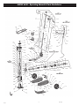
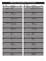
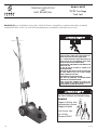
6635
s! WARNING
DO NOT OVERLOAD
AND.STOVERLOADING
THE ST
AND.
CAN CAUSE DAMAGE
AILURETO,
,OFOR
INSPECT EACH
F
ENSURE
AND
BOTH
STTO BE SURE IT
ANDS
ST ARE SET
T SAME
IS IN GOOD
A HEIGHT &
NO AL
TERA
USE ST
TIONS TO THE
ANDS INAIRS,
HOLDING DOGS
P ON HARD,
AND
ST SHALL BE MADE. CONDITION.
Y ENGAGED.
ARE FULL
PLACE LOAD IN
ACES
LOAD & ANDS
SURF
CAP
ABLE
ST SHALL ABLE. LEVEL
THE CENTER OF
AINING THE LOAD.
ST USE ON OTHER OF SUST
RESUL
THEY.SADDLE ONL
T IN POSSIBLE LOSSBE
USE SUPPOR
T POINTS SPECIFIED
THAN HARD,ACES
OF LOAD.
LEVELMA
READ, STUDY &
YSURF
DO NOT CRA
ACTURER.
MANUF
WL UNDER VEHICLE BY VEHICLE
UNDERST
AND THE INSTRUCTION
BEFORE USING
WHEN PLACING
AND.
ST
MANUAL
ACKED WITH
ORANDS.
REMOVING ST FAILURE
P
THIS
AND
ST
TO HEED THESE
ARNINGS
W YMA
AND/ORAILURE
RESUL
F
T IN LOSS OF LOAD,
RESUL
TING IN PROPER
DAMAGE
TY DAMAGE, PERSONAL
AND,TO ST
ATALOR
INJUR
F Y.
Use Service Jack
for Lifting
Purposes ONLY!
s! WARNING
Support Vehicle with
Appropriately Rated
Support Stands!
DO NOT OVERLOAD
AND.STOVERLOADING
THE ST
AND.
CAN CAUSE DAMAGE
AILURETO,
,OFOR
INSPECT EACH
F
ENSURE
AND
BOTH
STTO BE SURE IT
ANDS
ST ARE SET
T SAME
IS IN GOOD
A HEIGHT &
NO AL
TERA
USE ST
TIONS TO THE
ANDS INAIRS,
HOLDING DOGS
P ON HARD,
AND
ST SHALL BE MADE. CONDITION.
Y ENGAGED.
ARE FULL
PLACE LOAD IN
ACES
LOAD & ANDS
SURF
CAP
ABLE
ST SHALL ABLE. LEVEL
THE CENTER OF
AINING THE LOAD.
ST USE ON OTHER OF SUST
RESUL
THEY.SADDLE ONL
T IN POSSIBLE LOSSBE
USE SUPPOR
T POINTS SPECIFIED
THAN HARD,ACES
OF LOAD.
LEVELMA
READ, STUDY &
YSURF
DO NOT CRA
ACTURER.
MANUF
WL UNDER VEHICLE BY VEHICLE
UNDERST
AND THE INSTRUCTION
BEFORE USING
WHEN PLACING
AND.
ST
MANUAL
ACKED WITH
ORANDS.
REMOVING ST FAILURE
P
THIS
AND
ST
TO HEED THESE
ARNINGS
W YMA
AND/ORAILURE
RESUL
F
T IN LOSS OF LOAD,
RESUL
TING IN PROPER
DAMAGE
TY DAMAGE, PERSONAL
AND,TO ST
ATALOR
INJUR
F Y.
OPERATING INSTRUCTIONS
AND
PARTS BREAKDOWN
Model # 6635
22/35 Two Stage
Truck Jack
Model 6635 is an air/hydraulic service jack in which the lift arm is actuated by a mechanism that utilizes a relatively
incompressible fluid, such as oil, as the force transmitting means, actuated by a pneumatic power source.
USE ONLY ON HARD LEVEL SURFACES.
DO NOT GET UNDER A VEHICLE THAT IS ONLY SUPPORTED BY A
TROLLEY/SERVICE JACK–USE VEHICLE SUPPORT STANDS.
THIS IS A LIFTING DEVICE ONLY. DO NOT MOVE OR DOLLY THE
VEHICLE WHILE ON THE JACK. IMMEDIATELY AFTER LIFTING,
SUPPORT THE VEHICLE WITH APPROPRIATE MEANS.
DO NOT OVERLOAD. OVERLOADING CAN CAUSE DAMAGE TO OR
FAILURE OF THE JACK.
LIFT ONLY ON AREAS OF THE VEHICLE AS SPECIFIED BY THE
VEHICLE MANUFACTURER.
CENTER LOAD ON SADDLE PRIOR TO LIFTING. OFF-CENTER LOADS
MAY CAUSE DAMAGE TO JACK, LOSS OF LOAD, PROPERTY
DAMAGE, PERSONAL OR FATAL INJURY.
NO ALTERATIONS TO THE JACK SHALL BE MADE.
READ, STUDY AND UNDERSTAND THE OPERATING MANUAL
PACKED WITH THIS JACK BEFORE OPERATING.
FAILURE TO HEED THESE WARNINGS MAY RESULT IN LOSS
OF LOAD, DAMAGE TO JACK, AND/OR FAILURE RESULTING IN
PROPERTY DAMAGE, PERSONAL OR FATAL INJURY.
For Your Safety & to Prevent Injury:
ALWAYS
CAPACITY
RATCHETING
JACK STAND
Model 1003
3 TON
CAPACITY
RATCHETING
JACK STAND
Model 1003
3 TON
09/15/06
MODEL 6635 - Operating Manual & Parts Breakdown
6635 SPECIFICATIONS
FEATURES
•
•
Capacity 1st Ram . . . . . . . . . . . 35 Tons
Capacity 2nd Ram . . . . . . . . . . 22 Tons
•
•
•
•
Min. Saddle Height . . . . . . . . . . . 7 7/8"
Max. Saddle Height . . . . . . . . . 14 3/8"
Power Lift . . . . . . . . . . . . . . . . . . 6-1/2"
Chrome Plated Lift Ram
Self-Retracting Ram Springs for
Fast Ram Retraction
Push Valve Lever for Fast Air Control
3 Position Lock Lever
Safety Overload Valve
Large Diameter Wheels for Ease of Operation
Handle Length. . . . . . . . . . . . 42 11/16"
OWNER/USER RESPONSIBILITY
INSPECTION
Visual inspection should be made before each use
of the service jack, checking for leaking hydraulic
fluid and damaged, loose or missing parts. Each
jack must be inspected by a manufacturer’s repair
facility immediately, if accidentally subjected to an
abnormal load or shock. Any jack which appears
to be damaged in any way, found to be badly
worn, or operates abnormally MUST BE REMOVED
FROM SERVICE until necessary repairs are made
by a manufacturer’s authorized repair facility.
It is recommended that an annual inspection of
the jack be made by a manufacturer’s authorized
repair facility and that any defective parts, decals
or warning labels be replaced with manufacturer’s
specified parts.
A list of authorized repair facilities is available
from the manufacturer.
The owner and/or user must have a thorough
understanding of the manufacturer’s operating
instructions and warnings before using this service
jack. Personnel involved in the use and operation of
equipment shall be careful, competent, trained, and
qualified in the safe operation of the equipment and
its proper use when servicing motor vehicles and their
components. Warning information should be
emphasized and understood. If the operator is not fluent
in English, the manufacturer’s instructions and warnings
shall be read to and discussed with the operator in the
operator’s native language by the purchaser/owner,
making sure that the operator comprehends its contents.
Owner and/or user must study and maintain for future
reference the manufacturer’s instructions. Owner and/or
user is responsible for keeping all warning labels and
instruction manuals legible and intact.
Replacement labels and literature are available from the
manufacturer.
6635
2
09/15/06
MODEL 6635 - Operating Manual & Parts Breakdown
OPERATING INSTRUCTIONS
IMPORTANT: Before attempting to raise a vehicle,
check vehicle service manual for recommended
lifting surfaces.
1. To raise load: Close release valve tightly (by
turning handle knob clockwise). DO NOT
OVERTIGHTEN. Position jack under load so
that saddle will contact load firmly and load is
centered so it cannot slip. Operate the air
valve until saddle approaches the load. Once
again check to see that saddle is correctly positioned. Raise load to desired height. Place jack
stands of appropriate capacity under the vehicle.
DO NOT CRAWL UNDER VEHICLE WHILE
LIFTING VEHICLE OR PLACING OR REMOVING
JACK STANDS! Place jack stands at vehicle
manufacturer’s recommended lift areas that
provide stable support for the raised vehicle.
2. To lower load: Open release valve VERY SLOWLY
(by turning handle knob counterclockwise).
When release valve is opened, saddle and load
will be lowered. Lower the vehicle slowly so as
not to shock load the jack stands. Once repairs
are completed, raise vehicle enough to remove
jack stands. Lower vehicle very slowly.
CAUTION: Keep hands or feet away from the hinge
mechanism of the jack.
MAINTENANCE INSTRUCTIONS
IMPORTANT! Use only a good grade hydraulic jack
oil. Avoid mixing types of oil. Do not use brake fluid,
alcohol, glycerin, detergent motor oil, or dirty oil.
Improper fluid can cause serious internal damage to
the jack, rendering it inoperative.
To Add Oil: With saddle fully lowered and ram
depressed, set jack in an upright position and remove
oil filler plug. Fill until oil is just below filler plug hole.
To Change Oil: For best performance and longest life,
replace the entire oil supply at least once a year. To
drain the oil, remove the filler plug. Lay the jack on
its side and allow the oil to run out into suitable drain
pan. The oil will run slowly because air must enter as
oil drains out. Be careful to prevent dirt or foreign
matter from entering the system. Replace with
proper oil.
LUBRICATION
All moving joints require lubrication often. Remove
handle and grease the lower end of handle where it
connects to the release valve.
LIMITED WARRANTY:
SUNEX INTERNATIONAL, INC. WARRANTS TO ITS CUSTOMERS THAT THE COMPANY’S SUNEX TOOLS®
BRANDED PRODUCTS ARE FREE FROM DEFECTS IN WORKMANSHIP AND MATERIALS.
Sunex International, Inc. will repair or replace its Sunex Tools® branded products which fail to give satisfactory
service due to defective workmanship or materials, based upon the terms and conditions of the following described
warranty plans attributed to that specific product.
This product carries a ONE-YEAR warranty. During this warranty period, Sunex Tools will repair or replace at our
option any part or unit which proves to be defective in material or workmanship.
Other important warranty information...
This warranty does not cover damage to equipment or tools arising from alteration, abuse, misuse, damage and
does not cover any repairs or replacement made by anyone other than Sunex Tools or its authorized warranty
service centers.
The foregoing obligation is Sunex Tools’ sole liability under this or any implied warranty and under no
circumstances shall we be liable for any incidental or consequential damages.
Note: Some states do not allow the exclusion or limitation of incidental or consequential damages, so the above
limitation or exclusion may not apply to you.
Return equipment or parts to Sunex Tools, transportation prepaid. Be certain to include your name and address,
evidence of the purchase date, and description of the suspected defect.
If you have any questions about warranty service, please write to Sunex Tools. This warranty gives you specific legal
rights and you may also have other rights which vary from state to state.
Repair kits and replacement parts are available for many of Sunex Tools products regardless of whether or not the
product is still covered by a warranty plan.
Shipping Address: Sunex Tools • 315 Hawkins Rd. • Travelers Rest, SC 29690
Mailing Address: Sunex Tools • P.O. Box 4215 • Greenville, SC 29608
6635
3
09/15/06
MODEL 6635 - Operating Manual & Parts Breakdown
6635
4
09/15/06
MODEL 6635 - Operating Manual & Parts Breakdown
REF.
NO.
1.1
1.2
1.3
1.4
2.0
2.1
2.2
2.3
2.4
2.5
2.6
2.7
2.8
2.9
2.10
2.11
2.12
2.13
2.14
2.15
2.16
2.17
2.18
2.19
2.20
2.21
2.22
2.23
2.24
2.25
2.26
2.27
2.28
2.29
2.30
2.31
3.1
3.2
3.3
3.4
3.5
3.6
3.7
3.8
3.9
3.10
3.11
3.12
3.13
3.14
6635
PART
NO.
DESCRIPTION
Wheel Shaft
Wheel
Washer
Snap Ring
Piston Rod Assembly
through 2-26)
Cylinder
Spring Washer
Bolt
Nut
Machine Screw
*
Oil Strainer
*
Cylinder Bottom Seal
Oil Tank
Breathing Screw
*
O-Ring 3.15x1.8
RS6635211
Oil Plug Assembly
(includes 2-9, 2-10, 2-11, 2-12)
*
O-Ring 9.5x2.65
*
O-Ring 71x3.55
*
Seal Washer
Ram Header
*
Cylinder Bottom Seal
Retaining Ring
Cylinder
*
O-Ring 53x3.55
*
Seal Washer
Ram Header
Spring
Bush
Screw
Top Nut
*
O-Ring 53x3.55
*
O-Ring 140x5.3
Nut
*
O-Ring 69-5.3
Spring
RS6635231
Spring Hanger
*
O-Ring 11x1.9
Oil Box
*
Back-Up Ring
*
Steel Ball 6.5
*
Separator
*
Steel Ball 9.5
*
Spring
*
Copper Packing
Bolt
Bolt
*
Packing
*
Spring Retainer
*
Spring
*
Safety Valve
RS662213
RS662212
RS662214
RS663520
(includes 2-13
RS663521
REF.
NO.
QTY.
1
1
1
1
1
4.0
4.1
4.2
4.3
4.4
4.5
4.6
4.7
4.8
4.9
4.10
4.11
4.12
4.13
1
1
1
1
1
1
1
1
1
1
4.14
4.15
4.16
5.0
5.1
5.2
5.3
5.4.1
5.4.2
5.5.1
5.5.2
5.6
5.7
5.8
5.9.1
1
1
1
1
1
1
1
1
1
1
1
1
1
1
1
1
1
1
1
1
1
1
1
1
1
1
1
1
1
1
1
1
1
1
1
5.9.2
5.10
5.11
5.12
5.13
5.14
5.15
5.16
5.17
5.18
5.19
5.20
5.21
5.22
6.1
6.2
6.3
6.4
6.5
6.6
5
PART
NO.
RS663540
DESCRIPTION
QTY.
Release Valve Assembly
(includes 4-3, 4-4, 4-5, 4-6, 4-7)
Packing
*
O-Ring 15.6x2.65
Guide
Valve
*
O-Ring 14x2.4
*
Washer
Snap Ring
Universal Joint
Spring Pin
Spring Pin
Connectin Rod
Spring Pin
RS6635413
Universal Joint Assembly
(includes 4-8, 4-9, 4-10, 4-11, 4-12, 4-13)
Cotter Pin
Washer
Connecting Rod
RS663550
Handle Assembly
RS663551
Handle Fork
Spring Washer
Bolt
Connecting Rod
Connecting Rod
Up Handle
Lower Handle
Handle Cap
Spring Pin
RS662252
Knob
RS663559
Stopper
(includes 5-9-1, 5-9-2, 5-10, 5-11, 5-12)
Stopper
Spring Pin
Washer
Spring
Spring Pin
Machine Screw
Lock Lever
Lock Lever
Handle Cap
Spring Washer 6
Bolt M6x10
Retaining Ring
Hose Collect
Machine Screw
Frame
Lower Cover
Handle Fork Bracket
Spring Washer 10
Bolt M10x20
Bolt M6x12
1
1
1
1
1
1
1
1
1
1
1
1
1
1
1
1
1
1
1
1
1
1
1
1
1
1
1
1
1
1
1
1
1
1
1
1
1
1
1
1
1
1
1
1
1
1
1
1
1
09/15/06
MODEL 6635 - Operating Manual & Parts Breakdown
REF.
NO.
6.7
6.8
6.9
6.10
6.11
6.12
7.0
7.1
7.2
7.3
7.4
7.5
7.6
7.7
7.8
7.9
7.10
7.11
7.12
7.13
7.14
7.15
7.16
7.17
7.18
7.19
7.20
7.21
7.22
7.23
7.24
7.25
7.26
7.27
7.28
7.29
7.30
7.31
7.32
7.33
10.0
10.1
10.2
10.3
10.4
10.5
10.6
10.7
10.8
10.9
10.10
10.11
10.12
10.13
6635
PART
NO.
RS6635610
RS663570
*
RS663574
*
*
*
*
*
*
*
*
*
*
*
*
RS66221030
RS66221015
DESCRIPTION
Spring Washer
Bolt M12x20
Spring Washer 12
Upper Cover
Lock Washer
Machine Screw
Air Pump Assembly
Packing
Thread Seal
Cover
Pump Plunger Cover
Adjusting Nut
Cover
"Y" Seal
NL Retainer
Packing Guide
Nut
Spring
Plunger
Block
Nut MS
O-Ring 63.5x3.55
Square Ring
Piston
Seal
O-Ring
Air Pump Body
Cover
Spring Washer
Hex Socket Screw
Washer
O-Ring
Removeable Base
Spiral Clamp
Shuttle Valve
O-Ring
O-Ring
Spinge
Muffler
Bolt
Air Valve Assembly
Pump Elbow
Hose Band
Air Hose
Spring
Hose Band
Hose Connector
Valve Body
Spring
Throttle
O-Ring 3x1.6
Packing
O-Ring 18x2.4
Nut
QTY.
1
1
1
1
1
1
1
1
1
1
1
1
1
1
1
1
1
1
1
1
1
1
1
1
1
1
1
1
1
1
1
1
1
1
1
1
1
1
1
1
1
1
1
1
1
1
1
1
1
1
1
1
1
1
REF.
NO.
10.14
10.15
10.16
10.17
10.18
10.19
10.20
10.21
12.1
12.2
12.3
12.4
12.5
12.6
12.7
12.8
12.9
PART
NO.
RS6622121
RS6622122
RS6622123
RS6622124
RS6622125
+
+
+
RS6622129
DESCRIPTION
Lock Lever
Lever Pin
Lever
Connector
O-Ring
Air Filter
Connecting Nut
Connector
Adaptor-A
Adaptor-B
Adaptor-C
Adaptor-D
Holder Adaptor
U-Bolt
Spring Washer
Nut
Hitch Pin
QTY.
1
1
1
1
1
1
1
1
1
1
1
1
2
4
4
3
Note: Only items identified by part
number are available individually.
Asterisked items are only in the repair kit, RS6635SK.
Items marked + are available in bolt
kit, RS6622BK
09/15906
6635
6
09/15/06