1
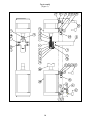
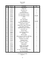
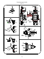
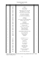
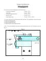
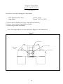
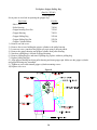
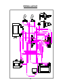
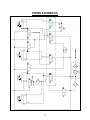
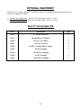
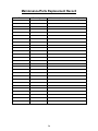
Tension-Air® Operating and Service Manual TA-3D Automatic Hose Clamping Machine Model No. Serial No. Owner: Owner Address: Date Purchased: P.O. Number: Optional Equipment: Air Lubricator: 3/8" Clamp Holder: 3/8" Punch/Cutter: 3001 N. 4th Street Enid, OK 73701 Ph. (888) 3062405 FAX (580) 2331353 Table of Contents SAFETY INSTRUCTIONS 3 SAFETY SYMBOLS 3 SPECIFICATIONS 4 UNPACKING AND SETTING UP 5 INCOMING AIR SUPPLY 5 OPERATING INSTRUCTION 6 MAINTENANCE AND LUBRICATION 7 AIR FILTERING AND LUBRICATION 8 TROUBLE CHECK LIST 8 BILL OF MATERIAL & PARTS LIST 9 Top Assembly Puller Housing Assembly Frame Assembly Pneumatic Control Assembly 10 12 13 14 PARTS REPLACEMENT 16 INSTRUCTIONS FOR CHANGING PARTS 17 To Replace Punch To Replace Punch Holder/Cutter To Replace Clamp Holder To Replace Gripper Pulling Dog To Replace Sensor 17 18 19 20 21 PIPING LAYOUT 22 PIPING SCHEMATIC 23 OPTIONAL EQUIPMENT 24 LIMITED WARRANTY 25 MAINTENANCE/PARTS REPLACEMENT RECORD 26 2 SAFETY INSTRUCTIONS READ THIS MANUAL THOROUGHLY Safety symbols are intended to attract your attention to possible danger. If you don't understand any portion of this manual, contact Punch-Lok or your authorized Punch-Lok representative, before operating machine. SAFETY SYMBOLS ► Safety Warning! Failure to obey a safety warning may result in injury to you or to others. ▪ Note: Advises you of instructions or information vital to the operation and maintenance of your TA3D. As with most machines, the TA-3D Tension Air Machine has many moving components. Wherever possible, moving parts have been covered. However, by necessity some parts are exposed to the operator. The operator, or any observer, is cautioned to keep all bodily extremities away from moving components while the machine is in operation. IT IS IMPORTANT TO: 1) Familiarize yourself with operating controls. 2) Never allow untrained personnel to operate this machine. 3) Wear proper attire. Do not dress in loose fitting clothing that may become caught in a moving part of the machine. 4) Never place fingers or hands between pistons, punch holder/cutter, backup cylinder, or any of their supporting surfaces, whether such components are in motion or at rest, so long as the air feed line is connected to the unit. 5) Always disconnect the air line from the unit when the machine is not in use, or an operator is not present. 6) Do not operate the machine with any covers removed. If maintenance or troubleshooting is required which necessitates removing any covered surfaces, first disconnect the air line. Immediately replace all covers when maintenance has been completed. 3 SPECIFICATIONS The model TA-3D fully automatic hose clamping machine is designed for use with Punch-Lok punch type hose clamps. Clamps are manufactured in 3/8" and 5/8" widths, using stainless steel or high carbon galvanized steel. It may be used to couple hoses up to a maximum outside diameter of 6-1/4 inches. To prevent attack by moisture or corrosive elements, most components have been plated or painted. ▪ Note: If other styles or other manufacturer's brands of center punch clamps are used, it may damage the clamping machine or result in the clamp not being properly installed on the hose which could cause the hose to come off the fitting. ▪ Note: The TA-3D is equipped with a manual drain filter, which needs periodic cleaning. See specifications "Air Filtering & Lubrication" on page 7. The following chart shows overall dimensions and requirements for the TA-3D: Chart 1 Height (to work surface) Height (overall) Weight (shipping) Weight (un-crated) Width Depth Air Requirement Machine Air Adjustments Air Filter Standard Clamp Use 32" (Less skid) 39" 290 lbs. 245 lbs. 18" 36" 100 PSI @ 3CFM See "Incoming Air Supply," Pg. 5 Manual Drain 5/8" or (3/8" optional) The TA-3D operates in a 3-stage cycle, with a slight time delay between each function. Once the machine is properly adjusted for a given application, each hose clamp will be identically tensioned and locked in place. For more details see page 6 entitled "Operating Instructions." Since the TA-3D is pneumatically operated, an air source is required. While air compressors are available in various sizes, types and styles, the requirements (see Chart 1) to keep the TA-3D operating satisfactorily must be maintained. If your plant contains other equipment requiring the use of air, consideration must be given to such requirements. Storage must be sufficient to operate all such equipment so that the TA-3D will not be starved for air. ▪ Note: If there are irregularities in air flow a low pressure malfunction may occur. 4 UNPACKING AND SETTING UP The TA-3D is shipped on wooden skids so as to prevent damage in shipment. The skids do not need to be removed! The skids permit ease of mobility should the machine need to be relocated. Locate the TA3D on a flat, level surface. After receiving the machine, thoroughly inspect it for visible damage. If damage is evident, do not attempt to proceed to connect or use the machine. Immediately contact the carrier and place a claim. Failure to do so may relieve the carrier from responsibility. If no physical damage is evident, proceed to determine a suitable location where the TA-3D will be used. A work table placed to the right or left of the machine will prove valuable in the event that long lengths of hose need to be coupled. INCOMING AIR SUPPLY ► Safety Warning! Cylinders may move when the air supply is hooked up to the TA-3D machine. Keep all extremities away from moving components. As noted in the "Specifications" section of this manual, your available air supply for use with the TA-3D must be 100 PSI. Incoming air pressure should be regulated between 90-95 PSI. This adjustment has been pre set at the factory. A second regulator is used on the tension cylinder. The tension cylinder regulator should be set between 50-75 PSI (50-65 PSI for 3/8" clamps). The exact pressure will be determined by trial and error depending on the construction type of hose being coupled. In order to set the tension cylinder regulator, depress palm button and hold. Let the machine cycle. While still holding palm button in, adjust regulator with opposite hand. Upon releasing the palm button, the gauge on the tension cylinder regulator should then return to 0 PSI. Another regulator is used to adjust the force exerted by the back-up cylinder. Normal operating pressure should be 50-65 PSI. This pressure may be set as low as 20 PSI if the higher pressure is breaking or crushing the fittings. The higher the pressure setting will result in better installed clamps. The back-up cylinder regulator is adjusted in the same manner as the tension cylinder regulator. After adjustments have been made, run the machine through one complete cycle to verify proper regulator settings. If the pressure readings are not correct, repeat the above procedures. ▪ Note: If incoming air pressure falls below 50 PSI, the TA-3D will not function properly. 5 The air pressure settings indicated are for all Punch-Lok clamp diameters up to 6-1/4". Variations in material used in clamp manufacturing, variation from your main air source, the construction type of hose, and the type of fitting to be coupled, all may contribute to slight changes being needed to one or both of the regulators. Slight adjustments to the regulator may be required due to the following: 1) 2) 3) 4) Variations in steel used for clamp manufacturing Air pressure variation in building Construction type of hose to be coupled Type of fitting being coupled ► Safety Warning! If any adjustments are to be made on either regulator, keep hands and bodily parts away from any moving components. OPERATING INSTRUCTION The TA-3D has been designed to operate in a cycling sequence for the safety of the operator, and to safeguard components of the machine from damage. The cycle sequence is: A) Grip tail piece and tension clamp. B) Back-up block moves into position and holds clamp. C) Punch/holder cutter moves forward to punch the clamp. D) Punching and cutting operations completed. The TA-3D has (3) pneumatic sensors which control the operations of the above sequence. Cycle A is started by depressing the Palm Button. Cycles B, C, and D are initiated at the proper times by the sensors mentioned. ► Safety Warning!! Always wear protective glasses while operating. Hose Coupling Adjust the tension cylinder regulator and the back-up cylinder regulator to the proper settings as describe in Incoming Air Supply on page 5. To couple hose, first select the proper size clamp for the hose diameter being coupled. Place the proper amount of clamps on the end of the hose and install the fitting in the hose. Insert the clamp tail of the clamp closest to the end of the fitting into the clamp adapter slot, with the lok facing the punch. ▪ Note: Push the clamp all the way down until the base of the lok bottoms against the support block! Failure to do so may cause the gripper to not grip the clamp! 6 With one hand steadying the hose and the other hand on the palm button, depress the palm button. This button is located on the front side of the machine beneath the back-up cylinder. This starts the coupling cycle. ► Safety Warning! It is important to keep one hand on the palm button and your other hand on the hose being coupled. Keep your hand on the hose far away from the clamp being assembled, and far from all other moving components. ▪ Note: The operator must keep the palm button depressed through the complete coupling cycle. If the cycle is interrupted by the release of the palm button prior to the final punching of the clamp lok, it will be necessary to recycle the machine. An exception to this is if an oversized clamp is being used, the button can be released before the back-up cylinder extends so that another grip can be made on the clamp. Repeat the procedure until all clamps have been installed. MAINTENANCE AND LUBRICATION ► Safety Warning! Never attempt to perform any maintenance function, nor lubrication, to this machine without first disconnecting the air source. Very little maintenance is required to keep the TA-3D operating properly. However, the following maintenance should be performed periodically. Place a few drops of light machine oil between operating surfaces of all moving parts, especially between punch/cutter holder and support block. Periodically clean the unit (particularly at the area around the clamp holder and inside the opening of the puller housing by the gripper dog) Use a blow gun to remove chips, galvanizing material and any other dirt and debris. ► Safety Warning! Always wear protective glasses. Collect and clean out clamp tail pieces which have been discharged at the base of the unit. A pan has been provided inside the frame to collect and more readily remove tail pieces. 7 AIR FILTERING AND LUBRICATION Keep incoming air from your compressor filtered at all times. Keep the air filter clean and drained of collected water. This machine is equipped with a model BO8 Manual Drain, Filter/Regulator. To maintain maximum filtering efficiency and to avoid excessive pressure drops, the filter must be kept clean at all times. A visible coating of dirt on the filter element, or an excessive pressure drop is an indication that cleaning is necessary. To clean the filter, disconnect the air line from the machine and de-pressurize filter. Remove the filter (no tools required) and clean with household soap. TROUBLE CHECK LIST Your TA-3D should give you trouble free performance if you check the following components and items carefully, before operating: 1) 2) 3) 4) 5) 6) 7) 8) 9) 10) 11) 12) 13) Filter is clean and drained of water Machine connected to air source 100 PSI available from compressor All regulators properly set Clamp holder is free of chips and debris Punch is sharp Proper diameter clamp is used Proper width clamp used Moving components lubricated with machine oil All machine covers are in place Clamp tail pieces have been removed Machine is on flat, level surface Operator has been trained to operate machine If: 1-Machine will not operate: A- Check item 1,2, and 3 above B- Check for jammed tail pieces in puller housing C- Check for water or moisture in air lines D- Faulty palm button or sensor 2-Improper clamp tension A- Insufficient incoming air B- Tension regulator set too low C- Worn or dirty gripper (see #9 following) D- Clamp diameter too large for hose (see #8 following) 8 E- Check for galvanizing material caught in gripper 3-Punch not deep enough A- Main regulator set too low B- Back-up regulator set too low C- Worn punch 4-Clamp cutter not cutting A- Insufficient incoming air B- Regulator set too low C- Worn cutter D- Worn or damaged clamp holder 5-Sluggish operation A- Insufficient incoming air B- Regulator set too low C- Dirty air filter or water in air lines (see #10 following) 6-Punch off center of "Lok" A- Clamp "lok" not bottomed in clamp holder, i.e. gripper not holding tail piece 7-Tail piece caught in gripper A- Press palm button for one or two seconds and disengage 8-Clamp too large for hose A- Press palm button to activate gripper and tension cylinder. When clamp tail stops pulling take hand off palm button to let machine reset, then press palm button again to pull clamp tight or repeat as necessary until clamp is tight. 9-Gripper slips off clamp tail A- To determine if gripper is worn, first use blow gun to clean gripper and clean any debris from puller housing, then retry. 10-Water in system A- Turn drain screw on filter counter clockwise. Allow excess water to drain, then re-tighten nut. BILL OF MATERIAL & PARTS LIST All component parts for the TA-3D are shown in the following section. The machine has been subdivided into 4 groups. Shown in each group is a numbered parts drawing, and the corresponding Bill of Material. Each Bill of Material lists the part #, assembly #, description, and the quantity required. The 4 groups are as follows: Top Assembly (Fig. 1) Puller Housing Assembly (Fig. 2) Frame Assembly (Fig. 3) Pneumatic Controls (Fig. 4) 9 Top Assembly (Figure 1) 10 Top Assembly (Figure 1) Item Part No. Description Qty. 1 2 3 755552 753209 753208 Support Block Guide Plate Flat Head Screw 1 2 4 4 5 755510 753213 Guide Block Guide Block Allen Bolt 1 4 6 755553 5/8" Punch Holder & Cutter 1 6 7 755554 252020 3/8" Punch Holder & Cutter Punch Optional 1 8 252030 Set Screw 1 9 9 755557 755551 5/8" Clamp Holder 3/8" Clamp Holder 1 Optional 10 755526 Clamp Holder Flat Head Screw 2 11 12 755556 755527 Clamp Holder Support Clamp Holder Support Allen Bolt 1 2 13 755529 Support Block Allen Bolt 4 14 15 755530 755532 Support Block Spacer Allen Bolt Punch Pin Cotter 4 1 16 755555 Punch Linkage 1 17 18 755502 755531 Punch Linkage Jam Nut Punch Pin 1 1 19 755521 Punch Cylinder 1 20 21 753222 755519 Elbow Connector 3/8 NPT x 3/8 Tubing Bushing 3/4 NPT x 3/8 NPT 4 4 22 753201 Pneumatic Sensor Body 3 23 24 753202 755517 Pneumatic Sensor Punch Cylinder Spacer 3 2 25 755533 Backup Cylinder 1 26 27 755514 755525 Backup Block Cylinder Mounting Bolt 1 8 28 755528 Support Block Spacer 2 29 755516 3/8” Plug-In Nipple 1 30 755518 3/8” One-Touch x 3/8” FNPT Elbow 1 31 755030 Flow Control Muffler 1 Puller Housing Assembly (Figure 2) 11 Item 1 2 3 4 5 6 7 8 9 10 11 12 13 14 15 16 17 18 Part No. 754501 754502 754520 754505 754506 252140 252120 754521 753263 754507 754514 754509 754510 753201 753202 753222 755030 754512 Description Puller Housing Gripper Cylinder Gripper Cylinder Pusher Gripper Cylinder Mtg. Bolt Elbow Connector, 1/8 NPT x 1/4 Tubing Pulling Dog Pulling Dog Pin Gripper Housing Gripper Housing Pin Set Screw Tension Cylinder Jam Nut Bushing 1/2 NPT X 3/8 NPT Pneumatic Sensor Body Pneumatic Sensor Elbow Connector 3/8 NPT x 3/8 Tubing Flow Control Muffler Cylinder Mounting Bolt Frame Assembly (Figure 3) 12 Qty. 1 1 1 4 2 1 2 1 1 1 1 1 2 1 1 1 1 4 Item Part No. Description Qty. 1 754030 Frame 1 2 754033 Side Cover 2 3 754004 Metal Screw 12 4 754013 Back-up Cylinder Nameplate 1 5 754006 Tension (Pull-Up) Cylinder Nameplate 1 13 Pneumatic Control Assembly (Figure 4) 14 Pneumatic Control Assembly (Figure 4) Item Part No. Description Qty. 1 755054 4-Way Valve 4 2 755034 Muffler 4 3 753315 3/8” One-Touch Tee 2 4 755516 3/8” Plug-In Nipple 2 5 755001 Straight Connector 1/4"NPT x 3/8" Tubing 1 6 755043 Tube End Reducer 3/8" x 1/4" Tubing 2 7 753313 Elbow Connector 1/4"NPT x 3/8" Tubing 5 8 755520 3/8” One-Touch x 3/8” Plug In Elbow 1 9 753222 3/8” One-Touch x 3/8” NPT Elbow 3 10 755041 3/8” One-Touch x 1/4” NPT Male Run Tee 1 11 753335 1/4” Brass Tee 1 12 753333 1/4” Hex Nipple 1 13 755522 5/32” One-Touch x 1/8” NPT Double Branch Elbow 1 14 753336 Bushing 1/4" MNPT x 1/8" FNPT 1 15 755523 3/8” Plug Insert 1 16 753306 Filter/Regulator 1 17 755048 Filter/Regulator Mounting Bracket 1 18 755006 Street Elbow 3/8"NPT 1 19 755046 5/32” One-Touch x 1/8” NPT Elbow 4 20 753332 Back-Up Cylinder Regulator 1 21 755014 Regulator Mounting Nut 2 22 755045 2” Pressure Gauge W/Bracket 2 23 755053 Straight Connector 1/8" FNPT x 5/32" Tubing 2 24 753332 Tension Cylinder Regulator 1 25 755014 Regulator Mounting Nut 1 26 *755015 Palm Button Body 1 27 *755016 Palm Button 1 29 755019 Hex Head Bolt 1/4"-20- x 1/2" 4 30 755037 8 x 32 x 2 1/4 Allen Head 4 31 755035 Hex Nut 8 x 32 4 32 755021 Hex Nut 1/4"-20 4 33 755055 4-Way Manifold Base 1 34 753328 .156 OD Tubing 7 35 753334 Filter Regulator Gauge 1 36 755026 Male Quick Disconnect 1 37 756577 Ambient Dryer 1 38 756578 Ambient Dryer Mounting Bracket 1 39 755032 Supply Port Interface 1 40 755031 4-Way Valve (Complete) Ref #1 #33 #39 1 28 *When replacing these parts on older units, discard the existing Palm Button Bezel (Part No. 755017) to improve mounting clearance. 15 PARTS REPLACEMENT Three component parts of the TA-3D will need to be periodically replaced, frequency dependent upon the machine use and the type of hose clamp material used. These three parts are: Punch - Part # 252020 Clamp Holder - Part # 755557 (5/8") or # 755551 (3/8") Pulling Dog - Part # 252140 Punch Holder/Cutter – Part # 755553 (5/8”) or # 755554 (3/8”) The use of stainless steel hose clamps will wear (dull) these parts more rapidly than with the use of coldrolled steel clamps. The listing below identifies these three parts by "Drawing Assembly" number. Also listed are other components which, may need to be replaced if damaged in use, or where necessary to change over to a different type component: i.e. change from the use of 5/8" wide clamps to 3/8" clamps wide clamps. Assembly 23 7 6 6 9 9 Top Assembly (Figure 1) Part Name Pneumatic sensor Punch 5/8" Punch holder/cutter Part No. 753202 252020 755553 3/8" Punch holder/cutter 5/8" Clamp holder 3/8" Clamp holder 755554 755557 755551 Puller Housing Assembly (Figure 2) Assembly 15 6 Part Name Pneumatic sensor Pulling dog 16 Part No. 753202 252140 INSTRUCTIONS FOR CHANGING PARTS ►Safety Warning: Before attempting to replace any part, the air line must be disconnected from the TA3D. To Replace Punch (Part No. 252020) (See Figure 5) Four parts are involved in replacing the punch. Punch Part No. 252020 Guide Block Part No. 755510 Punch Set Screw Part No. 252030 Guide Block Allen Bolt 1) 2) 3) 4) 5) 6) Part No. 753213 Unscrew the 4 guide block allen bolts. Remove the guide block. The punch holder will now be exposed. Remove the single set screw from the top of punch holder/cutter. Replace worn punch. (A 3/32" hole is provided in case the punch is stuck.) Tighten set screw. Replace all parts in their original position. Figure 5 17 To Replace Punch Holder/Cutter (Part No. 755553 or 755554) (See Figure 6) Five parts are involved in changing the punch holder/cutter: Guide Block Allen Bolts Part No. 753213 Guide Block Part No. 755510 Linkage Pin (Punch Drift Pin) Part No. 755531 Hair Pin Cotter Part No. 755532 Punch Holder/Cutter Part No. 755553 or 755554 1) 2) 3) 4) 5) Unscrew, and remove, the allen bolts from the guide block. The punch holder will now be exposed. Remove the hair pin cotter. Remove the punch drift pin. Replace punch holder/cutter. Replace all parts in their original position. ▪ Note: A new punch should be used when replacing punch holder/cutter. See "To Replace Punch" on Page 17. Figure 6 18 To Replace Clamp Holder (Part No. 755557 or 755551) (See Figure 7) Two parts are involved in changing the Clamp Holder: Clamp Holder Flat Head Screw Clamp Holder Part No. 755526 Part No. 755557 or 755551 1) Unscrew the two flat-head cap screws, using an allen wrench key. 2) Remove worn or broken clamp holder and replace. 3) Reverse the procedure for assembly. ▪ Note: The clamp holder is two sided, and may be flipped over for continued use. Figure 7 GUIDE BLOCK CLAMP HOLDER CLAMP HOLDER SCREWS SUPPORT BLOCK 19 To Replace Gripper Pulling Dog (Part No. 252140) (See Figure 8) Seven parts are involved in replacing the gripper dog: Part Name Part No. Side Cover 754033 Puller Housing 754501 Gripper housing Pivot Pin 753263 Gripper Housing 754521 Gripper Pulling Dog 252140 Gripper Pulling Dog Pin 252120 Gripper Cylinder Pusher 754520 1) Remove one side cover. 2) Remove four screws holding the gripper cylinder to the puller housing. 3) Loosen set screw: punch out the gripper pivot pin using a drift pin punch. 4) Remove the gripper housing and gripper cylinder from puller housing. 5) Note how pulling dog is located on gripper housing. 6) Remove pulling dog pin, and remove pulling dog; replace with new pulling dog. 7) Replace pulling dog pin 8) Align gripper housing back into puller housing and insert gripper pin. Make sure the gripper cylinder and gripper housing stay assembled. 9) Tighten set screw and reinstall gripper cylinder mounting screws. 10) Replace side cover. Figure 8 20 To Replace Sensor (Part No. 753202) (See Figure 9) ▪ Note: Sensors are located on the cylinder ports. 1. The sensor assembly is comprised of two basic components: The body and the sensor. Most generally the sensor will be the part that will usually go bad. 2. Disconnect main air supply to machine. 3. Disconnect both air lines leading into the sensor. ▪ Note: Make sure the lines are identified as to which one leads into the sensor and which one leads out. 4. See arrows on sensor. 5. Remove the metal spring clip from the sensor/body. 6. Pull sensor out of the body and replace. 7. Reassemble in reverse order of disassembly. Figure 9 SENSOR RRR SENSOR BODY WIRE CLIP 21 PIPING LAYOUT 22 PIPING SCHEMATIC 23 OPTIONAL EQUIPMENT To make the TA-3D more functional, should the need arise, the following optional equipment may be ordered and adapted in the field. 1) Alternate 3/8" clamp holder – Used for 3/8" wide clamps. Part No. 755551 2) Alternate 3/8" punch/cutter - Must be used with number 1. Part No. 755554 TA-3 8” Conversion Kit Part # Description Qty. 755512 8” Tie Rod Extension 1 755513 Backup Block/ 8” Machine 1 756590 3/8 x 16 x 2-1/2 SHCS 4 756591 3/4-10 x 2-3/4 SHCS 4 756592 3/8 FPT x 3/8 MPT SHCS Adapter 1 756593 3/8 NPT Coupling 3 756594 3/8 NPT Hex Coupling 3 756595 1/8 NPT Coupling 2 756596 1/8 NPT Hex Coupling 2 24 LIMITED WARRANTY Punch-Lok Company warrants each new TA-3D Tension Air Machine for one (1) year according to the following terms: This warranty extends to the original purchaser only and commences from the original date of shipment. Any part of the TA-3D manufactured by Punch-Lok Company and found in the reasonable judgment of Punch-Lok Company to be defective in material or workmanship, will be repaired or replaced without charge for parts or labor, but without obligation to pay the cost of transportation of the machine, if returned to the factory, or back to the purchaser, nor any transportation costs of replacement parts. This Warranty does not cover any TA-3D that has been subject to misuse, negligence, accident, alteration or modification. The warranty is voided if the TA-3D is not operated and maintained in accordance with the instructions contained in this manual, or if the machine is used for any purpose for which it was not designed. Air cylinders, controls valves, regulators, sensors or other components not designed nor manufactured by Punch-Lok Company are not covered under this warranty, but are subject to the warranty of the respective manufacturer of such components. This warranty does not extend to repairs made necessary by normal wear. Due to varying material characteristics this warranty remains effective only if the TA-3D is used to couple hoses with genuine Punch-Lok punch type hose clamps. Punch-Lok Company reserves the right to make design and manufacturing changes without responsibility to modify any machine previously manufactured. The implied warranty of merchantability is hereby expressly disclaimed. There are no warranties which extend beyond the description on the face hereof. 25 Maintenance/Parts Replacement Record Date Hours Oper. Maintenance, Lubrication, Parts Replaced 26