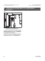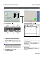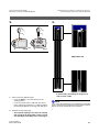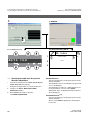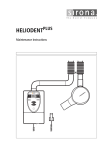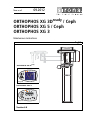
1
MVKOMNO
kÉï=~ë=çÑW=
loqelmelp=ud=PaêÉ~Çó=L=`ÉéÜ
loqelmelp=ud=R=L=`ÉéÜ
loqelmelp=ud=P
j~áåíÉå~åÅÉ=fåëíêìÅíáçåë=====
båÖäáëÜ
ORTHOPHOS XG 3Dready
Easypad
ORTHOPHOS XG 5 / 3
P1
Prog.
T
R
Multipad
sÉêëáçå=SKM
S
kV
mA
Sirona Dental Systems GmbH
Maintenance Instructions ORTHOPHOS XG
General information
ATTENTION !
Proper shielding of room and operator
position is essential.
Since these requirements vary from state
to state it is the assembler's/installer's
responsibility that all local radiation
safety requirements are met.
kÉï=~ë=çÑW=
MVKOMNO
Changes since the last version: 12.2010
Chapter or section
page
1 General ...................................................................... 5
5 Tube Current Verification .......................................... 10
6 kV – verification / Exposure Time Verification .......... 13
2
59 38 373 D3352
D3352.103.01.06.02
Sirona Dental Systems GmbH
Maintenance Instructions ORTHOPHOS XG
Contents
1
General ................................................................................................................................ 5
2
Visual Check ....................................................................................................................... 6
3
Indicator Lights and audible Signal.................................................................................. 7
4
Power supply adequacy..................................................................................................... 9
5
Tube Current Verification ................................................................................................ 10
6
kV – verification / Exposure Time Verification............................................................... 13
7
Checking the X-Ray Beam ............................................................................................... 15
7.1
8
Diaphragm/system adjustment menu ..................................................... 15
Checking the X-Ray Beam for panorama exposure ...................................................... 17
8.1
8.2
8.3
8.4
8.5
9
kV – verification ...................................................................................... 14
Exposure Time Verification..................................................................... 14
båÖäáëÜ
6.1
6.2
Preparing the Pan adjustment ................................................................
Checking the pan sensor adjustment .....................................................
Checking the pan diaphragm adjustment ...............................................
Checking the pan filter adjustment .........................................................
Checking the pan symmetry ...................................................................
17
18
20
22
24
Checking the X-Ray Beam for cephalometer exposure................................................ 26
9.1
9.2
9.3
9.4
Preparing the Ceph adjustment ..............................................................
Checking the Ceph primary diaphragm adjustment................................
Checking the ceph rotation fixpoint adjustment ......................................
Checking the ceph main X-ray beam direction adjustment ....................
26
27
30
32
10 Checking the alignment of the ear plugs ....................................................................... 34
10.1
10.2
Preparing the ear olives.......................................................................... 34
Checking the ear plug alignment ............................................................ 35
11 Checking the laser............................................................................................................ 38
59 38 373 D3352
D3352.103.01.06.02
3
Sirona Dental Systems GmbH
Maintenance Instructions ORTHOPHOS XG
4
59 38 373 D3352
D3352.103.01.06.02
Sirona Dental Systems GmbH
Maintenance Instructions ORTHOPHOS XG
General
To stay in compliance with the DHHS requirements the
ORTHOPHOS XG must be maintained annually following
date of installation.
It is the responsibility of the user to insure that the equipment is maintained with the manufacturer's recommended
Maintenance Instructions to insure compliance with the
Federal Performance Standard.
The manufacturer and the assembler/installer are relieved
from responsibility in those cases where noncompliance
with the standard results from the user's failure to have the
manufacturer's recommended maintenance performed.
The actual maintenance inspection and consequent service must be accomplished by a trained serviceman. Neither the inspection nor service is part of the equipment warranty.
Technical instructions required
Operating Instructions
Service Manual
Instruments and adjustment tools required
All measuring devices must be suitable for measurements
on the mains potential.
This includes the pulse counter.
This means: A voltage of 1000 V between a connection and
ground must be possible.
1.
Digital multimeter Fluke 87 III or equivalent.
Accuracy:
DC voltage ± 0.1 % of reading plus 0.02% of range
DC current ± 0.4 % of reading plus 0.1% of range.
ATTENTION
RADIATION!
Observe the radiation protection guide lines as outlined in
the Operating Instructions manual.
X-radiation is emitted as long as the release button is depressed.
The X-ray indicator must light up on the Easypad during radiation. An acoustic signal must also be heard.
Power Supply Adequacy
To assure that the ORTHOPHOS XG system performance
is in accordance with Sirona specifications, an adequate
power supply for permanently installation is essential.
The Federal Performance Standard for diagnostic X-ray
units, code of Federal Regulations, Title 21 CFR, Subchapter J, mandates an adequate power supply.
Duty Cycle
Between exposures maintain at least a cool-off time (automatic exposure blockage, see Operating Instructions manual).
Operating Instructions
During measurements and controls it is necessary to energize or de-energize the unit. For all operating steps please
refer to the Operating Instructions manual.
CAUTION with PC Boards!
All PC boards are fitted with electronic components sensitive to electrostatic discharge (ESD). In an environment of
moving people electrostatic charges are unavoidable due to
friction caused by clothing, carpeting etc.
ATTENTION
2.
A dose measurement device (e.g. Mult-O-Meter
type 510L) is required for dosimetry
To prevent damage of electronic chips do not touch same.
Always handle circuit boards by their edges.
ATTENTION
3.
Adjustment set with alignment tool for X-ray beam , test
block and needle phantom delivered with the unit, (customer's property).
Electrical Shock Hazard!
Always turn unit OFF before connecting and disconnecting
the test leads to the test points
ON
OFF
WARNING
Life-threatening voltage on DX6.
59 38 373 D3352
D3352.103.01.06.02
5
båÖäáëÜ
1
1 General
2 Visual Check
2
Sirona Dental Systems GmbH
Maintenance Instructions ORTHOPHOS XG
Visual Check
SIDEXIS
Software
Logiciel
•
•
•
•
Look for mechanical damage possibly affecting radiation safety.
Verify that all labels are affixed and legible.
Defaced labels must be replaced.
Order same from Sirona (address, see rear)
in writing stating:
Customer Name
Customer Address
All Model Numbers with Serial Numbers still legible on the
unit for identification purposes. For serial numbers see also
Installation Report/Warranty Passport.
6
59 38 373 D3352
D3352.103.01.06.02
Sirona Dental Systems GmbH
Maintenance Instructions ORTHOPHOS XG
3
3 Indicator Lights and audible Signal
Indicator Lights and audible Signal
Radiation indicator
Unit ON LED
XG 3Dready
ON
OFF
Unit ON LED
båÖäáëÜ
Radiation indicator
Remote
P1
Prog.
T
S
kV
mA
XG 5 / 3
R
•
Unit ON LED:
Depress the main switch into the ”I” position to turn unit
ON.
The unit adjusts itself automatically, wait about
1 minute.
The ”Unit ON LED” in the upper right corner of the user
interface will then indicate that the unit is ON.
•
Testing the keys and the functions on the user interface.
– When the height adjustment is made the loudspeaker should hum.
– If the forehead support functions correctly, the max.
holding torque is still present.
– If remote is installed, test the remote keys and display in addition.
– The release button must not be defective or broken.
See also Operating Instructions under
”Preparing the Exposure” subchapter
”Switching the system on”.
59 38 373 D3352
D3352.103.01.06.02
7
3 Indicator Lights and audible Signal
Sirona Dental Systems GmbH
Maintenance Instructions ORTHOPHOS XG
CAUTION RADIATION !
Observe Radiation Protection Guide Lines
see Operating Instructions
Radiation indicator
Unit ON LED
Radiation indicator
Unit ON LED
menu
keys
P1
Prog.
T
S
kV
mA
submenukeys
R
Return key R
Return key R
Make a exposure:
– X-ray head must be in the initial position (If not,
press return key R).
– Establish exposure readiness via SIDEXIS.
For more details and possible error messages see
Operating Instructions.
– Set the P1 exposure program using the menu keys
(XG 5 / 3) or – + keys (XG 3Dready).
– Select 68kV/8mA using submenu keys (XG 5 / 3)
or submenu – + keys (XG 3Dready).
Submenu
ORTHOPHOS XG 3D ready
ORTHOPHOS XG 5 / 3
•
– + keys
•
Interrupt an exposure – deadman feature:
– Observe a cool-off time of max. 5 mins. between
exposures (automatic exposure blockage).
– Setting same as above.
CAUTION RADIATION
–
Depress the release button until X-ray lights up and
subsequently release – the exposure must
terminate immediately. The radiation indicator
lights up.
ATTENTION
CAUTION RADIATION
–
–
–
–
8
Depress the exposure button and hold until the
exposure terminates automatically.
The exposure ends when the rotation and radiation
automatically switch off.
The radiation indication must light up during the
exposure period.
Simultaneously an audible beep must sound at the
unit.
Defective light indicators constitute a safety hazard to the
patient as well as to the operator.
The user is not permitted to use the unit, until repairs
are made!
59 38 373 D3352
D3352.103.01.06.02
Sirona Dental Systems GmbH
Maintenance Instructions ORTHOPHOS XG
4
4 Power supply adequacy
Power supply adequacy
1.
2.
300 VAC
3.
båÖäáëÜ
K1
➊
*o
*o
4. - 5.
K1
•
To determine power supply adequacy, the line voltage drop during exposure must be measured.
Line voltage, no load:
Max. permissible line voltage
drop:
1.
Be sure power is disconnected at the central distribution panel!
Remove front cover (for details see Service Manual).
180 – 208V
9V
208 – 230V
8V
230 – 240V
7.5V
240 – 264V
7V
•
2.
3.
Select 300VAC line voltage range on multimeter .
Connect measuring leads to terminal K1, L and N.
Connect power and switch unit ON ➊ .
Wait 1 min. for self-adjustment of the unit.
Press key R o to return X-ray tube head into the initial
position.
4.
Establish exposure readiness via SIDEXIS.
5.
Select highest exposure level e.g. 90kV/12mA.
–
Depress the exposure key until meter reading is
obtained.
CAUTION RADIATION
59 38 373 D3352
D3352.103.01.06.02
Record reading.
•
Turn unit OFF.
•
Remove meter leads and refit cover.
i
NOTE
If the voltage drop is not within the specified range advise the customer, that an adequate power supply must be
installed. Refer to Pre-Installation Instructions.
Disconnect unit and do not release for use!
9
5 Tube Current Verification
5
Sirona Dental Systems GmbH
Maintenance Instructions ORTHOPHOS XG
Tube Current Verification
1.
2.
A
B
WARNING
The electronics of the X-ray tube assembly are always
connected to line voltage.
Always switch the X-ray unit off and wait until V203 is
no longer illuminated before contacting the test leads.
1.
Remove cover (for details see Service Manual).
2.
Loosen the four screws A and remove cover plate B of
the electronics box.
WARNING
The test leads and measuring instruments used must
have a dielectric strength of at least 1000V!
Be sure to use a battery-powered measuring instrument with shock-hazard-protected sockets.
Use only test leads with shock protection.
ATTENTION
The X-ray tube assembly moves during the measurement.
Therefore, be sure to use test leads of sufficient length and
place the measuring instrument in a location where it is firmly seated so that it doesn’t fall down.
10
59 38 373 D3352
D3352.103.01.06.02
Sirona Dental Systems GmbH
Maintenance Instructions ORTHOPHOS XG
3.
5 Tube Current Verification
4.
20mADC
D
C
MA+
båÖäáëÜ
com.
MA–
5.
400 VDC
4. - 5.
➊
A
*
PC-board DX6
o
WARNING
Be sure to switch the X-ray unit off before removing the
jumper for the mA measuring jack.
3.
Remove jumper A from MA+/MA – test points on PC
board DX6. Connect digital ammeter to MA+ and MA–
and select range 20 mADC.
4.
Reattach cover C and tighten screw D securely.
5.
Switch unit ON ➊ .
Wait 1 min. for self-adjustment of the unit.
Press key R o to return X-ray tube head into the initial
position.
6.
Select 66kV/8mA. Establish exposure readiness via
SIDEXIS.
7.
If P1 program and 66kV/8mA are selected .
The unit must be ready for radiation.
59 38 373 D3352
D3352.103.01.06.02
XG 3Dready
*
o
XG 5 / 3
Measurement:
CAUTION RADIATION
–
Depress the exposure key and hold depressed until
meter reading is obtained.
The ammeter shall indicate 8mA ±1.6mA.
Record reading.
i
NOTE
Readings: 1mA corresponds to a tube current of 1mA, permissible tolerance +/-20%.
i
NOTE
If specified values cannot be obtained, see Service Manual, chapter ”Tube Current Verification”.
11
5 Tube Current Verification
Sirona Dental Systems GmbH
Maintenance Instructions ORTHOPHOS XG
8.
9.
•
If specified value is obtained switch unit OFF.
8.
•
Remove upper cover and meter leads
Replace jumper!
9.
Screw the cover plate back on to the electronics box.
10.
10. Reattach the housing covers.
12
59 38 373 D3352
D3352.103.01.06.02
Sirona Dental Systems GmbH
Maintenance Instructions ORTHOPHOS XG
6
6 kV – verification / Exposure Time Verification
kV – verification / Exposure Time Verification
1.
4.
A
A
B
A
-
60kV/8mA
+
S2
-
0.5s
+
3
C
R
båÖäáëÜ
T
7.
Preparing the measurement
1.
Attach the Mult-O-Meter sensor in the middle of the dual sensor.
2.
Switch the unit on via the switch A (see also Operating
Instructions)
ª The X-Ray radiation indicator (B) lights up briefly.
ª After approx. 2 seconds, the green LED (C) in the
upper part of the control panel lights up. This LED
remains lit as long as the unit is on.
ª The start screen appears on the touchscreen of
the Easypad and the system's self-adjustment
routine starts running (for approx. 1 minute). The
rotating element rotates briefly clockwise and
counterclockwise. The diaphragm moves into
position. The forehead and temple supports on the
panoramic unit open and close and then stop
moving in fully opened position.
4.
Call the Service menu and the Service routine S002.3
(see Service Manual).
5.
Use the arrow keys (A) in selection field 1 to select the
kV/mA level 62kV/8mA.
6.
Use the arrow keys (A) in selection field 2 to select the
radiation time 0.5 s.
Performing measurements
7.
Initiate the radiation. Hold the release button pressed
until the set radiation time has expired.
CAUTION! Activating the release button triggers
X-rays
ª On completion of the self-adjustment routine, the
main menu appears on the touchscreen. Help
message H301 prompts you to move the unit into
the starting position.
3.
Press the R key.
ª The unit moves to its starting position.
59 38 373 D3352
D3352.103.01.06.02
13
6 kV – verification / Exposure Time Verification
6.1 kV – verification
Sirona Dental Systems GmbH
Maintenance Instructions ORTHOPHOS XG
kV – verification / Exposure Time Verification
6.1 kV – verification
Analyzing measurements
➢ Read the voltage values on the Mult-O-Meter.
ª
The value for the voltage displayed on the
Mult-O-Meter must correspond to the 62 kV
selected in the service routine. The permissible
tolerance is ± 10 %..
ª
If the measured values do not fall within the
permissible tolerance range, replace the tube
assembly (see Service Manual).
ª
If the measured values fall within the permissible
tolerance range, finalize the measurement.
6.2 Exposure Time Verification
Analyzing measurements
➢ Read the radiation time on the Mult-O-Meter.
ª
The value for the radiation time displayed on the
Mult-O-Meter must correspond to the radiation
time of 0.5s selected in the service routine. The
permissible tolerance is ± 10 %.
ª
If the measured radiation time does not fall within
the permissible tolerance, replace the tube
assembly (see Service Manual).
ª
If the measured radiation time falls within the
permissible tolerance, finalize the measurement.
Finalizing the measurement
➢ Exit the service routine.
➢ Switch off the unit (see Operating Instructions).
14
59 38 373 D3352
D3352.103.01.06.02
Sirona Dental Systems GmbH
Maintenance Instructions ORTHOPHOS XG
7
7 Checking the X-Ray Beam
7.1 Diaphragm/system adjustment menu
Checking the X-Ray Beam
2.
XG 3Dready
båÖäáëÜ
1.
3.
XG 5
SERVICE
7.1 Diaphragm/system adjustment menu
The DIAPHRAGM/SYSTEM ADJUSTMENT menu guides
you through the adjustment of the panoramic unit and the
cephalometer. This service routine is started from SIDEXIS
XG:
EXTRAS Æ CONSTANCY TEST Æ XCXP Æ SELECT X-RAY
DEVICE Æ SERVICE EXPOSURE Æ DIAPHRAGM/SYSTEM
ADJUSTMENT
i
NOTE
The DIAPHRAGM/SYSTEM ADJUSTMENT menu is password-protected. As password, enter the first four digits of
the current system date (PC) in reverse order.
ORTHOPHOS XG 3Dready / Ceph:
This mode is indicated by the PC service screen (2.) displayed on the Easypad. In PC service mode, the Easypad
control options are determined by SIDEXIS and the currently selected service routine. General control of the unit by
means of the Easypad (as in the user mode) is not possible
in this mode.
ORTHOPHOS XG 5 / Ceph, ORTHOPHOS XG 3 .
This mode is indicated by the message SERVICE (3.) on
the Multipad. In PC service mode, the Multipad control options are determined by SIDEXIS and the currently selected
service routine. General control of the unit by means of the
Multipad (as in the user mode) is not possible in this mode.
Example: On 05/30/2004, the service password is 5003
i
NOTE
When you open the DIAPHRAGM/SYSTEM ADJUSTMENT
menu, the unit switches from the user mode to the PC service mode logged by the PC.
59 38 373 D3352
D3352.103.01.06.02
15
7 Checking the X-Ray Beam
7.1 Diaphragm/system adjustment menu
Sirona Dental Systems GmbH
Maintenance Instructions ORTHOPHOS XG
The DIAPHRAGM/SYSTEM ADJUSTMENT menu has
11 submenus:
z
Pan - Sensor adjustment
z
Pan - Diaphragm
z
Pan - Filter
z
Pan - Symmetry
z
Ceph - Primary diaphragm
z
Ceph - Fixed point of rotation
z
Ceph - Main X-ray beam direction
z
Ceph -Quickshot (full version only)
z
Pan - Reset adjustment
z
Ceph - Reset adjustment
z
Sirona Service Sheet (internal SIRONA information)
You can change between the individual submenus by clicking the tabs with the mouse. To quit the DIAPHRAGM/
SYSTEM ADJUSTMENT menu, click CANCEL.
16
59 38 373 D3352
D3352.103.01.06.02
Sirona Dental Systems GmbH
Maintenance Instructions ORTHOPHOS XG
8
8 Checking the X-Ray Beam for panorama exposure
8.1 Preparing the Pan adjustment
Checking the X-Ray Beam for panorama exposure
1.
2.
Needles on
top side
båÖäáëÜ
A
8.1 Preparing the Pan adjustment
In order to perform the PAN sensor adjustment and the
symmetry adjustment you must insert needle phantom A
in the bite block holder of the panoramic X-ray unit.
The needle phantom must be removed from the bite block
holder for the pan diaphragm adjustment.
ATTENTION
It is essential that the needle phantom is removed from bite
block holder of the panoramic X-ray unit again before a
Ceph exposure is taken; otherwise the phantom may collide
with the sensor.
i
NOTE
When fitting the needle phantom, make sure that it is
correctly oriented. For the adjustment of the X-ray unit, the
phantom must be fitted in such a way that the needles
point upward (2.).
59 38 373 D3352
D3352.103.01.06.02
17
8 Checking the X-Ray Beam for panorama exposure
8.2 Checking the pan sensor adjustment
Sirona Dental Systems GmbH
Maintenance Instructions ORTHOPHOS XG
1.
in SIDEXIS
2.
on the touchscreen (XG 3Dready)
on the Multipad (XG 5 / 3)
E
1
60/3
0.60
-
X RAY
60 kV/3 mA
0.6 s
2
+
S10
1
3
?
8.2 Checking the pan sensor adjustment
•
Plug the sensor into the sensor slot on the panoramic
X-ray unit.
•
Insert the needle phantom in the bite block holder of the
panoramic X-ray unit (see page 17).
1.
Open the PAN
i
- SENSOR ADJUSTMENT submenu.
NOTE
The menu provides a precision adjustment and a coarse adjustment (precision adjustment is preset). Perform a precision adjustment first. In most cases, previous coarse adjustment is not necessary.
2.
18
Make SIDEXIS XG ready for exposure:
Click IMAGE ACQUISITION.
ORTHOPHOS XG 5 / 3:
The exposure dialog box showing the exposure status
appears in Sidexis.
The initialization status is visualized by a progress indicator on the Multipad.
The initialization procedure is completed when the exposure parameters of service routine S010.1
(60 kV/3 mA; 0.6 s) are displayed and the progress indicator disappears.
ORTHOPHOS XG 3Dready:
The exposure dialog box showing the exposure status
appears in Sidexis.
Service routine S010.1 is displayed on the Easypad
touchscreen.
59 38 373 D3352
D3352.103.01.06.02
Sirona Dental Systems GmbH
Maintenance Instructions ORTHOPHOS XG
8 Checking the X-Ray Beam for panorama exposure
8.2 Checking the pan sensor adjustment
4.
3.
Prog.
R
G
XG 3Dready
mA
R
G
T
kV
båÖäáëÜ
T
S
XG 5 / 3
Adjustment: ok
i
3.
Take an exposure (60 kV/3 mA):
– Press the R key to move the unit back to the
starting position.
NOTE
If the criteria specified above are not fulfilled, the sensor
must be adjusted. The procedure for adjusting the unit is described in the service manual.
– Press the release button. Hold down the release
button until image acquisition is completed and the
preview image appears in the exposure dialog box.
4.
Evaluate the exposed image:
– The three needle images must lie in the center
of the exposed areas and inside the auxiliary
lines (see image 4.).
59 38 373 D3352
D3352.103.01.06.02
19
8 Checking the X-Ray Beam for panorama exposure
8.3 Checking the pan diaphragm adjustment
Sirona Dental Systems GmbH
Maintenance Instructions ORTHOPHOS XG
ready
XG 3D
/ Ceph,
1. ORTHOPHOS
ORTHOPHOS XG 5 / Ceph
in SIDEXIS
2.
on the touchscreen (XG 3Dready)
on the Multipad (XG 5)
E
1
60/3
0.20
2
-
X RAY
60 kV/3 mA
0.20 s
+
S30
2
3
?
8.3 Checking the pan diaphragm
adjustment
•
Remove the needle phantom from the bite block holder
of the panoramic X-ray unit.
1.
Change to the PAN
i
- DIAPHRAGM submenu.
NOTE
For XG 3Dready, XG 5
The menu provides a precision adjustment and a
coarse adjustment. Always try to use precision adjustment first when adjusting the unit. In most cases, it is
not necessary to perform a coarse adjustment prior to
precision adjustment.
2.
20
Make SIDEXIS XG ready for exposure:
Click IMAGE ACQUISITION.
ORTHOPHOS XG 5 / 3:
The exposure dialog box showing the exposure status
appears in Sidexis.
The initialization status is visualized by a progress indicator on the Multipad.
The initialization procedure is completed when the exposure parameters of service routine S030.2
(60 kV/3 mA; 0.6 s) are displayed and the progress indicator disappears.
ORTHOPHOS XG 3Dready:
The exposure dialog box showing the exposure status
appears in Sidexis.
Service routine S030.2 is displayed on the Easypad
touchscreen.
59 38 373 D3352
D3352.103.01.06.02
Sirona Dental Systems GmbH
Maintenance Instructions ORTHOPHOS XG
8 Checking the X-Ray Beam for panorama exposure
8.3 Checking the pan diaphragm adjustment
3.
4.
Prog.
R
G
XG 3Dready
mA
R
G
T
kV
båÖäáëÜ
T
S
XG 5 / 3
Adjustment: ok
3.
Take an exposure (60 kV/3 mA):
– Press the R key to move the unit back to the
starting position.
– Press the release button. Hold down the release
button until image acquisition is completed and the
preview image appears in the exposure dialog box.
4.
sides must be visible. The maximum density
must lie in the center of the diaphragm area.
i
NOTE
If the current image differs from the ideal image (see image
4.), the diaphragm must be adjusted. The procedure for adjusting the unit is described in the service manual.
Evaluate the exposed image:
– The exposed diaphragm area must lie horizontally centered in the image field as well as
inside the superimposed auxiliary lines.
– A white border surrounding the image on all
59 38 373 D3352
D3352.103.01.06.02
21
8 Checking the X-Ray Beam for panorama exposure
8.4 Checking the pan filter adjustment
Sirona Dental Systems GmbH
Maintenance Instructions ORTHOPHOS XG
1.
in SIDEXIS
2.
on the touchscreen (XG 3Dready)
on the Multipad (XG 5)
E
1
60/3
0.20
2
-
X RAY
60 kV/3 mA
0.20 s
+
S30
3
3
?
8.4 Checking the pan filter adjustment
Not necessary for ORTHOPHOS XG 3
- FILTER submenu.
1.
Change to the PAN
2.
Make SIDEXIS XG ready for exposure:
Click IMAGE ACQUISITION.
ORTHOPHOS XG 3Dready:
The exposure dialog box showing the exposure status
appears in Sidexis.
Service routine S030.3 is displayed on the Easypad
touchscreen.
ORTHOPHOS XG 5:
The exposure dialog box showing the exposure status
appears in Sidexis.
The initialization status is visualized by a progress indicator on the Multipad.
The initialization procedure is completed when the exposure parameters of service routine S030.3
(60 kV/3 mA; 0.6 s) are displayed and the progress indicator disappears.
22
59 38 373 D3352
D3352.103.01.06.02
Sirona Dental Systems GmbH
Maintenance Instructions ORTHOPHOS XG
8 Checking the X-Ray Beam for panorama exposure
8.4 Checking the pan filter adjustment
4.
3.
Prog.
R
G
XG 3Dready
mA
R
G
T
kV
båÖäáëÜ
T
S
XG 5
Adjustment: ok
i
3.
Take an exposure (60 kV/3 mA):
– Press the R key to move the unit back to the
starting position.
NOTE
If the current image differs from the ideal image (see image
4.), the diaphragm must be adjusted. The procedure for adjusting the unit is described in the service manual.
– Press the release button. Hold down the release
button until image acquisition is completed and the
preview image appears in the exposure dialog box.
4.
Evaluate the exposed image:
– The superimposed filter must cover one half of
the diaphragm (see image 4.).
59 38 373 D3352
D3352.103.01.06.02
23
8 Checking the X-Ray Beam for panorama exposure
8.5 Checking the pan symmetry
Sirona Dental Systems GmbH
Maintenance Instructions ORTHOPHOS XG
1.
in SIDEXIS
2.
on the touchscreen (XG 3Dready)
on the Multipad (XG 5 / 3)
E
1
60/3
14.1
2
-
X RAY
60 kV/3 mA
14.1 s
+
S10
2
3
?
8.5 Checking the pan symmetry
•
Insert the needle phantom in the bite block holder of the
panoramic X-ray unit (see page 17).
1.
Change to the PAN
2.
Make SIDEXIS XG ready for exposure:
Click IMAGE ACQUISITION.
- SYMMETRY submenu.
ORTHOPHOS XG 5 / 3:
The exposure dialog box showing the exposure status
appears in Sidexis.
The initialization status is visualized by a progress indicator on the Multipad.
The initialization procedure is completed when the exposure parameters of service routine S010.2
(60 kV/3 mA; 0.6 s) are displayed and the progress indicator disappears.
ORTHOPHOS XG 3Dready:
The exposure dialog box showing the exposure status
appears in Sidexis.
Service routine S010.2 is displayed on the Easypad
touchscreen.
24
59 38 373 D3352
D3352.103.01.06.02
Sirona Dental Systems GmbH
Maintenance Instructions ORTHOPHOS XG
8 Checking the X-Ray Beam for panorama exposure
8.5 Checking the pan symmetry
3.
Prog.
R
G
XG 3Dready
mA
R
G
T
kV
båÖäáëÜ
T
S
XG 5 / 3
4.
ZOOM: 1:1
± 0.75 mm
± 0.75 mm
A1 = 88.6 mm ± 1 mm
A2 = 44.3 ± 0.5 mm
A2
A2
A2 = 44.3 ± 0.5 mm
Adjustment: ok
3.
Take an exposure (60 kV/3 mA):
- Distance A1 must be 88.6 ± 1 mm.
– Press the R key to move the unit back to the
starting position.
- Distances A2 must be identical, each being
44.3 ± 0.5 mm.
– Press the release button. Hold down the release
button until image acquisition is completed and the
preview image appears in the exposure dialog box.
4.
Evaluate the captured image.
- The shadow of the center needle, the needle image and the auxiliary line must be congruent and
located behind each other.
A tolerance (offset of needle from the central
auxiliary line) of ± 0.75 mm is admissible.
59 38 373 D3352
D3352.103.01.06.02
- A white border surrounding the image on all
sides must be visible (when zoomed out fully).
i
NOTE
If these criteria are not fulfilled, the symmetry must be adjusted. The procedure for adjusting the unit is described in
the service manual.
25
9 Checking the X-Ray Beam for cephalometer exposure
9.1 Preparing the Ceph adjustment
9
Sirona Dental Systems GmbH
Maintenance Instructions ORTHOPHOS XG
Checking the X-Ray Beam for cephalometer
exposure
1.
B
9.1 Preparing the Ceph adjustment
You must insert test phantom B in the sensor slot on the
panoramic X-ray unit in order to perform the adjustment
of the ceph primary diaphragm and the adjustment of
the ceph main X-ray beam direction.
The test phantom must be removed from the sensor slot on
the panoramic X-ray unit for the adjustment of the ceph
fixed point of rotation and for the ceph quickshot.
26
59 38 373 D3352
D3352.103.01.06.02
Sirona Dental Systems GmbH
Maintenance Instructions ORTHOPHOS XG
9 Checking the X-Ray Beam for cephalometer exposure
9.2 Checking the Ceph primary diaphragm adjustment
1.
in SIDEXIS
on the touchscreen (XG 3Dready)
on the Multipad (XG 5)
E
1
8 0 / 1 4 14 . 9
båÖäáëÜ
2.
-
X RAY
80 kV/14 mA
14.9 s
2
+
S10
3
3
?
9.2 Checking the Ceph primary diaphragm
adjustment
•
Move the ear plug holders on the cephalometer
completely apart and swing them out of the beam direction (ap).
•
Insert the test phantom in the sensor slot on the panoramic X-ray unit (see page 26).
•
Plug the sensor into the sensor slot on the cephalometer.
•
Open the DIAPHRAGM/SYSTEM ADJUSTMENT
menu.
- PRIMARY DIAPHRAGM submenu.
1.
Select the CEPH
2.
Make SIDEXIS XG ready for exposure:
Click IMAGE ACQUISITION.
59 38 373 D3352
D3352.103.01.06.02
ORTHOPHOS XG 5:
The exposure dialog box showing the exposure status
appears in Sidexis.
The initialization status is visualized by a progress indicator on the Multipad.
The initialization procedure is completed when the exposure parameters of service routine S010.3
(60 kV/3 mA; 0.6 s) are displayed and the progress indicator disappears.
ORTHOPHOS XG 3Dready:
The exposure dialog box showing the exposure status
appears in Sidexis.
Service routine S010.3 is displayed on the Easypad
touchscreen.
27
9 Checking the X-Ray Beam for cephalometer exposure
9.2 Checking the Ceph primary diaphragm adjustment
Sirona Dental Systems GmbH
Maintenance Instructions ORTHOPHOS XG
3.
Prog.
T
R
G
3.
XG 3Dready
kV
mA
R
G
T
S
XG 5
Take an exposure (80 kV/14 mA):
– Press the R key to move the unit back to the
starting position.
– Press the release button. Hold down the release
button until image acquisition is completed and the
preview image appears in the exposure dialog box.
28
59 38 373 D3352
D3352.103.01.06.02
Sirona Dental Systems GmbH
Maintenance Instructions ORTHOPHOS XG
9 Checking the X-Ray Beam for cephalometer exposure
9.2 Checking the Ceph primary diaphragm adjustment
båÖäáëÜ
4.
S2
S2
Adjustment: ok
S3 = approx. 60 mm
i
4.
NOTE
– The vertical pin must be horizontally centered
in the exposed image area.
If S3 is significantly larger than 60 mm, check whether light
barrier V61_1 (LB on the horizontal diaphragm slider) is
properly installed. If necessary, correct the alignment of the
light barrier and then repeat the entire pan and ceph adjustment procedure.
– A uniform white border surrounding the image
on all sides must be visible.
– Distance S3 must be approx. 60 mm.
i
V61_1
(must be installed
vertically)
Evaluate the captured image.
NOTE
A slight vertical offset of the grid is permissible.
i
NOTE
If the image differs from the ideal image 4., the ceph primary
diaphragm must be readjusted. The procedure for adjusting
the unit is described in the service manual.
59 38 373 D3352
D3352.103.01.06.02
29
9 Checking the X-Ray Beam for cephalometer exposure
9.3 Checking the ceph rotation fixpoint adjustment
Sirona Dental Systems GmbH
Maintenance Instructions ORTHOPHOS XG
1.
in SIDEXIS
2.
on the touchscreen (XG 3Dready)
on the Multipad (XG 5)
E
1
80/14
0.60
-
X RAY
80 kV/14 mA
0.60 s
2
+
S10
5
3
?
9.3 Checking the ceph rotation fixpoint
adjustment
•
Remove the ceph test phantom from the sensor slot of
the panoramic X-ray unit.
1.
Change to the CEPH
submenu.
i
- FIXED POINT OF ROTATION
NOTE
The menu provides a precision adjustment and a
coarse adjustment. Always try to use precision adjustment first when adjusting the unit. In most cases, it is
not necessary to perform a coarse adjustment prior to
precision adjustment.
2.
30
Make SIDEXIS XG ready for exposure:
Click IMAGE ACQUISITION.
ORTHOPHOS XG 5:
The exposure dialog box showing the exposure status
appears in Sidexis.
The initialization status is visualized by a progress indicator on the Multipad.
The initialization procedure is completed when the exposure parameters of service routine S010.5
(60 kV/3 mA; 0.6 s) are displayed and the progress indicator disappears.
ORTHOPHOS XG 3Dready:
The exposure dialog box showing the exposure status
appears in Sidexis.
Service routine S010.5 is displayed on the Easypad
touchscreen.
59 38 373 D3352
D3352.103.01.06.02
Sirona Dental Systems GmbH
Maintenance Instructions ORTHOPHOS XG
9 Checking the X-Ray Beam for cephalometer exposure
9.3 Checking the ceph rotation fixpoint adjustment
4.
3.
Prog.
R
G
XG 3Dready
mA
R
G
T
kV
båÖäáëÜ
T
S
XG 5
Adjustment: ok
3.
Take an exposure (80 kV/14 mA):
– Press the R key to move the unit back to the
starting position.
– Press the release button. Hold down the release
button until image acquisition is completed and the
preview image appears in the exposure dialog box.
4.
– A white border surrounding the image on all
sides must be visible.
i
NOTE
If the criteria specified above are not fulfilled, the ceph fixed
point of rotation must be adjusted. The procedure for adjusting the unit is described in the service manual.
Evaluate the exposed image:
– The exposed diaphragm area must lie centered
and straight in the image field as well as inside
the superimposed auxiliary lines (see image 4.).
59 38 373 D3352
D3352.103.01.06.02
31
9 Checking the X-Ray Beam for cephalometer exposure
9.4 Checking the ceph main X-ray beam direction adjustment
Sirona Dental Systems GmbH
Maintenance Instructions ORTHOPHOS XG
1.
in SIDEXIS
2.
on the touchscreen (XG 3Dready)
on the Multipad (XG 5)
E
1
80/14 14.9
-
X RAY
80 kV/14 mA
14.9 s
2
+
S10
6
3
?
9.4 Checking the ceph main X-ray beam
direction adjustment
•
Insert the test phantom in the sensor slot on the panoramic X-ray unit (see page 26).
•
Swing the ear plug holders out of the beam direction.
1.
Change to the CEPH - MAIN X-RAY BEAM
DIRECTION submenu.
2.
Make SIDEXIS XG ready for exposure:
Click IMAGE ACQUISITION.
ORTHOPHOS XG 5:
The exposure dialog box showing the exposure status
appears in Sidexis.
The initialization status is visualized by a progress indicator on the Multipad.
The initialization procedure is completed when the exposure parameters of service routine S010.6
(60 kV/3 mA; 0.6 s) are displayed and the progress indicator disappears.
ORTHOPHOS XG 3Dready:
The exposure dialog box showing the exposure status
appears in Sidexis.
Service routine S010.6 is displayed on the Easypad
touchscreen.
32
59 38 373 D3352
D3352.103.01.06.02
Sirona Dental Systems GmbH
Maintenance Instructions ORTHOPHOS XG
9 Checking the X-Ray Beam for cephalometer exposure
9.4 Checking the ceph main X-ray beam direction adjustment
3.
Prog.
R
G
XG 3Dready
mA
R
G
T
kV
båÖäáëÜ
T
S
XG 5
4.
10 mm
10 mm
10 mm
10 mm
Adjustment: ok
3.
Take an exposure (80 kV/14 mA):
4.
– Press the R key to move the unit back to the
starting position.
Evaluate the exposed image:
– A horizontal bar must be visible in the center of
the image (see image 4.). If this bar is visible,
the exposure is OK and ...
– Press the release button. Hold down the release
button until image acquisition is completed and the
preview image appears in the exposure dialog box.
– the two beams imaged are within the tolerance
band of ± 10 mm (see image 4.).
i
NOTE
If the criteria specified above are not fulfilled, the ceph main
X-ray beam direction must be adjusted. The procedure for
adjusting the unit is described in the service manual.
59 38 373 D3352
D3352.103.01.06.02
33
10 Checking the alignment of the ear plugs
10.1 Preparing the ear olives
Sirona Dental Systems GmbH
Maintenance Instructions ORTHOPHOS XG
10 Checking the alignment of the ear plugs
1.
2.
D
3.
10.1 Preparing the ear olives
i
NOTE
1.
Move the ear plug holders completely apart and swing
them into the beam direction.
2.
Fit adjusting caps D onto the ear plugs and secure them
with adhesive tape.
Black adjusting cap on the outside (sensor side),
Transparent adjusting cap on the inside (tube assembly side).
3.
Unscrew the cover from the cephalometer.
The sensor must be plugged into the sensor slot on the
cephalometer. No sensor may be plugged into the sensor
slot on the panoramic X-ray unit.
•
Select the CEPH mode on the Multipad (XG 5) or
Easypad (XG 3Dready).
34
59 38 373 D3352
D3352.103.01.06.02
Sirona Dental Systems GmbH
Maintenance Instructions ORTHOPHOS XG
1.
10 Checking the alignment of the ear plugs
10.2 Checking the ear plug alignment
2.
4.
båÖäáëÜ
3.
10.2 Checking the ear plug alignment
1.
In Sidexis XG, select the constancy test:
EXTRAS Æ CONSTANCY TEST
The typical SIDEXIS user interface is started. The constancy test is preset.
2.
Start the exposure mode:
Click XCXP
The dialog box for selecting the X-ray device appears
on the screen.
3.
Select/confirm the X-ray device:
Select e.g. Room2 (Kammer2) and click OK
The dialog box for selecting the test type appears on
the screen.
4.
Select/confirm the test type:
Click SERVICE EXPOSURE
The dialog box for selecting the service exposure appears on the screen.
59 38 373 D3352
D3352.103.01.06.02
35
10 Checking the alignment of the ear plugs
10.2 Checking the ear plug alignment
Sirona Dental Systems GmbH
Maintenance Instructions ORTHOPHOS XG
5.
i
NOTE
The ceph mode must be activated on the Multipad (XG 5) or
Easypad (XG 3Dready) for the ceph quality test exposure.
5.
i
Select/confirm the service exposure:
Click QUALITY TEST EXPOSURE.
NOTE
If necessary, select the X-ray component.
The exposure dialog box showing the exposure status
appears in Sidexis.
36
59 38 373 D3352
D3352.103.01.06.02
Sirona Dental Systems GmbH
Maintenance Instructions ORTHOPHOS XG
10 Checking the alignment of the ear plugs
10.2 Checking the ear plug alignment
6.
Prog.
R
G
6.
mA
R
G
T
XG 3Dready
kV
båÖäáëÜ
T
S
XG 5
Take an exposure (80 kV/14 mA):
– Press the R key to move the unit back to the
starting position.
– Press the release button. Hold down the release
button until image acquisition is completed and the
preview image appears in the exposure dialog box.
•
The lead balls in the adjusting caps appear as dots
on the image. The two dots must be coincident.
i
NOTE
If the criteria specified above is not fulfilled, the ear olives
must be adjusted. The procedure for adjusting the ear olives
is described in the service manual.
59 38 373 D3352
D3352.103.01.06.02
37
11 Checking the laser
10.2 Checking the ear plug alignment
Sirona Dental Systems GmbH
Maintenance Instructions ORTHOPHOS XG
11 Checking the laser
1.
Horizontal beam
Vertical beam
2.
C
A
B
Label
1.
Insert the forehead and temple supports.
2.
Check the laser:
•
Fasten a piece of white cardboard between the temple
supports.
•
Swivel the mirror by pressing the left recess A on the
touch bar.
•
Switch on the light localizer with key B on the Easypad/Multipad. The Lasers generate a red line.
WARNING
Class 1 radiation is emitted during installation.
Always keep eyes a minimum distance of 100mm
away from the laser. Do not stare into the beam.
38
SAG laser (vertical line)
The light beam must strike the center of the head support
in a vertical direction.
FH laser (horizontal line)
The light beam must strike the FH line of the sheet of cardboard attached to the head support. It must be possible to
displace the light beam vertically using slide C. Unwanted
movement of the FH light localizer is not permitted.
i
NOTE
To adjust the lasers, see Maintenance Instructions.
No controls are available to adjust the laser power.
59 38 373 D3352
D3352.103.01.06.02
loqelmelp=ud
Yearly Maintenance Checklist
Customer: _________________________ Address:_________________________
Dealer:____________________________ Address:_________________________
Date of original installation: ___________ Date of inspection: ________________
Report of Assembly FD 2579 # _________
____________________________________
_______
Yes
SCHEDULE
Remarks
No
All manuals are present
Test instruments as required
Manufacturer
Model
Accuracy
Last calibrated
Voltmeter
mAmeter
Dosimeter
Any mechanical damage noticed
All labels are present and legible
All indicator lights are OK
Radiation indicator X-ray lights up, audible buzzer OK
Deadman feature OK
Line voltage: . . . . . . . . . .V
Voltage drop: . . . . . . . . . V
Power supply adequate
kV – Verification is OK
Tube current is within specified limits
Measurement: . . . . . . . mA
Specified exposure time OK
Measurement: . . . . . . . . .
X-ray beam position, panoramic OK
X-ray beam position, ceph OK
The unit is in compliance with MFG specified tests and safety
Technician:
D3352.103.01.06.02
Dealer:
59 38 373 D3352
tÉ=êÉëÉêîÉ=íÜÉ=êáÖÜí=íç=ã~âÉ=~åó=~äíÉê~íáçåë=ïÜáÅÜ=ã~ó=ÄÉ=êÉèìáêÉÇ=ÇìÉ=íç=íÉÅÜåáÅ~ä=áãéêçîÉãÉåíëK
=
aPPROKNMPKMNKMSKMO===MVKOMNO
péê~ÅÜÉW=ÉåÖäáëÅÜ=
ûKJkêKW= NNS=PUO
mêáåíÉÇ=áå=dÉêã~åó
fãéêáã¨=Éå=^ääÉã~ÖåÉ
páêçå~=aÉåí~ä=póëíÉãë=dãÄe
áå=íÜÉ=rp^W
c~Äêáâëíê~≈É=PN
SQSOR=_ÉåëÜÉáã
dÉêã~åó
ïïïKëáêçå~KÅçã
páêçå~=aÉåí~ä=póëíÉãë=ii`
QUPR=páêçå~=aêáîÉI=pìáíÉ=NMM
`Ü~êäçííÉI=k`=OUOTP
rp^
lêÇÉê=kç
RV=PU=PTP=aPPRO