1
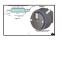
Installation
Manual
Operators
Manual
TM
excellence
AA3200, AA240, & AA400 Series Dry Air Pumps
TM
Aero Accessories, Inc.
1240 Springwood Avenue, Gibsonville, NC 27249 USA
FAA-PMA Approved
TORNADO
000
3
TAKING AVIATION BY STORM
Tornado AA3215CC, AA3215CC-9, and the AA3216CW Series Dry Air Pumps
as well as our AA240 and AA400 Series Dry Air Pumps are truely
revolutionary. They incorporate proven technology, designed to provide
long service life and reduce premature failures.
2
TM
Aero Accessories, Inc. ‘Tempest’ AA3200 Series, AA240 Series, & AA400 Series Dry Air pumps incorporate our
patented “channel cut” in the mounting flange face, which when utilized with our patented LRT Diverter, is
designed to channel oil away from mechanical workings of the pump, if the drive pad’s oil seal begins to leak.
The Closed Front End is designed to elimate oil and or / solvent residues from entering the pump’s drive
mechanism.
3
TM
Most dry air pumps are installed with the inlet and outlet ports in the 12:00, 3:00, 6:00, or 9:00 positions.
Tornado pumps have four (4) exit channels in the mounting flange face. When a pump is installed on an
aircraft the three (3) upper-most channels MUST be plugged by the LRT diverter. The bottom channel is left
open to allow oil to drain away from the pump’s mechanical workings. In other words, the open, unplugged
channel should be pointing towards the ground.
The photographs below and on the next page illustrate proper installation positions of the LRT diverter when
the pump ports are at different positions.
Ports at 12:00 Position
LRT on TOP
LRT Diverter
Installed
Ports at 9:00 Position
(from pilot’s view)
LRT on TOP
Channel Pointing
towards bottom
(ground)
Leave Open
4
TM
The photographs below show the inlet and outlet ports at the 6:00 and 3:00 positions. Notice that in both pictures
the bottom channel is open and pointing towards the ground. The LRT diverter MUST be installed so that the lower
drain channel of the mounting flange remains open and pointing towards the ground.
NOTE:
On Cessna 150 / Continental O-200 and some other engines the pump mounts with the drive shaft vertical. Pumps
designed for vertical installation such as the AA3215CC-9, AA215CC-9, or AA211CC-9 are normally required. When
installing an AA3215CC-9 the open channel should face aft towards the firewall and away from sources of oil contamination. On Cessna 172’s having 2 pumps on the engine, the lower pump mounts with the ports slightly rotated at
about 20 degrees. The channel pointing closest to the ground should be left open.
Ports at 6:00 Position
LRT on TOP
LRT Diverter
Installed
Ports at 3:00 Position
(from pilots view)
LRT on TOP
Leave Channel
pointing towards the
ground Open.
5
TM
It is important that the LRT diverter is firmly inserted into the upper three (3) channels in the mounting flange face,
with the middle leg of the LRT pointing UP, regardless of the pump inlet & outlet port orientation being vertical or
horizontal and that the LRT be flush with the flange mounting surface before installing the mounting gasket.
(As shown below.) Refer to pages 4 & 5 for further amplification of LRT usage.
NOTE: The LRT diverter is not a mounting gasket. Either the 82-50130 or 82-50130-B mounting gasket MUST be
used with the LRT diverter when installing a Tempest New Dry Air Pump with the mounting flange that has been
machined to accept it. It is suggested that the 82-50130-B gasket be utilized in Dry Air Pump installations due to
its increased sealing capability.
82-50130-B
LRT Shown
Mounting Gasket
Installed
Shown
6
TM
The 82-50130 gasket incorporates 8 small holes for accessories that require engine oil lubrication. The oil passage
holes have been eliminated in the 82-50130-B mounting gasket. The LRT diverter is required on the Aero
Accessories Dry Air Pumps that have channels milled into their mounting flange faces. Either the 82-50130 or
82-50130-B gaskets can be used with the LRT diverter, however the ‘-B’ gasket is preferred due to its increased
sealing capability.
Refer to pages 4 & 5 for further amplification on LRT usage.
Oil Passage
Holes - Not
required in
Dry Air
Pump
Installations
Standard 82-50130 Gasket
LRT Diverter - Used with
either Gasket dependent
upon pump flange being
milled to accept LRT
7
82-5013-B Gasket
TM
REAR WEAR INDICATOR PORT 3200 SERIES MODELS
AA3215CC, AA3215CC-9 & AA3216CW Models
Aero Accessories, Inc.’s AA3215CC, AA3215CC-9, and
AA3216CW dry air pumps feature our patented rear
cover wear indicator port. Removal of the port plug
allows visual observation to determine vane length.
The end of the vane closest to the center of the
pump is observed through the small indicator hole
in the port. When less than an eighth of the indicator
hole is covered by the vane, it is time to replace the
pump.
Aero Accessories, Inc. recommends that the first
observation be accomplished at 600 hours time-in
-service. Subsequent checks should be made each
100 hours of operation or, as deemed neccessary
based upon wear rate of vane.
Refer to AIA Service Letter No. SL-004
Minimal Wear
TM
Nominal Wear
excellence
Quality Dry Air Pumps
TM
8
Excessive Wear
REPLACE PUMP
SIDE WEAR INDICATOR PORT AA240 & AA400 SERIES PUMPS
AA241CC / AA242CW & AA441CC / AA442CW Series Models
Aero Accessories, Inc.’s New AA240 & AA400 Series Pumps feature our patented side Wear Indicator
Port. Removal of the wear indicator port plug allows insertion of a Vane Wear Indicator Tool. The
indication revealed by the tool gives a wear status of the vane. Wear Indicator Ports make it possible
to identify and remove pumps from service with vanes worn beyond their service life. Removing such
pumps BEFORE THEY FAIL reduces the risk of in-flight failure and improves safety. In addition to using
the wear indicator port, always inspect the pump in accordance with the aircraft manufacturer’s
recommendations as well as for any other defects orconditions such as overheating (crinkled or burned
decals), oil contamination, physical damage, looseness of parts and / or hardware, etc., that might render
the pump unsuitable for continued service.
If any condition is discovered or suspected that would render the pump unsuitable for continuation
in service, replace the pump, regardless of vane wear status.
Aero Accessories recommends the first observation be performed at 300 hours pump time-in-service with
future observations every 100 hours until vane is at its service limit. Once vane is at its service limit REPLACE
Pump. See page 10 of this manual or refer to Aero Accessories, Inc Service Letter SL-007 availiable at www.
aeroaccessories.com
The recommended TBO for AA240 & AA400 series pumps without the WIP is 600 hours.
Pumps incorporating the WIP should be removed from service according to the wear indicator port
observations.
9
TM
It is the pilot’s / operator’s responsibility to determine that the entire pneumatic system is in a safe, serviceable,
and airworthy condition. Use the aircraft manufacturer’s maintenance instructions and recommendations to
determine the status of the entire pneumatic system.
1. Recommended Vane Wear Observation Intervals for AA240 & AA400 Series Dry Air Pumps:
1st Observation - 300 hours pump time-in-service.
Subsequent observations - each 100 hours time-in-service or at annual inspection, whichever comes first,
after the initial observation.
2. Safety:
For maximum safety, it is recommended to perform the vane wear inspection during procedures that
require the spark plugs be removed, such as engine compression check.
NEVER move the propeller on a ‘hot’ engine.
ENSURE: Magnetos set to BOTH OFF. Fuel Mixture Closed. Fuel to OFF.
ALWAYS remain clear of the propeller’s arc and ensure that other personnel do so.
10
TM
3.
Vane length measurement:
NOTE: in most cases, measuring the vanes can be done with the pump mounted
on the aircraft. However, if the inspection port hole can not be accessed with the
pump mounted, remove it from the engine, turn the pump’s shaft by hand, and
follow the same general instructions with respect to measuring the vanes.
Reinstall the pump in accordance with instructions in the aircraft’s maintenance
manual.
a. “Safe The Engine”; remove the pump cooling shroud if necessary.
b. Insure the area around the inspection port plug is clean, so that when the plug
is removed nothing can fall into the pump.
c. Remove the Inspection Port Plug AND Star Washer, refer to Fig 4. Failure to
remove the star washer will cause a false indication.
d. While looking into the indicator port, have an assistant slowly move the
propeller by hand in the normal direction of rotation, until a vane slot is
aligned precisely in the center of the port, refer to Fig 5. If you go too far,
just keep turning to the next slot.
11
TM
e. Insert the Vane Wear Indicator Tool , Fig 6, into the inspection port as illustrated in
Fig. 7. Hold the barrel securely and squarely against the pump body. With your
fingertip, gently push the plunger into the pump’s inspection port. When the
plunger touches the vane, slight vane movement may be felt if the vane is not at
the bottom of its slot.
NOTE: If the plunger does not slip easily into the slot, DO NOT force it.
Remove the indicator tool and check for correct alignment of the rotor slot to the
port. (Refer to Figure 5.)
DO NOT rotate propeller or pump’s shaft when the indicator tool probe is inserted
in the inspection port. Doing so may break or chip the rotor. If the pump is turned
with the probe in the pump, replace the pump even if you don’t think it is damaged.
A cracked of chipped rotor may operated normally for a while then fail without
warning.
f. Observe the plunger’s indicating bead land position. If the indicating bead’s land
is touching the barrel end, the vane is worn to the service limit. REPLACE the pump
if any vane is at it’s service limit.
(Refer to Figures 8-1, 8-2, 8-3.)
12
TM
g.
If the vanes are within service limit and the pump is otherwise serviceable,
clean port plug threads, install a NEW starwasher and torque to 45-50 inchpounds.
DO NOT substitute a different screw of bolt for the plug. Use only the proper starwasher.
The use of substitute parts can damage the pump.
Contact Aero Accessories, Inc. to obtain additional plugs and starwashers.
WIP Plug:
82-50122-2A1
Starwasher: 82-50122-2A2 or alternate AN936B-416 , MS35355-32, or MS35355-61
h. Attach the pump’s cooling shroud if removed.
i.
Enable the ignition system.
j. Attach and secure cowling.
k. Perform a post maintenace run-up check to verify that the vacuum / pressure
system, as well as any other system your work may have affected, is working
properly.
13
TM
PNEUMATIC SYSTEM MAINTENANCE
A. Oil Leaks -
Inspect engine and engine compartment for oil leaks that could contaminate the dry air pump or reach
the inlet filter on pressure systems or the vacuum regulator, if located in the engine compartment.
B. Oil Seal Inspect drive pad seal, it should be dry. If any oil is found replace the oil seal. (Refer to engine
manufacturer’s parts manual for correct seal part number and installation instructions.)
RECOMENDATION: If a new pump is being installed on a midtime engine, replace the oil seal even
if area is dry. The oil seal could start leaking before engine TBO is reached.
C. Filters -
Clean filters are essential for a pneumatic system to operate properly. Dirty filters reduce air flow to
pump causing the pump to operate at higher temperatures and increasing pump wear. Dirty filters
affect operation of pneumatic instruments and regulator(s) and can cause low vacuum or low or
excessive pressure.
NOTE: REFER TO AIRCRAFT MAINTENACE/SERVICE MANUAL FOR FILTER REPLACEMENT SCHEDULE.
14
TM
D. Pump Fittings 1.
2.
3.
4.
5.
Inspect for damage and cleanliness.
Bent or kinked fittings (Fig. 1) can reduce air flow.
Check threads for damage, replace if necessary.
Clean fittings inside and out to remove any loose debris.
Install fittings as described in Section 2: Dry Air Pump Installation.
E. Hoses -
Remove and inspect hoses for the following conditions;
1. Hard, Cracked, Brittle, or Oil Contaminated.
2. Determine if liner separation has occurred inside of hose. Liner separation can restrict air flow.
(Replace hose if any one of these conditions is found.)
3. If replacing a prviously failed pump, throughly clean inside of hoses , making sure all loose debris
have been removed before attaching hoses.
NOTE: PUMPS INTERNAL CLEARANCES WILL NOT ALLOW FOREIGN PARTICLES TO PASS THOUGH
WITHOUT CAUSING DAMAGE OR FAILURE. MAKE SURE HOSES ARE CLEAN.
15
TM
F. Vacuum Regulator -
Regulator must be clean, oil free and in airworthy condition for proper operation. Replace filter after
installing new pump or every 100 hours or annually.
Run engine and check for proper operation of regulator. (Refer to Aircraft Service / Maintenance
Manual) adjust a necessary for correct vacuum setting for your aircraft. (Tempesttm Regulators should
require no field adjustment, contact Aero Accessories, Inc. if a Tempesttm regulator give an indication of
improper operation.)
G. Regulator, Valves and Deice Valves -
Before installing new pump, particularly if old pump has failed prematurely, the following guidelines
must be accomplished.
1. Determine if pnuematic system problem was cause of failure. This can be accomplished using a
commercially available test kit. (Contact Aero Accessories, Inc. for test kit information.)
2. Test aircraft’s pneumatic system according to outlined instructions supplied with test kit and the
Aircraft Service / Maintenance Manual.
3. Any regulator, valve or deice valve found to be defective must be replaced in accordance with the
Aircraft Service / Maintenance Manual to prevent possible premature failure of new pump after
installation on aircraft.
16
H. Manifolds / Check Valves Manifolds and check valves have internal rubber components that can deteriorate from age
becoming hard and brittle, and lose their sealing capacity. (Refer to Aircraft Service / Maintenance
Manual for manifolds, check valves inspection intervals and procedures.)
CAUTION: AIRCRAFT WITH DUAL DRY AIR PUMPS MAY LOSE REDUNDANCY FEATURE IF THE
MANIFOLD / CHECK VALVE IS NOT FUNCTIONING PROPERLY.
DRY AIR PUMP INSTALLATION 1. Before installing pump, confirm it is the correct model for the application.
2. Perform maintenace check of fittings, hoses, regulator(s) and filters.
NOTE: If previous pump has failed prematurely, perform maintenance system check to
insure all components of the pneumatic system are functional and working correctly.
17
TM
3. With new pump gripped by the mounting flange in vise (Fig. 2) install fittings into ports finger-tight.
(Use NO Pipe Sealant or Tape on threads.) Tighten with proper wrench, no more than one (1) full turn
to required position.
Do Not grip pump by the sides of the pumping chamber (Fig. 3).
4. Install pump with new mounting gasket and, if required a LRT Diverter.
5. Secure pump with proper mounting hardware and tighten. (Refer to Aircraft Engine Service /
Maintenance Manual for specified torque requirements.)
6. Attach hose to correct fittings, being careful not to cut the I.D. of the hoses when sliding over end of
fittings. Secure hoses with proper hardware.
CAUTION: WHEN INSTALLING PUMP FITTINGS, SECURE PUMP IN VISE BY DRIVE END PAD AS
SHOWN IN FIG. 2. SECURING PUMP BY PUMPING CHAMBER, FIG. 3, COULD AFFECT
INTERNAL CLEARANCES CAUSING PUMP FAILURE.
FINAL SYSTEMS CHECK -
After new pump is installed and secured, before running engine to check pneumatic system, inspect
all hoses, filters, and regulator(s) for proper installation.
Run engine(s) and ehck operation to verify that pneumatic system is operating within aircraft
specificaitons. (Refer to Aircraft Service / Maintenance Manual.)
18
TM
Figure 1
Figure 3
Figure 2
19
TM
Remove Port Plug AND
Starwasher
BE SURE to
REMOVE BOTH
the PLUG AND
the STARWASHER
Leaving the
Starwasher in
the observation port
hole will cause
erroneous
inspection results
Figure 4
AA442CW Shown others similar
20
TM
AA442CW Shown, others similar
NOTE: Edges of rotor slot visible in inspection port hole
Figure 5
21
TM
240 & 400 Series Wear Indicating Tool
Plunger
P/N: 82-580122-2A6
Insert this end
into the
Inspection Port
Hole
Figure 7
Barrel
Plunger Indicating
Bead Land
Figure 6
Wear Indicating Tool installed in
Pump Inspection Port Hole
22
TM
Figure 8-1
New Vane
Indication
Figure 8-2
Vane still Good Land not touching
top of barrel
Figure 8-3
Indicating Bead Land
TOUCHING Barrel:
Vane at Service Limit
REPLACE PUMP
REPLACE PUMP
IF ANY VANE IS
AT IT’S SERVICE
LIMIT.
Pump sectional views - for reference only
23
TM
IMPORTANT POINTS ABOUT DRY AIR PUMPS
1.
Dry air pumps are just that, INTERNALLY DRY. Dry air pumps use the graphite dust produced by the
gradual wear of the internals vanes as lubrication. Any oil leak, however slight, that permits oil to reach
the drive end of the pump may cause internal oil contamination. This contamination combines with the
lubricating dust and forms a gummy mixture that binds upthe internal components of the pump leading
to failure.
2.
When cleaning an engine with solvent or water and soap, use a waterproof material to cover the entire
pump(s), the pneumatic air filter and regulator(s). Contamination from solvent or water saturation of
these areas may be ingested into pump causing failure in much the same way as oil contamination.
3.
When a pump fails, vacuum that is present in the inlet hose may suck small particles of carbon up into
the hose, even up to the regulator. (Pressure systems, the inlet filter will become contaminated.)
Hoses and regulator(s) should be removed and throughly cleaned and filters replaced. Particles from
the previous failed pump can contaminate new pump and cause FOD damage leading to failure.
4.
Teflon tape or other thread compound on threaded fittings or port threads may be ingested into the
pump. These substances will bind up lubrication dust and cause FOD damage leading to failure.
It is not necessary to use any type of sealant on fitting threads.
NOTE: More than 95% of dry air pump failures are the result of one or
more of the above points.
24
TM
TM
New Dry Air Pump Warranty
Dry Air Pumps manufactured by Aero Accessories, Inc. are warranted against defects in materials and or
workmanship for the time periods listed below by model/series number. Aero Accessories, Inc. obligation
under this warranty is limited to the repair or replacement at Aero Accessories, Inc. sole descretion any
pump that upon inspection by Aero Accessories, Inc. is found to be defective in materials or workmanship.
AA3215CC / AA3216CW
AA241CC / AA242CW
AA441CC / AA442CW
3 Years or 1300 Hours from Time of Installation
1 Year or 500 Hours from Time of Installation
1 Year or 500 Hours from Time of Installation
Contact your local distributor for our new FAA-PMA Vacuum Regulators, Filters, and Fittings
TM
Aero Accessories, Inc.
1240 Springwood Avenue, Gibsonville, NC 27249 USA
Tel: 336-449-5054 // 800-822-3200 Fax: 336-449-5461
Website: www.aeroaccessories.com
Tempest Dry Air Pumps are manufactured by Aero Accessories, Inc in the USA
FAA-PMA Approved