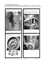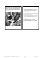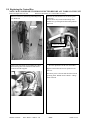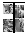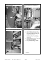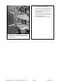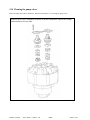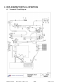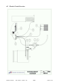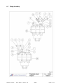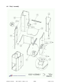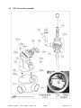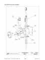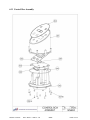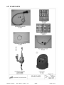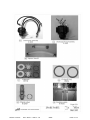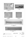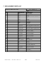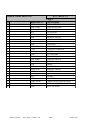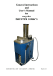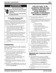
1
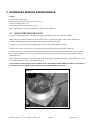
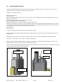
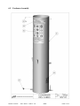
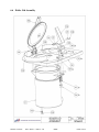
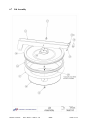
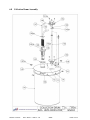
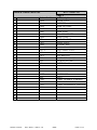
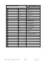
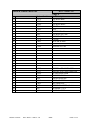
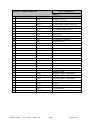
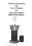
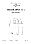
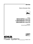
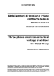
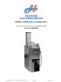
MODEL 10500 (220v) & 10600 (120v)
- SOLVENT RECYCLER WITH TRANSFER PUMPS -
Service Manual
INSTR: 14584NA
REV: Draft 4 / 080218 / CN
APPR:
PAGE: 1/56
Table of Content
1
INTRODUCTION.................................................................................................... 3
1.1
2
SCHEDULED SERVICE & MAINTENANCE .................................................... 4
2.1
2.2
3
Replacing the rubber seal and/or the Teflon sheet ............................................................... 11
Adjusting the lid .................................................................................................................. 12
Inspect or replace the level indicator ................................................................................... 13
Inspect or replace the Foot valve ......................................................................................... 14
Replacing main fuse on 220V unit and 110V unit .............................................................. 15
Replacing Control Box Fuse ................................................................................................ 17
Replacing the Power Box .................................................................................................... 19
Replacing the Control Box .................................................................................................. 21
Replacing the temperature probes ....................................................................................... 22
Replacing the Tap handle and hoses .................................................................................... 24
Replacing the Check valve .................................................................................................. 27
Replacing the Discharge pump (Front pump) ..................................................................... 28
Replacing the Load Pump (Rear pump) .............................................................................. 30
Cleaning the pump valves .................................................................................................... 34
REPLACEMENT PARTS ILLUSTRATIONS .................................................. 35
6.1
6.2
6.3
6.4
6.5
6.6
6.7
6.8
6.9
6.10
6.11
6.12
7
Boiler and condenser ........................................................................................................... 10
REPAIR PROCEDURES...................................................................................... 11
5.1
5.2
5.3
5.4
5.5
5.6
5.7
5.8
5.9
5.10
5.11
5.12
5.13
5.14
6
Distillation problems ............................................................................................................. 6
Unit displayed error codes ..................................................................................................... 7
Pneumatic problems............................................................................................................... 8
Changing Recycling Modes ................................................................................................... 9
Fitting of bags ........................................................................................................................ 9
Resetting “Error Code” .......................................................................................................... 9
COMPONENT DESCRIPTIONS ........................................................................ 10
4.1
5
LOAD PUMP MAINTENANCE .......................................................................................... 4
OIL MAINTENANCE .......................................................................................................... 5
TROUBLE SHOOTING GUIDE ........................................................................... 6
3.1
3.2
3.3
3.4
3.5
3.6
4
List of recommended tools .................................................................................................... 3
Pneumatic Circuit diagram .................................................................................................. 35
Electric Circuit Overview .................................................................................................... 36
Pump Assembly ................................................................................................................... 37
Body Assembly.................................................................................................................... 38
Condenser Assembly ........................................................................................................... 39
Boiler Lid Assembly ............................................................................................................ 40
Lid Assembly ....................................................................................................................... 41
Collection Drum Assembly ................................................................................................. 42
110V Power Box Assembly................................................................................................. 43
220V Power Box Assembly................................................................................................. 44
Control Box Assembly ........................................................................................................ 45
SPARE PARTS ................................................................................................................... 46
REPLACEMENT PARTS LIST .......................................................................... 49
INSTR: 14584NA
REV: Draft 4 / 080218 / CN
APPR:
PAGE: 2/56
1 INTRODUCTION
This manual is written for the Safety Kleen Representative and the Safety Kleen Technician.
The Level One Repairs described can be done by the Safety Kleen Representative.
The Level Two Repairs described can be done by the Safety Kleen Technician.
The Level Three Repairs described should not be done on site.
1.1 List of recommended tools
Philips screw driver
Flat head screw driver
Flexible socket wrench (7 mm.)
Adjustable wrench
Wrenches: 8, 10, 13, 14, 17, 19 (mm. size)
Extended socket 3/8” with ratchet
7 mm nut driver (preferably flexible)
Adjustable pliers
Channel lock
Hex wrench set (mm)
Cutting pliers
Power drill
R2 Bits
Flat nose pliers
Multi meter
INSTR: 14584NA
REV: Draft 4 / 080218 / CN
APPR:
PAGE: 3/56
2 SCHEDULED SERVICE & MAINTENANCE
Weekly:
Clean the boiler compartment.
Rinse the load pump system with clean solvent (see 2.1).
Check the condenser water level.
Recycler bag must be replaced after every cycle.
When “Oil change due” is indicated in the display, change oil (see chapter 2.2).
2.1 LOAD PUMP MAINTENANCE
To prevent blocking of the hoses and seizing of the pump in the loading system, please note the following:
When loading solvent into the boiler using the load pump, there is a risk that thick sludge -often found on the bottom of
containers with contaminated solvent- will block the suction hoses and seize the pump.
It is therefore very important that the loading system is rinsed at the end of the loading procedure.
The best way to do this is to suck some clean solvent through the system until you hear the pump work freely.
If clean solvent is not at hand, the suction tube can be placed at the very surface of the loaded solvent in the recycler where the
solvent is least contaminated (see picture 1). Start the pump and recirculate the solvent through the system until you hear the
pump work freely.
If the load pump is left unused for some time, pumping solvent through the pump as described above will prevent waste material
from drying or hardening in the system and hence block it.
NOTE: THICK UN-DILUTED PAINT MATERIAL MUST NEVER BE PUMPED THROUGH THE LOAD PUMP. IT
WILL BLOCK THE SYSTEM, AND CAN NOT BE DISTILLED IN THE RECYCLER.
Picture 1.
INSTR: 14584NA
REV: Draft 4 / 080218 / CN
APPR:
PAGE: 4/56
2.2 OIL MAINTENANCE
The unit will automatically indicate when it requires an oil change; the display will read, “Oil change due. Press start”. By
pressing the “START” button you can continue to use the recycler.
Oil change is carried out as follows:
Make sure the oil is cold.
Disconnect power.
Place a collection pan/drum under the lower oil tap (see picture 2). The collecting pan/drum must be big enough to take 3,6 US
Gallons (13,6 litres) of oil.
Remove the oil plug (see picture 2) and drain out all of the oil.
Re-place aluminium washer and refit oil plug.
Remove the black oil pipe cover on the left side of top plate (see picture 3).
Refill oil, no more than 3,6 US gallon (13,6 litres) into the oil inlet. Use only original Safety Kleen Diathermic Oil. Use a funnel
to avoid spilling oil onto/into the machine. Minimum oil requirements are: Cracking temperature higher than 320ºC (608 ºF) and
viscosity close to 31cSt at 40ºC (104ºF) and 5,3 cSt at 100ºC (212ºF).
Refit oil pipe cover
Reconnect power.
To remove “Oil change due” message reset the working hours as follows:
Press the “STOP” and “START” button at the same time and keep pressed for 10 seconds. After 10 seconds display will read:
“Select Mode 1”.
Keep “STOP” button pressed. By pressing the “START” button you will be able to loop through the following operations:
Select mode 1 / Select mode 2 / Select mode 3 / Resetting working hours
Release the buttons when the display reading is “Resetting working hours”. By doing this the working hours of the oil is reset
and the machine is ready for use again without “Oil change due” message.
NOTE: It recommended that the heating element is removed and cleaned every second oil change. This will increase the life span
of the heater and reduce the risk of heater malfunction.
Picture 2.
Picture 3.
Oil pipe
cover
Oil pan/drum
Oil inlet
Oil outlet/plug
INSTR: 14584NA
REV: Draft 4 / 080218 / CN
APPR:
PAGE: 5/56
3 TROUBLE SHOOTING GUIDE
Note: The numbers used below, Example: (25), refer to the part numbers in the Pneumatic circuit diagram or spare part
Illustrations.
3.1 Distillation problems
PROBLEM
Unit only distils a
part of the dirty
solvent
POSSIBLE CAUSES
The un-distilled fraction has a
boiling temperature higher
than the maximum operating
temperature of the unit.
Insufficient operating time
Unit is loaded above the
maximum level.
Distillate comes out
dirty
Solvent foams during boiling
Residues have to
loose consistency
Solvent mixture includes a
fraction of solvent with a
boiling temperature higher
than the maximum operating
temperature.
Too much residues in recycler
waste bag.
Heater is scaled
Distillation time is
longer than normal
Waste bags
dissolves
INSTR: 14584NA
Diathermic oil is worn out
Display shows “Oil Change
Due”
Presence of acidified solvent.
Acetates may acidify when
heated.
REV: Draft 4 / 080218 / CN
SOLUTION
LEVEL
Use a solvent with lower boiling
temperature.
1
Change operating mode to Mode 2 or
Mode 3. This increases the power
input during the distillation process
1
Load unit with not more than 5 US
gal.
1
Load a lower quantity than 5 Us gal.
Change operating mode to 1. This
decreases the power input during the
distillation process
Leave dirty solvent to rest for 12-24
hours before starting unit
SEC
0
1
0
1
1
Change to mode 2 or 3 to increase the
power input and the “baking time” See
chapter “The recycling process” in
OEM manual.
Alternatively: replace solvent.
1
0
Replace recycler bag
1
3.4
Change the diathermic oil and clean
the heater
3
Change the diathermic oil
2
Check MSDS. If solvent has acidified
it can not be recycled in the Minimizer
710.2/710.3
1
APPR:
PAGE: 6/56
2.2
3.2 Unit displayed error codes
Note: The numbers used below, Example: (234), refer to the part numbers in the Pneumatic circuit diagram or spare part
Illustrations.
PROBLEM
“ERROR CODE: 1”
“OIL PROBE
FAULTY”
“ERROR CODE: 2”
“H2O PROBE
FAULTY”
“ERROR CODE: 3”
“OIL PROBE
FAULTY”
“ERROR CODE 4-8”
NOT USED
“ERROR CODE: 9”
“OIL PROBE DIFF.”
“ERROR CODE: 10”
“CHECK OIL
LEVEL”
“ERROR CODE: 11”
“CHECK FUSES”
“ERROR CODE 12”
NOT USED
“ERROR CODE: 13”
“CIRCUITS
FAULTY”
“ERROR CODE: 14”
“OIL TEMP TO
HIGH”
POSSIBLE CAUSES
SOLUTION
LEVEL
SEC
One of the 2 temperature probes
(234) for oil is malfunctioning
Replace the two white oil-probes.
(Use 212)
2
5.9
The temperature probe (235)
monitoring the water temperature
is malfunctioning
Replace the grey temperature probe
(Use 212)
2
5.9
One of the 2 temperature probes
(234) for oil is malfunctioning
Replace the two white oil-probes.
(Use 212)
2
5.9
N/A
N/A
N/A
N/A
Check placement of probes. Probes
must be inserted into the white
Teflon tube.
2
5.9
2
2.2
2
5.5
2
5.6
Temperature reading from the two
white temperature probes
(234)(oil) differs too much
Oil level is low, hence causing the
oil temperature to rise too fast
Check oil level. Check for oil leaks.
Refill or replace oil
Oil temperature rises too slow due
to heater (231/232) failure
Check and if needed replace power
board fuse
Check and if needed replace
Control board fuse
Check Heater and if needed replace
heating element
3
N/A
N/A
N/A
N/A
CPU malfunctioning
Replace Control box (218)
2
5.8
Controls have monitored a top
temperature above 380ºF
“ERROR CODE: 15”
“H2O TEMP HIGH”
Grey temperature probe (235)
indicates that the condenser water
temperature is to high
“ERROR”
“LEVEL
INDICATOR”
Signal from the level sensor (143)
in collecting drum is abnormal.
INSTR: 14584NA
Replace the two white oil-probes.
REV: Draft 4 / 080218 / CN
Reset and restart
Change from Mode 3 to Mode 2 or
1
Check the water level in the
condenser
If unit is operating in warm
conditions, leave condenser to cool
down or replace water
Check for accidental grounding of
the indicator
Check cable attachments at top of
indicator
Check for fouling of the indicator.
Clean if necessary
APPR:
3.5
1
0
2
2
5.3
PAGE: 7/56
3.3 Pneumatic problems
Note: The numbers used below, Example: (30), refer to the part numbers in the Pneumatic circuit diagram or spare part
Illustrations.
PROBLEM
POSSIBLE CAUSES
SOLUTION
LEVEL
SEC
THE FOOT PEDAL (30) IS
LEAKING AIR TO THE PUMP
Replace or clean the Foot valve.
LOAD PUMP STRIKES
A hissing noise should come from the
When fitted to the machine, the
ALTHOUGH THE
filter wrapped coupling connected to knob of the Foot valve should be
2
5.4
FOOT PEDAL IS NOT
the pump.
free to move a little bit, and not
PRESSED
This can be caused by dirt collected
firmly jammed.
under the knob of the Foot valve.
THE LOAD PUMP
STRIKES, BUT DOES
VALVES OF THE PUMP (28)
NOT SEEM TO PUMP
MALFUNCTIONING
ANY SOLVENT,
The valves may seal poorly if debris is Dismantle and clean the valves.
2
5.14
ALTHOUGH THE
collected in the valves, preventing
SUCTION TUBE IS
them from sealing against the valve
WELL DOWN INTO
seats.
THE SOLVENT DRUM
AIR DOES NOT GO THROUGH TO
If air comes out through the hose,
2
THE PUMP
THE PUMP IS “DEAD”
the pump is faulty and must be
5.12
To investigate, remove air hose (22 alt.
(APPLICABLE FOR
replaced.
32) from coupling (25). Press the foot
BOTH PUMPS)
If not, there is an air feed problem
5.13
pedal (30). Air should come out
that needs to be investigated.
2
through the hose.
THE LOAD PUMP
STRIKES ONE OR A
FEW TIMES AND
THEN STOPS AND/OR
LOADING SOLVENT
TAKES UNUSUAL
LONG TIME
SUCTION TUBE (43) AND/OR
TUBING IS BLOCKED.
DISCHARGING
(PUMPING) THE
THE CHECK VALVE (31) ON THE
DISTILLED SOLVENT
PUMP IS LEAKING
TAKE UNUSUAL
LONG TIME
DISCHARGE TAPHANDLE
Trigger valve (42) faulty.
MALFUNCTION
The rubber seal (128) under the
LID MECHANISM
Teflon sheet (131) may change shape
LOOSES CLOSING
over time due to pressure and heat.
PRESSURE OVER
As a result, the closing force on the
TIME.
lid handle may change.
UNIT SHOWS SIGNS Lid seal is damaged. Lid seal consists
OF LEAKAGE
of two parts: One rubber seal (128)
AROUND THE
and one white Teflon sheet (131) for
BOILER LID.
universal solvent resistance.
LEVEL INDICATOR
INDICATES THAT
Level indicator rod (143)
DISTILLATE DRUM
malfunctioning due to fouling or
IS FULL ALTHOUGH
faulty cable (233) connection to
IT IS COMPLETELY
control box.
DRAINED
INSTR: 14584NA
REV: Draft 4 / 080218 / CN
Clean suction tube mesh (53) and
tube (43) with clean solvent.
Pump clean solvent through tube
and load pump to dissolve
residues.
1
2.1
If paint residues have been left to
dry or harden load pump
assembly must be replaced.
2
REPLACE CHECK VALVE
2
5.11
Replace tap handle with hoses
2
5.10
Remove one or both of the
rectangular shims (108) situated
under the lid bar.
2
5.2
Check and if necessary clean or
replace lid seal and/or Teflon
sheet.
2
5.1
Check and clean indicator rod.
Check cable shoe connection to
rod. If necessary replace rod
2
5.3
APPR:
PAGE: 8/56
Changing Recycling Modes
The Minimizer 710.2/710.3 has got three different recycling modes that can be used.
Mode 1, Mode 2 and Mode 3.
Mode 1:
This program should be used if the solvent has a high percentage of solvents with low boiling points, e.g. acetone.
Mode 1 uses a low level of power over a longer period of time compared to the default Mode 2. This means that the cycle-time is
slightly longer but the recovery rate higher. Mode 1 also reduces the risk of foaming compared to the default Mode 2.
Mode 2:
DEFAULT MODE
This is the default mode of the unit and is recommended for the normal solvents and contaminants found in a body shop (see
chapter “PERMITTED SOLVENTS”) in the OEM Manual.
Mode 3:
Mode 3 can be used when the acetone level (or other substances with a low boiling temperature) of the solvent is very low. Mode
3 uses an increased level of power during the initial heating of the solvents compared to the default Mode 2.
In Mode 3 the baking time during the last phase of the distillation is longer compared to the default Mode 2. The prolonged
baking time can in some cases make the consistency of the residue more firm.
Changing Mode:
Press the “STOP” and “START” button at the same time and keep pressed for 10 seconds. After 10 seconds display will read:
“Select Mode 1”.
Keep “STOP” button pressed. By pressing the “START” button you will be able to loop through the following operations:
Select mode 1 / Select mode 2 / Select mode 3 / Resetting working hours
Release the “START” AND “STOP” buttons at the preferred mode.
3.4 Fitting of bags
1.
2.
3.
4.
5.
6.
7.
8.
9.
Check that the green light on the control panel is on. This means that the unit is cool and the lid of the boiler can be opened.
Open the lid.
Remove the bag retainer ring.
Remove the used bag. Should it stick to the bottom, press ”START” and let the recycler warm up for 5 minutes. Press
”STOP” and gently pull out the bag and clean the boiler.
Open a new bag and place inside boiler. Tuck the bag well down to the bottom of the boiler.
Squeeze the bag retainer ring and place it down into the bag. The ring must slide into the recess of the boiler
Snap the bag retainer ring into position, in the recess of the boiler.
Make sure the bag is tucked well behind the waste intake manifold
The bag should be replaced before each cycle.
3.5 Resetting “Error Code”
If unit displays and error code note the type of error displayed. Check the trouble shooting chart (3.2) for corrections. To reset the
error code do as follows:
Press “START” AND “STOP” to confirm error message. Display will then read “Turn off power and repair error”.
Turn off power and correct problem. Re-connect power. If unit is cold display will read: “Ready to start Mode X” (i.e. Mode 1, 2
or Mode 3). If unit is hot, display will read “Cooling down”
INSTR: 14584NA
REV: Draft 4 / 080218 / CN
APPR:
PAGE: 9/56
4 COMPONENT DESCRIPTIONS
4.1 Boiler and condenser
How this unit works is described below in 4 steps:
1. The heating element heats the diathermic
oil inside the boiler.
2. The solvent in the boiler vaporises and
escapes out the vapour outlet into the
condenser column.
Boiler
Heating
Element
3. Solvent vapours are cooled by the water in
the condenser column and condenses on its
way through the coil.
INSTR: 14584NA
REV: Draft 4 / 080218 / CN
4. Solvent collects in the collecting drum.
Level is monitored by the level indicator.
Unit can only be restarted if the collecting
drum is empty.
APPR:
PAGE: 10/56
5 REPAIR PROCEDURES
5.1 Replacing the rubber seal and/or the Teflon sheet
Referenced Spare Part: R14650
Referenced illustration: 6.7 Lid Assembly
Unscrew the nut and remove the cover.
Remove the Teflon sheet
Check and if necessary replace rubber seal.
Check and if necessary replace the Teflon sheet.
INSTR: 14584NA
REV: Draft 4 / 080218 / CN
APPR:
PAGE: 11/56
5.2
Adjusting the lid
If lid handle closes without “snapping” lid bar must
be adjusted.
Loosen the two inner bolts securing the lid bar.
Remove a shims piece.
Retighten bolts and check closing “force” of the lid
handle
Check gap between top plate and lid handle bracket.
Gap should be approx. ¼”.
INSTR: 14584NA
REV: Draft 4 / 080218 / CN
APPR:
PAGE: 12/56
5.3 Inspect or replace the level indicator
Referenced illustration: 6.8 Collection Drum Assembly
Remove foot pedal to access collecting drum (ref.
5.4). Remove the clamps securing the lid. Check
and if necessary clean the level indicator.
Remove the indicator cover and check cable
connections.
Note how indicator is attached to drum plug.
Unscrew the two Philips screws with washers to
release the pipe.
Remove top nut on the indicator. Replace rod and
reassemble in reverse order.
INSTR: 14584NA
REV: Draft 4 / 080218 / CN
APPR:
PAGE: 13/56
5.4 Inspect or replace the Foot valve
Referenced Spare Part: R14640
Referenced illustration: 6.1 Pneumatic Circuit Diagram
Unscrew four Philips screws to loosen the pedal
plate. Disconnect hoses from fittings.
Lift the pedal and unscrew the two Philips screws to
remove the foot-valve.
Check the foot-valve and if necessary replace it.
Route the longer hose to the left.
INSTR: 14584NA
REV: Draft 4 / 080218 / CN
APPR:
PAGE: 14/56
5.5 Replacing main fuse on 220V unit and 110V unit
NOTE: MAIN POWER MUST BE DISCONNECTED BEFORE ANY WORK ON THE UNIT
Referenced Spare Part: R13380(110V) R13390(220V) Referenced illustration: 6.9 (110V power box) alt. 6.10 (220V Power box)
Remove side door by unhooking and sliding along
rear handle bar
Remove the power box lid by turning the lid anti
clockwise.
220 V UNIT ONLY!
Main fuse is situated next to the green terminal.
Fuse data 250V Fuse 5x20 10Amp Slow.
Example: Little fuse part no. 218.010 T
Main fuse
INSTR: 14584NA
REV: Draft 4 / 080218 / CN
NOTE:
Intrinsically safe fuse
is solded to circuit
board and is NOT
replaceable. If fuse has
burnt the complete
Power box assembly
must be replaced
APPR:
PAGE: 15/56
110 V UNIT ONLY!
Main fuse is covered by an insulating sheet (white)
Open sheet by un-hooking the tongue of the sheet
from centre screw.
Slide tongue of
screw
110 V UNIT ONLY!
Main fuse is now accessible. Fuse must be replaced
with original fuse. Fuse data: Littelfuse KLK 20
NOTE:
Intrinsically safe fuse
is solded to circuit
board and is NOT
replaceable. If fuse has
burnt the complete
Power box assembly
must be replaced
INSTR: 14584NA
REV: Draft 4 / 080218 / CN
APPR:
PAGE: 16/56
5.6 Replacing Control Box Fuse
NOTE: MAIN POWER MUST BE DISCONNECTED BEFORE ANY WORK ON THE UNIT
Referenced Spare Part:R14630 (110V) R13990 (220V)
Remove side door by unhooking and sliding along
rear handle bar
Referenced illustration: 6.11 Control Box Assembly
Unscrew the four small flat head screws securing
two green connectors.
Unscrew to remove
Unscrew the four small screws holding the control
box to the top plate. The control box can now be
removed from the top plate
INSTR: 14584NA
REV: Draft 4 / 080218 / CN
Unscrew the eight screws securing the control box
cover and remove the Control box lid.
APPR:
PAGE: 17/56
The control box fuse is situated under the top circuit
board. Check fuse and replace if necessary. Fuse
type: 250V Fast acting 200mA (5x20)
Example Littlefuse part No: 217.200 F
- Reverse operation to fit the new Power Box -
Fuse data: 250V Fuse 5x20 200mA Fast.
Example: Little fuse part no. 217.200 F
INSTR: 14584NA
REV: Draft 4 / 080218 / CN
APPR:
PAGE: 18/56
5.7 Replacing the Power Box
NOTE: MAIN POWER MUST BE DISCONNECTED BEFORE ANY WORK ON THE UNIT
Referenced Spare Part: R13380(110V) R13390(220V) Referenced illustration: 6.9 (110V power box) alt. 6.10 (220V Power box)
Remove side door by unhooking and sliding along
rear handle bar
Unscrew the two small screws for the small green
connector.
Picture shows early model Teflon tubing. Later
models have got corrugated Teflon tubing without
pipe bend.
Unscrew to remove
Remove heater lid and disconnect the two leaders
and ground cable. Note position of leaders and
position of the washers.
INSTR: 14584NA
REV: Draft 4 / 080218 / CN
Unscrew the two bolts holding the power box
assembly
APPR:
PAGE: 19/56
Unscrew the large aluminium gland nut securing the
power box to the heater. Ensure that only the gland
nut rotates when un-screwing. Cable conduit and
the entry reduction fitted to the heater should not
rotate. These may have to be fixated with the aid of
a second pair of pliers.
- Reverse operation to fit the new Power Box -
1.
Remove and replace the Power box assembly.
Start by fitting the gland nut to the heater
loosely by hand.
2.
Fit the two bolts and reconnect the green plug.
3.
Tighten the heater gland nut.
4.
Fit the leaders to the heater. Make sure cables
are clear from the heating element rods and
terminals.
INSTR: 14584NA
REV: Draft 4 / 080218 / CN
5.
Tighten nuts and ground screw gently.
6.
Fit the heater lid. Tighten lid firmly by hand.
APPR:
PAGE: 20/56
5.8 Replacing the Control Box
NOTE: MAIN POWER MUST BE DISCONNECTED BEFORE ANY WORK ON THE UNIT
Referenced Spare Part: R11188
Referenced illustration: 6.11 Control Box Assembly
Remove side door by unhooking and sliding along
rear handle bar
Unscrew the four small screws for the two green
connectors.
Picture shows early model Teflon tubing. Later
models have got corrugated Teflon tubing without
pipe bend.
Unscrew to remove
Unscrew the four small screws holding the control
box to the top plate. The control box can now be
removed from the top plate
- Reverse operation to fit the new control Box Replace Control box and reverse operation to fit
new box.
Reconnect power to the unit and check the selected
operating mode. Default mode is Mode 2. Change
mode if desired.
INSTR: 14584NA
REV: Draft 4 / 080218 / CN
APPR:
PAGE: 21/56
5.9 Replacing the temperature probes
NOTE: MAIN POWER MUST BE DISCONNECTED BEFORE ANY WORK ON THE UNIT
Referenced Spare Part: R13980
Referenced illustration: 6.2 Electric Circuit Overview
Remove side door by unhooking and sliding along
rear handle bar.
Picture shows the position of the temperature
probes. The two white oil temperature probes
(No.1) are inserted into a white Teflon tube witch
then is inserted into the boiler plunge tube (inside
boiler).
The grey water temperature probe (No.2) is inserted
into the small pipe welded to the vapor outlet of the
condenser. No 3 shows the position of the probe
connector
Please note how probes are secured with cable ties.
3. Green connector
3.Green connector
1. Oil probes
1. Oil probes
2. Water probe
2. Water probe
Unscrew the two small screws on the large green
connectors.
Open the green connector by gently lifting the three
snap hooks.
Unscrew to remove
INSTR: 14584NA
REV: Draft 4 / 080218 / CN
APPR:
PAGE: 22/56
Fitting new oil probe/probes
Connecting point No:
1 2 3 4 5 6 7
8
9
10
The probes are connected from the right as follows:
White oil probe 1 (connecting point. 9&10)
Grey water probe (connecting point. 7&8)
White oil probe 2 (connecting point. 5&6)
Function of the probes is checked by measuring the
resistance between the red and white / brown and
white lead. Resistance should be 1080Ω ± 100 Ω
If probe leads are short circuited (near 0 Ω) or
disconnected (Off limit) probe must be replaced.
Insert the oil probes into the white Teflon hose.
Ensure that probes are side by side inside the hose.
Push the white Teflon hose with probes all the way
into the boiler plunge tube (see picture).
Fit the cable tie through the plunge tube hole and
secure the two white cables firmly.
Fitting new water probe
Insert the grey probe into the small pipe. Secure the
cable with the cable tie.
INSTR: 14584NA
REV: Draft 4 / 080218 / CN
APPR:
PAGE: 23/56
5.10 Replacing the Tap handle and hoses
Referenced Spare Part: R14620
Referenced illustration: 6.1 Pneumatic Circuit Diagram
Unscrew the four screws holding the foot-valve
plate.
Push the foot-valve plate aside and pull out the
collecting drum.
Remove the four clips securing the lid and loosen
nut and screw to release the ground cable.
Bend the clip to release the ground cable.
INSTR: 14584NA
REV: Draft 4 / 080218 / CN
APPR:
PAGE: 24/56
Release the ground cable secured to the tubing.
Loosen screw and nut to release the hose clamp.
Disconnect the yellow hose from the fitting.
Disconnect the blue hose from the T-fitting.
INSTR: 14584NA
REV: Draft 4 / 080218 / CN
APPR:
PAGE: 25/56
Loosen the hose clamp on the white hose.
Pull the white hose off of the pump assembly. Twist
and turn while pulling. White hose is fitted to a
barbed brass piece and requires some pulling force
in order to come off. Support pump and fittings
while pulling to avoid damage.
The large hose clamp securing the metal jacket
must be re-used on new assembly.
This picture shows a correctly tightened joint.
NOTE to what level the rubber bushing is
deformed, securing a tight joint.
Now run a test of the pump, and make sure there are
no leaks of air or solvent.
Reverse order to fit the new Tap handle
INSTR: 14584NA
REV: Draft 4 / 080218 / CN
APPR:
PAGE: 26/56
5.11 Replacing the Check valve
Referenced Spare Part: R13929
Referenced illustration: 6.2 Pump Assembly
Check vale is integrated with discharge pump to
avoid accidental spillage if tap handle is dropped
(Anti Siphon effect).
Remove the black hose from the check valve.
INSTR: 14584NA
REV: Draft 4 / 080218 / CN
Use a 17 mm wrench to unscrew the valve.
Replace valve and fit black hose.
APPR:
PAGE: 27/56
5.12 Replacing the Discharge pump (Front pump)
Referenced Spare Part: R14080
Referenced illustration: 6.1 Pneumatic Circuit Diagram
Disconnect the yellow hose from the fitting. Cut the
white hose from the tap handle as close to the pump
as possible.
Disconnect the black hose from the check valve.
Cut the remaining white hoses as close to the pump
as possible. NOTE the position of the different
white hoses
INSTR: 14584NA
REV: Draft 4 / 080218 / CN
Remove the pump by unscrewing the two Allen
screws for the pump bracket.
APPR:
PAGE: 28/56
Old pump removed
Fit new rubber hose piece with clamps from the
spare part onto the cut hoses. Make sure that the
hose is pushed through to the end of the rubber
piece.
Fit the hoses back onto the new pump. Make sure
hoses are pushed all the way onto the brass pieces.
One should hear/feal two “snaps” as hose passes the
barb on the brass piece.
This picture shows a correctly tightened joint.
NOTE to what level the rubber bushing is
deformed, securing e tight joint.
Now run a test of the pump, and make sure there are
no leaks of air or solvent.
Reverse order to fit the new Tap handle
INSTR: 14584NA
REV: Draft 4 / 080218 / CN
APPR:
PAGE: 29/56
5.13 Replacing the Load Pump (Rear pump)
Referenced Spare Part: R14070
Referenced illustration: 6.1 Pneumatic Circuit Diagram
Remove side door by unhooking and sliding along
rear handle bar
Unscrew the four screws holding the foot-valve
plate.
Push the foot-valve plate aside and pull out the
collecting drum.
Remove the black hose (from the rear pump) from
the fitting to free pump from foot pedal/blue hose.
INSTR: 14584NA
REV: Draft 4 / 080218 / CN
APPR:
PAGE: 30/56
Remove suction tube and hose from the side of the
unit.
Unscrew the inlet fitting. Use a 19mm spanner (or
adjustable) and hold the L-piece (rear) by hand.
INSTR: 14584NA
REV: Draft 4 / 080218 / CN
Cut the two cable ties securing the three hoses
(black, black, white). Hoses are situated in the rear,
behind the right panel.
Unscrew the two sheet metal screws securing the
hose support bar. Use a Philips screwdriver.
APPR:
PAGE: 31/56
Push the rear of the hose support bar to the side to
free the two black hoses.
Unscrew the two bolts holding the pump bracket.
Loosen the hose clamp at the rear T-piece, under
the top panel. Remove hose and fittings from Tpiece.
A. Reverse operation to fit the new Load Pump 1.
2.
3.
4.
5.
6.
Start by fitting new pump to rear panel
Push the long black hose firmly onto the
brass fitting and tighten hose clamp. One
should hear/feel two snaps as hose passes
the barb on the brass piece.
Extend hose with L-piece and plugged
hose upwards between hose support bar
and side panel.
Fit the two sheet metal screws to secure the
hose support bar to right panel.
Re-fit Teflon tape to the 3/8” coupling.
Fit L-piece through the right side panel
Continued…
INSTR: 14584NA
REV: Draft 4 / 080218 / CN
APPR:
PAGE: 32/56
-B Continue to reverse operation 1.
2.
3.
4.
5.
6.
Re-fit Teflon tape to suction tube L-piece.
Fit the suction tube to the inlet fitting.
Fit black 6mm pump hose to the foot
pedal/blue hose
Place collection drum inside unit and fit
the four screws to secure the foot pedal.
Fit the rear right door.
Test pump by pushing the foot pedal.
Fit the two cable ties included in the Load Pump
Assembly to secure all three hoses (White, Black,
Black). Bottom tie is lead through the two holes of
the right side panel.
INSTR: 14584NA
REV: Draft 4 / 080218 / CN
APPR:
PAGE: 33/56
5.14 Cleaning the pump valves
Referenced Spare Part: R6336 and R9178 Referenced illustration: 5.14 Cleaning the pump valves
Remove the 8 screws, dismantle as shown, clean the components, replace the O-rings
and assemble in reverse order.
INSTR: 14584NA
REV: Draft 4 / 080218 / CN
APPR:
PAGE: 34/56
6 REPLACEMENT PARTS ILLUSTRATIONS
6.1 Pneumatic Circuit diagram
INSTR: 14584NA
REV: Draft 4 / 080218 / CN
APPR:
PAGE: 35/56
6.2 Electric Circuit Overview
INSTR: 14584NA
REV: Draft 4 / 080218 / CN
APPR:
PAGE: 36/56
6.3 Pump Assembly
INSTR: 14584NA
REV: Draft 4 / 080218 / CN
APPR:
PAGE: 37/56
6.4 Body Assembly
INSTR: 14584NA
REV: Draft 4 / 080218 / CN
APPR:
PAGE: 38/56
6.5 Condenser Assembly
INSTR: 14584NA
REV: Draft 4 / 080218 / CN
APPR:
PAGE: 39/56
6.6 Boiler Lid Assembly
INSTR: 14584NA
REV: Draft 4 / 080218 / CN
APPR:
PAGE: 40/56
6.7 Lid Assembly
INSTR: 14584NA
REV: Draft 4 / 080218 / CN
APPR:
PAGE: 41/56
6.8 Collection Drum Assembly
INSTR: 14584NA
REV: Draft 4 / 080218 / CN
APPR:
PAGE: 42/56
6.9 110V Power Box Assembly
INSTR: 14584NA
REV: Draft 4 / 080218 / CN
APPR:
PAGE: 43/56
6.10 220V Power Box Assembly
INSTR: 14584NA
REV: Draft 4 / 080218 / CN
APPR:
PAGE: 44/56
6.11 Control Box Assembly
INSTR: 14584NA
REV: Draft 4 / 080218 / CN
APPR:
PAGE: 45/56
6.12 SPARE PARTS
INSTR: 14584NA
REV: Draft 4 / 080218 / CN
APPR:
PAGE: 46/56
INSTR: 14584NA
REV: Draft 4 / 080218 / CN
APPR:
PAGE: 47/56
INSTR: 14584NA
REV: Draft 4 / 080218 / CN
APPR:
PAGE: 48/56
7 REPLACEMENT PARTS LIST
10500 & 10600 Parts List
Rev 2 / 080218 / CN
Page 1
No.
1
2
3
Hedson Part No.
14241
5355
10212
4
5
6
7
8
9
10
11
12
13
14
15
16
17
18
19
20
21
22
23
24
25
26
27
28
29
30
13531
11278
11242
12624
4642
2827
13528 ;0,1m
11809
13528 ;0,15m
13528 ;0,2m
10216 ;1,15m
13529 ;1,15m
5042 ;0,78m
10216 ;0,7m
5042 ;0,67m
3517 ;0,6m
10555
5101-1 ;0,07m
5101-1 ;0,47m
6990
13738
8363
2164-1 ;0,12m
6944 ;0,12m
6160-M
8272
2366
INSTR: 14584NA
REV: Draft 4 / 080218 / CN
Part Description
HOSE CLAMP
PIECE OF HOSE
NIPPLE
HOSE CLAMP-REPLACED BY
NO.1
NIPPLE
T-PIECE
COUPLING
BUSHING
PLUG
HOSE Ø16- REPLACED BY NO.54
STEAM PIPE
HOSE Ø16- REPLACED BY NO.54
HOSE Ø16- REPLACED BY NO.55
HOSE Ø17 WHITE
SILICONE HOSE Ø12
HOSE Ø17 BLACK
HOSE Ø17 WHITE
HOSE Ø17 BLACK
HOSE Ø6 BLACK
T-PIECE
HOSE Ø6 BLUE
HOSE Ø6 BLUE
T-PIECE
Y-COUPLING
COUPLING, DRILLED
HOSE Ø6 BLACK
HOSE Ø6 YELLOW
PUMP
COUPLING
FOOT-VALVE
APPR:
PAGE: 49/56
10500 & 10600 Parts List
Rev 2 / 080218 / CN
Page 2
No.
31
32
33
34
35
36
37
38
39
40
41
42
43
44
45
46
47
48
49
50
51
52
53
54
55
56
Hedson Part No.
13929
6944 ;1,52m
5101-1 ;1,76m
9197
10267
9598
4270
2018
2984
10216 ;1,34m
13479
8262
13607
5042 ;2,15m
5042 ;0,66m
11811
3926
8257
10216 ;0,7m
13717
13482
6871
10760
14805; 0,21m
14805; 0,42m
14847
INSTR: 14584NA
REV: Draft 4 / 080218 / CN
Part Description
CHECK VALVE
HOSE Ø6 YELLOW
HOSE Ø6 BLUE
T-COUPLING
COUPLING
AIR REGULATOR
ELBOW COUPLING
FILTER
COUPLING
HOSE Ø17 WHITE
COUPLING, DRILLED
VALVE
SUCTION PIPE
HOSE Ø17 BLACK
HOSE Ø17 BLACK
TAP PIPE
NIPPLE
COUPLING
HOSE Ø17 WHITE
JACKET
JACKET
JACKET
STRAINER
CORRUGATED TEFLON HOSE
CORRUGATED TEFLON HOSE
PIECE OF HOSE
APPR:
PAGE: 50/56
10500 & 10600 Parts List
Rev 1 / 070403 / TB
Page 3
No.
61
62
63
64
65
66
67
68
69
70
71
72
73
74
75
76
77
78
79
80
81
82
83
84
85
86
87
88
89
90
INSTR: 14584NA
Hedson Part No.
10968
10963
10966
10967
10981
11125
10988
6276
13413
10989
10979
8561-E
4448
10972
5030
8414
9429
Part Description
FLOOR PLATE
LEFT SIDE
REAR LEFT SIDE
RIGHT SIDE
REAR DOOR
ISOLATION PLATE
HOSE GUIDE
PUMP BRACKET
FRONT PLATE
SUPPORT BAR
HANDEL BAR
FOOT-PEDAL PLATE
CLIP
BOX BRACKET
SCREW RXK 4,2 x 6,5
LOCKING NUT M6
SCREW M6 x 10
10977
9619
13585
13574
13591
13521
CONDENSER
RIVET
LABEL "GENERAL WARNING"
LABEL "USER GUIDE"
LABEL "HAZARDOUS VOLTAGE"
PLUG
REV: Draft 4 / 080218 / CN
APPR:
PAGE: 51/56
10500 & 10600 Parts List
Rev 1 / 070403 / TB
Page 4
No.
91
92
93
94
95
96
97
98
99
100
101
102
103
104
105
106
107
108
109
110
111
112
113
114
115
116
117
118
119
120
INSTR: 14584NA
Hedson Part No.
11079
13523
6596
13526
13206
11578
13633
6588
8307
5363
10961
13417
11282
11281
11283
13524
13513
11289
8984
4246
REV: Draft 4 / 080218 / CN
Part Description
BOILER
SCREW M6 x 65
SCREW M6 x 50
SCREW M5 x 65
SCREW M8 x 20
SPRING NUT
SPRING
SCREW M8 x 90
LOCKING NUT M5
LOCKING NUT M6
TOP PLATE
BOILER SUPPORT
LID BRACKET
LOCKING HANDLE
HANDLE BRACKET
LID ASSEMBLY
WASHER 8 x 22 x 1,5
SPACER
PLUG
ALUMINUM WASHER
APPR:
PAGE: 52/56
10500 & 10600 Parts List
Rev 1 / 070403 / TB
Page 5
No.
121
122
123
124
125
126
127
128
129
130
131
132
133
134
135
136
137
138
139
140
141
142
143
144
145
146
147
148
149
150
INSTR: 14584NA
Hedson Part No.
11279
13473
11284
11285
13525
3130
6552
11199
13778
13893
13742
13104
Part Description
LOCKING BAR
LID
LOCKING ROLL
SHAFT
11732
11733
11554
10169
8124
10203
13435
2657
2157
2445
DESTILLATE CONTAINER
DESTILLATE CONTAINER LID
LEVEL INDICATOR
TAPERED PLUG
DRUM ADAPTER
HOSE ADAPTER
SUCTION PIPE
SCREW PLASTITE 4,2 x 16
WASHER 5,5 x 12
LOCK WASHER
REV: Draft 4 / 080218 / CN
CLIP
SCREW M8 x 50
LOCKING NUT M8
RUBBER SEAL
COVER
SPACER SCREW
TEFLON SHEET
DOMED NUT M6
APPR:
PAGE: 53/56
10500 & 10600 Parts List
Rev 1 / 070403 / TB
Page 6
No.
151
152
153
154
155
156
157
158
159
160
161
162
163
164
165
166
167
168
169
170
171
172
173
174
175
176
177
178
179
180
INSTR: 14584NA
Hedson Part No.
5100
11292
14471
14472
10533
6836
11133
3221
8349
3514
5119
Part Description
SCREW 4,2 x 16
DESTILLATE PIPE
LEVEL INDICATOR ADAPTER
11741
13340
13483
13475
13484
10971
13488
14202
14203
14505
EX-BOX
POWER CARD
SIGNAL CABEL ASSEMBLY
POWER CABEL ASSEMBLY
HEATER CABEL ASSEMBLY
BOX PLATE
CLAMP
POWER CARD SPACER
FUSE BRIDGE
FUSE 20A TYPE KLK (ETL APPR.)
REV: Draft 4 / 080218 / CN
INDICATOR HOOD
RETAINING RING SGA 13
RETAINING RING SGA 16
LID CLIPS
BRASS PIPE
STARLOCK WASHER
SCREW M5 x 10
CABLE CLAMP
APPR:
PAGE: 54/56
10500 & 10600 Parts List
Rev 1 / 070403 / TB
Page 7
No.
181
182
183
184
185
186
187
188
189
190
191
192
193
194
195
196
197
198
199
200
201
202
203
204
205
206
207
208
209
210
INSTR: 14584NA
Hedson Part No.
5054
9973
8307
13297
13486
2445
5387
13487
14204
14206
13320
6923
13984
14214
Part Description
SCREW M4 x 10 FZB
SCREW M4 x 16 FZB
LÅSMUTTER NYLON M5 FZB
LÅSMUTTER NYLON M4 FZB
SET SCREW M5 x 20
LOCK WASHER 5.3x10 fzb
SCREW M5 x 10 FZB
WASHER 5,3 x 10 x 1 FZB
FUSE CLIP
FUSE PLATE
POWER CARD
FLANGE NUT M5
FUSE 10A 5x20 SLOW
MYLAR SHEET
11186
11187
13371
11268
11575
13527
6341
6935
13985
HOOD CONTROL BOX
BOTTOM CONTROL BOX
CONTROL CARD
OVERLAY
GUIDE PLATE
O-RING
SCREW PLASTITE Z 8-16x25
SCREW M3x10
FUSE 200mA 5x20 FAST
REV: Draft 4 / 080218 / CN
APPR:
PAGE: 55/56
10500 & 10600 Parts List
Rev 2 / 080218 / CN
Page 8
No.
211
212
213
214
215
216
217
218
219
220
221
222
223
224
225
226
227
228
229
230
231
232
233
234
235
236
Hedson Part No.
R14620
R13980
R13380
R13390
R14630
R13990
R14640
R11188
R14070
R14080
R9178
R6336
R14660
13474
R14650
13602
R10760
R10750
R13929
R14610
14158
11734
13470
13718
13719
R10780
INSTR: 14584NA
REV: Draft 4 / 080218 / CN
Part Description
TAP HANDLE ASSEMBLY
TEMPERATURE PROBE KIT
POWER BOX ASSEMBLY 110V
POWER BOX ASSEMBLY 220V
110V FUSE KIT
220V FUSE KIT
FOOT VALVE WITH HOSE
CONTROL BOX
LOAD PUMP ASSEMBLY
DISCHARGE PUMP ASSEMBLY
VALVE-SET
O-RING (2 Pcs)
PANEL ACCESSORIES
AIR REGULATOR-SET
LID GASKET KIT
RETAINING RING
SUCTION TUBE STRAINER
RECYCLER BAGS (20 Pcs)
CHECK-VALVE
DOCKING VALVE
HEATER 128V 1700W
HEATER 240V 1800W
LEVEL INDICATOR CABLING
TEMPERATURE PROBE WHITE
TEMPERATURE PROBE GREY
VAPOUR HOSE KIT (TEFLON)
APPR:
PAGE: 56/56