1
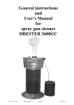
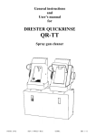
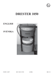
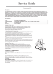
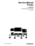
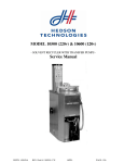
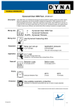
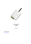
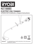
General instructions
and
User’s manual
for
DRESTER 9000-TT-B
Spray gun cleaner
INSTR: 15125
REV: 090428/TB
GODK:
SID: 1/19
**********ENGLISH**********
TABLE OF CONTENTS:
1. GENERAL INFORMATION
Page:
3. ASSEMBLY
3. PLACING THE UNIT
4. INSTALLATION
5. SAFETY INFORMATION
6. WARRANTY
6. TECHNICAL DATA
2. AUTOMATIC GUN CLEANER
(LEFT SIDE OF UNIT)
7. PURPOSE OF THE MACHINE
7. PERMITTED SOLVENTS
7. PERMITTED DRUMS
7. COLLECTING TRAY
8. PREPARATIONS FOR USE
9. OPERATING INSTRUCTIONS
9. SAFETY INFORMATION
9. SERVICE
3. MANUAL GUN CLEANER FOR WATER-BASED SOLVENTS
(RIGHT SIDE OF UNIT)
10. PURPOSE OF THE MACHINE
10. PERMITTED SOLVENTS
10. OPERATING INSTRUCTIONS
11. CHANGING THE FILTER
11. OPERATION WITHOUT TAP-WATER CONNECTION
2
1. GENERAL INFORMATION
CAUTION
Read this User’s Manual before using the DRESTER 9000-TT-B.
Do not use the equipment unless you fully understand this User’s Manual.
This User’s Manual must be available when using the unit.
GENERAL INFORMATION
This User’s Manual will provide important information concerning the DRESTER 9000-TT-B, and will describe how to use the gun
cleaner safely. Read the entire User’s Manual before using the unit. For safe use, it is important that the unit, the drums and the
solvent are of the described specifications, and that they are handled properly. It is important that you follow the instructions
carefully.
The DRESTER 9000-TT-B utilizes drums of solvent for cleaning. Drums and solvent for use with the unit is not provided by
Hedson Technologies. On the market there are numerous drums and solvents, and Hedson Technologies cannot account for them
all. Never use any solvent unless it is provided with an MSDS (Material Safety Data Sheet). Read the MSDS carefully, and follow
all the instructions and procedures provided in the MSDS. Only use drums as specified in the instructions. More information
regarding allowed drums and solvents can be found under chapters PERMITTED SOLVENTS and PERMITTED DRUMS.
ASSEMBLY
The unit is supplied complete in a box. To assemble it, simply follow the enclosed sequence of pictures (10516).
PLACING THE UNIT
Area classification
The DRESTER 9000-TT-B can be placed in locations classified as Class 1, Division 1 / Zone 1.
If the DRESTER 9000-TT-B is installed in locations classified as Class 1, Division 2 / Zone 2, or in unclassified locations, the area
within 5 feet from the unit is to be classified as Class 1, Division 1 / Zone 1. Outside said area, another 3 feet is to be classified as
Class 1, Division 2 / Zone 2 (see picture 3).
Within these classified areas of Class 1, Division 1 / Zone 1 and Class 1, Division 2 / Zone 2, all equipment, such as electrical items
and ventilation equipment, must be approved for the applicable Division / Zone. Equipment that generates naked flames or sparks
(e.g. welding or grinding equipment) may not be used in this area. Smoking is not permitted. If in any doubt, contact the local fire
service authorities for advice.
Fire extinguisher
A fire extinguisher (dry chemical type ABC, dry chemical type BC, foam, carbon dioxide or Halon) must always be kept nearby
when working with flammable solvents. Do not use water.
Drain water protection
The unit must be placed in a location where any accidental leakage of solvent is prevented from spreading into the drain water
system.
3
INSTALLATION
Compressed air
The unit must be connected to compressed air of 7-12 bar (110-180 psi). When in use, the unit consumes 150 litres/min (6 cfm) of
air (450 litres/min (16 cfm) if connected to a DRESTER AIRVENT 10110). The air connection is on the side of the unit (see item
10 in Picture 1). To prevent pressure drops, the air line and couplings must be adequately dimensioned. The regulator on the unit
is pre-set to 6.5 bar (100 psi). This is the optimal setting and must not be altered.
The compressed air supplied to the unit must be clean and dry. If it is not first led through a water trap and filter, it may cause
damage to the pneumatic components of the unit, which will invalidate any warranty claims.
Fit a connector to the air line on the left side of the unit (see item 1 in Picture 1). This air line is intended to blow out the spraygun after the cleaning procedure.
Tap water connection
Connect a hose for tap water to the water inlet (No.15 picture 1).
Ventilation
There are two different options for the unit’s ventilation. For all three options, it must be ensured that the speed of the air flow at
the opening of the hood is at least 0.5 m/s (this corresponds to a ventilation volume of 400 m3/h (250 cfm)). The ventilation must
be connected in such a way as to ensure the grounding of all parts.
Option 1: Connect the hood (see item 11 in Picture 1) directly to a metal ducting, which is in turn connected to a ventilation
system approved for Zone 1. The ventilation volume must be at least 400 m3/h (250 cfm).
Option 2: Fit an air-driven DRESTER AIRVENT 10110 to the hood and connect this to a metal ducting. This ducting can either
lead outdoors or be connected to a ventilation system approved for Zone 1. The ducting must have a smooth inner surface, may
not be longer than 15 metres and shall be installed so that it is as straight as possible.
Grounding
Securely ground the unit, using the main ground clamp on the back of the unit (see picture 4, item 1). Also ground the drums, using
the grounding clamps (see picture 4, item 2). If using painted drums, scrape off some paint to ensure proper contact for the ground
clamps.
Operating instructions
Operating instructions should be formulated on the basis of this manual and translated into the language spoken by the employees.
It should always be available close to the machine. To avoid confusion, the employees must be informed about the solvent
currently being used in the machine.
4
SAFETY INFORMATION
Hazards may arise from improper use of the DRESTER 9000-TT-B. Hazards may also arise from improper choice/handling of
drums or solvent. In order to maintain the high safety standard of the unit, it is important that these instructions are followed.
-
Do not operate the unit until you have read and fully understood this entire User’s Manual.
The unit should be intalled as described in the instructions.
The unit should be used as described in the instructions.
The unit should be maintained as decribed in the instructions.
Only original spare parts may be used.
This User’s Manual must be available and in legible condition in close proximity to the unit. Every user shall know where
to find the User’s Manual.
Operating instructions should be formulated on the basis of these General Instructions and User’s Manual for DRESTER
9000-TT-B, and translated into the language spoken by the employees.
Do not modify or in any way alter the unit.
Do not operate the unit unless it is properly vented. Do not operate the unit if the extraction of vapors is insufficient.
Avoid contact with liquid and vapor. Refer to the solvents’ MSDS (Material Safety Data Sheet).
Wear chemical goggles or similar, to protect your eyes. Wear chemical-resistant gloves to prevent skin-contact. Wear
chemical-resistant clothing to protect against spills or splash.
Personnel suffering from respiratory problems or allergies to solvents used, must not operate the machine.
Clean up spills immediately. Solvent vapors are heavier than air and can spread a long way. They may also collect in pits
or other low areas.
Do not smoke, eat or drink while close to the unit.
The unit is equipped with a safety valve that will interrupt the automatic wash cycle if the lid is opened before the wash
cycle is completed.
A fire extinguisher (dry chemical type ABC, dry chemical type BC, foam, carbon dioxide or Halon) must always be kept
nearby when working with flammable solvents. Do not use water.
Spray guns cleaned in the unit must be suitable for cleaning in gun cleaning machines classified as Class 1, Division 1 /
Zone 1. If unsure, please contact the spray gun manufacturer.
The unit must be properly grounded using the attached clamps. The solvent drums should be properly grounded using the
attached clamps. If plastic drums are used, the openings should be wiped off with a damp cloth, to avoid static electricity,
before inserting or removing any hoses or other equipment.
5
WARRANTY
Hedson Technologies AB will replace all faulty parts on the DRESTER 9000-TT with new parts in accordance with the
“Warranty Terms for Hedson Technologies AB No. 7.2-8”. This warranty only remains valid if the machine is used in the
prescribed manner, and it does not cover the cost of repairs other than parts. Always state the machine’s serial number and year of
manufacture if making a claim under warranty. These can be found on the machine’s silver-coloured rating plate. The warranty
terms may vary from country to country. Hedson North America, Inc. can provide you with details.
TECHNICAL DATA
Manufactured by:
Hedson Techologies AB
Hammarvagen 4
232 37 Arlov
Sweden
Tel: +46 40- 53 42 00
Distributed in North America by
Hedson North America, Inc.
466 Speers Rd. 3rd Floor
Oakville, Ontario
Canada L6K 3W9
Phone: 905 339 2800
Fax: 416-352-5738
Toll Free: 866-478-4328
E-mail: [email protected]
Type of machine:
Permitted solvents:
Liquid volume of machine:
Compressed air needed:
Air consumption:
Extraction capacity needed:
Pump capacity:
Solvent pressure:
Water flow through
cleaning brush:
Weight:
Overall dimensions:
Extractor flange diameter:
Sound pressure level:
DRESTER 9000-TT-B
See section “Permitted solvents”
35 litres (9,25 gallons) of water, solvent depending on drum size
7-12 bar (110-180 psi)
150 l/min (6 cfm) (450 litres/min (16 cfm) with DRESTER AIRVENT 10110)
400 m3/h (250 cfm)
10 litres (2,65 gallons) /min
2 bar (30 psi)
1.5-2 litres (0,4-0,53 gallon) /min
85 kg (182 lb)
1470 mm (58”) high, 1180 mm (46,5”) wide, 570 mm (22,5”) deep (at the floor)
125 mm (5”)
<70 dB(A)
6
2. AUTOMATIC GUN CLEANER
(LEFT SIDE OF UNIT)
PURPOSE OF THE MACHINE
This side of the machine is intended to clean air-driven spray-guns using either thinner-based solvents or water-based solvents.
PERMITTED SOLVENTS
Solvent for use with the DRESTER 9000-TT-B is not provided by Hedson Technologies. On the market, there are numerous
solvents and these instructions cannot account for them all. Only use the unit with solvents intended for spray gun cleaning, such as
lacquer thinner. Lacquer thinner is a generic term for solvent mixtures, commonly containing such ingredients as e.g. Acetone,
Toluene, Xylene and iso-Butanol. The unit can be used with solvents classified as Group IIA according to IEC 60079-20. The unit
can also be used with water. All solvents must have a pH value between 4 and 10. Be sure not to mix water-based solvents with
thinner-based solvents. It is important that all users are informed of what solvent is being used, at all times.
Never use any solvent if it is not provided with an MSDS (Material Safety Data Sheet). Read the MSDS carefully, and follow all
the instructions and procedures provided in the MSDS. If unsure, or if more information is needed concerning the solvent, please
contact your solvent supplier.
Do not add other chemicals to the solvent including, but not limited to, kerosene, gasoline, detergents, fuel oil or chlorinated
solvents.
PERMITTED DRUMS
It is important that the drums fit the gun cleaner properly, for safe use. There are several types of solvent drums on the market. The
DRESTER 9000-TT-B can be used with different types of drums and bungs, but they must comply with the following:
- The drums must be leak-free.
- The drums must be made of a conductive material.
- The drums must fit inside a spillage tray that can hold the volume of a full drum.
- The drums must not be taller than 18.5”.
- The bung’s inner diameter must not be bigger than 2.6”.
- The bung must be big enough to accommodate 3 hoses, 0.25”, 0.61” and 0.82” respectively (see picture 2).
Solvent drums are not provided by Hedson Technologies, thus Hedson Technologies does not take any responsibility for the drums.
Follow the solvent supplier’s instructions carefully.
For more information concerning drums, bungs etc, please see chapter PREPARATIONS FOR USE.
COLLECTING TRAY
The unit must be installed in such a way as to prevent accidental leakage of solvent from spreading into a drain water system, thus
representing a hazard to the environment. This can be done by:
- installing the unit in a location where floor and walls can hold any accidental drum leakage, or
- equipping the unit with a collecting tray beneath the solvent drums that is large enough to hold the volume of one leaking
drum.
7
PREPARATIONS FOR USE
Solvent drums
Remove the front panel and the foot-pedal console (see item 3 and 4 Picture 1).
Two drums are needed, one drum that is empty, and one drum full of solvent. Both drums must be of the same size, and they must
meet the requirements described under chapter PERMITTED DRUMS. Both drums must be clean on the inside and they must not
contain any solids or other objects that could be sucked into the pumps when running.
Note: The free volume in the left drum must be larger than the volume of solvent in the right drum, otherwise the left drum might
Overflow (see picture 6 for drum positions)
Drum plugs
There are several types of solvent drums on the market. DRESTER 9000-TT-B can be used with different types of drums and
bungs. Read these instructions and chose the setup suitable for your kind of drums.
Depending on the appearance of the bungs, the hoses are led through the bungs in different ways. Enclosed are drum plugs (see
picture 5, item 1) that can be used with different bung sizes. The drum plugs can be used with or without the enclosed drum plug
collars (see picture 5, item 2). The drum plug collars are tapered to fit different sized bungs.
1.
If the diameter of the drum bungs is more than 1.6”, then use the drum plugs. If the drum plug collars fit into your bungs,
use them together with the drum plugs (see picture 7a).
2.
If the solvent drums have got flexible pull-up spigots, with bung diameter less than 1.6”, then no drum plugs are used.
When using such drums, it is important that the flexible spigot is pushed down when used with the DRESTER 9000-TT-B
(see picture 7b). This makes it easier to fit the hoses and it makes sure that the level indicator is properly leveled.
Solvent fill-up
Place a spillage tray on the floor, inside the gun cleaner. Use one empty drum and another identical drum full of clean solvent. Place
the first drum, the empty one, underneath the unit (see picture 6). Fit the drain hose into the drum together with the ½” black
grooved suction hose. Use drum plugs as described earlier under section Drum plugs. If a drum plug is fitted (see picture 7a), use
the drum plug with 3 holes. Make sure that the hoses are properly led into the drum.
Place the level indicator into the drum (see item 1 in picture 7a and 7b). If a drum plug is fitted, stick the level indicator through the
drum plug. If using without a drum plug, stick the level indicator into the drum together with the two black grooved hoses (see
picture 7b). It is absolutely necessary that the level indicator is placed properly into the drum, to avoid the risk of overflow and
spillage.
Open the gun cleaner’s lid. Take the second drum, the one full of solvent, and pour half of its contents into the gun cleaner’s
washing compartment. The solvent that is poured in will drain into the drum underneath the gun cleaner.
Place the second drum, now half full, on the floor on the right-hand side of the gun cleaner. Fit the black ¼” solvent line, into the
drum. Do not bend the hose more than necessary. Use drum plugs as described above under section Drum plugs. If a drum plug is
fitted, use the drum plug with 1 hole (see picture 7a). Make sure that the hose is properly led into the drum.
Now, the solvent system is filled-up. Both drums should be half full. The drum underneath the unit contains the solvent that will be
recirculating for the automatic wash cycle, and the right-hand drum contains clean solvent for manual rinsing.
Preparing the air purge lines
To prevent contaminated solvent from enetering the spray gun’s air channels while being washed, the unit utilizes an air purge line.
The air purge line should be fitted with a tapered plug that fits into the spray gun’s air inlet. Depending on what model of airconnection you use on your spray gun, there are different tapered plugs to fit all models. Pick the tapered plug that fits your type of
air-connection (see picture 8). Break it off and fit it to the air purge line. There are two air purge lines to fit both gravity-fed spray
guns and suction-type spray guns. Fit both lines with tapered plugs.
Maximum level indicator
The machine is equipped with a maximum level indicator (see item 2 in Picture 1) in order to avoid any overflow of solvent from
the left drum. As long as the liquid columns are at the same level, the left drum still has room for more solvent. Should the left
column be higher than the right one, then the drum is full and must be emptied or replaced.
8
OPERATING INSTRUCTIONS
Empty the spray-gun of any residual paint into a separate spills-dish.
Open the main valve for compressed air (see item 9 in Picture 1).
Open the lid, and place the spray-gun inside (see Pictures 11, 12 and 13). Be sure to fit the trigger clip (see Picture 9) and connect
the air line (see item 3 in Picture 11). Gravity-fed spray-guns also require an extension pipe (see item 1 in Picture 13). For the
gravity-fed spray-gun, you always get the best cleaning result if the spray-gun is dismantled and placed in the washing
compartment as seen in Pictures 11 and 13.
The air line (see item 3 in Picture 11) prevents solvent from entering the spray-gun’s air channels during washing. This air line
should be equipped with a conical plug that fits into the spray-gun’s air inlet (see Picture 8).
Close the lid, and start the automatic pre-wash cycle by pressing the foot pedal No.5 in Picture 1. The spray-gun will now be
automatically cleaned for approx. 1.5 minutes with circulating solvent.
When the cleaning procedure is completed, the lid can be opened and the spray-gun taken out. It can now be manually rinsed with
clean solvent if required. As long as the foot pedal No. 7 in Picture 1 is depressed, a jet of clean solvent will be sprayed from the
nozzle under the lid.
Finally, it is possible to blow out the spray-gun. Connect the spray-gun to the air-line on the left side of the machine (see item 1 in
Picture 1), and blow out the spray-gun through the funnel under the lid. By using this funnel, you prevent the fumes from
spreading within the premises.
Close the lid after cleaning.
SAFETY INFORMATION
The unit is equipped with a safety valve that will interrupt the automatic pre-wash cycle if the lid is opened before the wash cycle
is completed. To resume the interrupted cycle, the lid and the unit’s main valve (see item 9 in Picture 1) must be closed. When
you hear the safety valve 'click', the main valve can be opened again.
Always wear protective solvent-resistant gloves when handling the cleaned and still wet spray-gun.
Personnel suffering from chronic respiratory problems or allergies to solvents must not operate the machine.
Two fire extinguishers must always be kept nearby when working with flammable solvents.
Spray guns cleaned in the unit must be suitable for cleaning in gun cleaning machines classified as Class 1, Division 1 / Zone 1.
If unsure, please contact the spray gun manufacturer.
If plastic drums are used, the openings should be wiped with a damp cloth to avoid static electricity.
SERVICE AND MAINTENANCE
Weekly:
-
Remove the spray cradle by loosening the center bolt. Remove the strainer at the bottom of the washing compartment and
clean it. Wipe off any contaminants and paint residuals inside the washing compartment.
Make sure the User’s Manual is legible and in a place where all users can find it.
Make sure all decals are legible.
Test the lid’s safety valve. Start an automatic wash and then raise the lid 1 inch. Do not raise the lid more than 1 inch,
since solvent may exit the washing compartment. The unit shall stop operating immediately. If not, stop using the unit and
contact your supplier.
When changing drums:
-
Follow the instructions under section Solvent drums.
Check for any damages on the drums and hoses. Replace if damaged.
Monthly:
-
Remove the seven spray nozzles (see picture 10) and clean them with clean solvent.
Check hoses for any damages. Replace if damaged.
Yearly:
-
If the unit is connected to a DRESTER AIRVENT 10110, remove the extractor. Check the air-jet nozzle in the middle of
the extractor. If there is paint build-up on the nozzle, replace it.
9
3. MANUAL GUNCLEANER FOR WATERBASED SOLVENT
(RIGHT SIDE OF UNIT)
PURPOSE OF THE MACHINE
This side of the machine is intended to clean air-driven spray-guns used for painting with water-based paint systems. The
coagulation process (according to recommendations from the paint manufacturer) allows the cleaning water to be re-used.
CHECK CAREFULLY WITH THE APPROPRIATE AUTHORITY TO ENSURE THAT THE FILTERED WATER OBTAINED
AFTER THE COAGULATION PROCESS MAY BE EMPTIED INTO THE REGULAR DRAIN-WATER SYSTEM. YOU MAY
NEED INFORMATION FROM THE PAINT MANUFACTURER WHEN DOING SO.
PERMITTED SOLVENTS
This side of the machine is designed for water, or water-based solvents intended for the cleaning of spray-guns that have been
used for painting with water-based paint systems. Thinner/gunwash must NOT under any circumstances be used in this side of the
machine.
OPERATING INSTRUCTIONS
For optimal cleaning result, spray-guns should be cleaned immediately after use.
1. CLEANING
Before the machine is used for the first time, the filtrate container (see item 5 in Picture 21) must be filled to 3/4 of the volume
with clean water. This water will be re-used (recycled water).
Clean out the spraygun with the cleaning brush as follows. The remaining paint in the spraygun must first be emptied in a separate
spills dish. By pressing the footvalve (No.12 picture 1) the pump will start to operate and feed recycled water through the cleaning
brush (No.14 picture 1). The waterflow through the brush will immediately be interrupted as the footvalve is released.
Then rinse the spray-gun’s paint channel with clean water. Press the tapered nozzle of the rinse-gun (see item13 in Picture 1)
against the paint channel of the spray-gun. Pull the triggers on the spray- and rinse-guns simultaneously. Then rinse the outside of
the spray-gun with the rinse-gun.
2. EMPTYING THE FILTRATE CONTAINER
When the water level reaches the level of the working platform (see item 10 in Picture 21), it is time to perform the coagulation
process. The filtrate container (see item 5 in Picture 21) must however first be completely drained of its remaining content.
Remove the front panel and the footvalve consol (No.3 and 4 picture 1), take out the filtrate container (No.5 picture 21) and empty
it.
3. COAGULATION
N.B.: IT IS ABSOLUTELY VITAL THAT THE COAGULATION PROCESS IS CARRIED OUT WITH THE GREATEST CARE, SO
THAT LARGE FLOCKS OF COAGULATED PAINT ARE FORMED. OTHERWISE THE FILTER WILL IMMEDIATELY
BECOME OBSTRUCTED, AND CANNOT BE RE-USED.
A: Remove the working platform (item 10 in Picture 21).
B: Open the valve for stirring (No.13 picture 21), the water will start to bubble and get stirred.
C: Add the coagulation powder as recommended by the paint manufacturer. Stir it thoroughly into the water with the help of a
suitable instrument, such as a whisk or similar.
D: Let the valve for stirring be open a few minutes. Stir the water again to dissolve any residual powder that may have sunk to the
bottom.
E: Close the valve for stirring occasionally for around 30 seconds since this improves the coagulation process. The total
coagulation time is around 5-10 min, depending on the amount of powder, the level of contamination, etc.
When this is done, close the valve for stirring.
10
4. FILTRATION
N.B.: MAKE SURE THAT YOU USE ORIGINAL DRESTER FILTERS, NR. 8701 (MAIN FILTER), AND NR. 8702 (PRIMARY
FILTER). THESE FILTERS HAVE BEEN TESTED AND APPROVED BY THE PAINT MANUFACTURERS.
Remove the front panel and the foot-pedal console (see Pictures 26 and 27).
Open the drain-valve (see item 9 in Picture 21) and drain the wash-basin (see item 2 in Picture 21) completely into the filter.
Clean the inside of the wash-basin thoroughly with the cleaning brush (i.e. with recycled water), so that any remains of residual
flocks are completely drained into the filter.
When this is done, close the drain-valve and the machine is once again ready for use.
CHANGING THE FILTER
The primary filter (see item 2 in Picture 25) collects most of the coagulated sludge, while the main filter (see item 1 in Picture 25)
collects the finer paint particles.
Remove the sludge from the primary filter after each coagulation process (once it is completely dry, the sludge is easy to remove
from the filter). By doing so the primary filter can be re-used up to 10 times.
The main filter will gradually become blocked after trapping the finer paint particles. In general, the main filter can be used for up
to 5 coagulation processes. The main filter must however be changed every 1-2 months, otherwise there is a risk that mould will
develop.
N.B.: THE COAGULATION SLUDGE MUST BE HANDLED IN ACCORDANCE WITH REGULATIONS FROM THE
APPROPIATE AUTHORITY. INFORMATION FROM THE PAINT SUPPLIER MAY BE NECESSARY.
OPERATION WITHOUT A TAP-WATER CONNECTION
If you wish to use only recycled water (obtained from the filtering process) for the cleaning brush as well as the rinse-gun, the
machine should be reconnected with the help of an optional valve (part No. 10190).
11
11
14
13
2
9
1
15
10
3
4
5
7
12
1. Airline
2. Level indicator
3. Front panel
4. Footvalve consol
5. Foot valve for
automatic prewash
7. Footvalve for
manual cleaning with
clean solvent
9. Main valve
10. Air connection
11. Hood
12. Footvalve for
cleaning with water
13. Rinse gun
14. Cleaning brush
15. Water connection
1. Tuyau d’air
2. Indicateur de niveau
3. Porte
4. Console de pédales
5. Pédale pour lavage
automatique
7. Pédale pour lavage
manuel avec solvant
propre
9. Valve de sécurité
principale
10. Raccordement d’air
11. Capot
12. Pédale pour lavage
avec l`eau
13. Pistolet de rincage
14. Brosse de lavage
15. Raccordement d’eau
1
12
2
3
4
13
1
2
5
6
14
1
7a
1
7b
15
8
9
10
16
3
2
11
Extention pipes
12
1
2
13
3
1. Extention pipe
2. Trigger clip
3. Air line
1. Tuyau de rallongement
2. Etrier de blocage de gachette
3. Tuyau d’air
17
13
11
10
2
12
9
6
4
8
5
1. Valve console
2. Body
4. Filter Basket
5. Filtrate container
6. Filter
8. Suction pipe
9. Drain valve
10. Working
platform
11. Rinse gun
12. Cleaning brush
13. Valve for stiring
1. Consoles à valves
2. Cuvette
4. Corbeille à filtre
5. Récipient du filtrat
6. Filtre
8. Tuyau d’aspiration
9. Valve de vidange
10. Table de travail
11. Pistolet de rincage
12. Brosse de lavage
13. Valve pour
brassage
Bild 21
18
1
1. Main filter
2. Primary filter
2
1. Filtre principal
2. Préfiltre
Bild 25
19