1
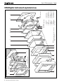
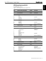
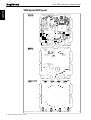
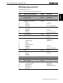
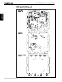
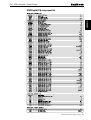
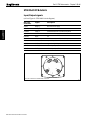
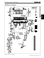
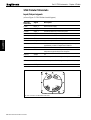
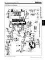
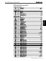
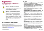
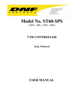
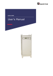
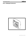
Part 1. ST60 Instruments – Digital
Part 1. ST60 Digital instruments
D4468-2
ST60 Instruments Service Manual 83142-1 i
Part 1. ST60 Instruments – Digital
Contents
ST60 Digital instrument exploded view ............................................................................ iv
Chapter 1. ST60 Speed instrument ................................................................................... 1
Disassembly/reassembly ............................................................................................ 1
Self-test procedure ...................................................................................................... 1
Self test stage 1 ................................................................................................. 1
Self-test stage 2 ................................................................................................. 1
Self-test stage 4 ................................................................................................. 2
ST60 Speed spare parts list .......................................................................................... 3
ST60 Speed PCB details ............................................................................................. 4
Input/Output signals .......................................................................................... 4
ST60 Speed circuit diagram ............................................................................... 5
ST60 Speed PCB layout ............................................................................................. 6
ST60 Speed PCB component list ....................................................................... 7
Chapter 2. ST60 Depth instrument ................................................................................... 9
Disassembly/reassembly ............................................................................................ 9
Self-test procedure ...................................................................................................... 9
Self test stage 1 ................................................................................................. 9
Self-test stage 2 ................................................................................................. 9
Self-test stage 4 ............................................................................................... 10
ST60 Depth spare parts list ........................................................................................ 11
ST60 Depth PCB details ........................................................................................... 12
Input/Output signals ........................................................................................ 12
ST60 Depth circuit diagram ............................................................................. 13
ST60 Depth PCB layout ........................................................................................... 14
ST60 Depth PCB component list ..................................................................... 15
Chapter 3. ST60 Multi instrument .................................................................................. 17
Disassembly/reassembly .......................................................................................... 17
Self-test procedure .................................................................................................... 17
Self test stage 1 ............................................................................................... 17
Self-test stage 2 ............................................................................................... 17
NMEA I/O Testing .......................................................................................... 18
ST60 Multi spare parts list ......................................................................................... 19
ST60 Multi PCB details ............................................................................................ 20
Input/Output signals ........................................................................................ 20
ST60 Multi circuit diagram .............................................................................. 21
ST60 Multi PCB layout ............................................................................................ 22
ST60 Multi PCB component list ...................................................................... 23
ii ST60 Instruments Service Manual 83142-1
Part 1. ST60 Instruments – Digital
Chapter 4. ST60 Tridata instrument ............................................................................... 25
Disassembly/reassembly .......................................................................................... 25
Self-test procedure .................................................................................................... 25
Self test stage 1 ............................................................................................... 25
Self-test stage 2 ............................................................................................... 25
Self-test stage 4 ............................................................................................... 26
ST60 Tridata spare parts list ...................................................................................... 27
ST60 Tridata PCB details .......................................................................................... 28
Input/Output signals ........................................................................................ 28
ST60 Tridata circuit diagram ........................................................................... 29
ST60 Tridata PCB layout .......................................................................................... 30
ST60 Tridata PCB component list .................................................................... 31
ST60 Instruments Service Manual 83142-1
iii
16
Figure 1: ST60 Speed, Depth, Multi and Tridata Digital Instrument exploded view
iv ST60 Instruments Service Manual 83142-1
1
2 Assembly
Flush mounting
2
17(x4)
Torque 0.33Nm (3lb in)
18
3
19
4
5
6
7
9
10 (Note A)
1. Facia bezel
2. Keypad
3. Facia
4. Inner keypad
5. Label
6. LCD display
7. Diffuser
8. Reflector
9. PCB assembly
10. Case seal
12 13(x3)
(x3) Torque 0.22Nm(2lbin)
11
A. It is recommended that a new case seal (10)
is fitted on re-assembly.
Note:
8
14
11. Rear case
12. Washer (x3)
13. Screw (x11)
14. Label (rear case)
15. Gasket
16. Flush mount bezel
17. Screw (x4)
18. Flush mount seal
19. Rear bracket
13(x8)
Torque 0.22Nm(2lbin)
15
D4448-1
Part 1. ST60 Instruments – Digital
ST60 Digital instrument exploded view
Chapter 1. ST60 Speed instrument
Disassembly/reassembly
On reassembly (refer to Figure 1), it is important that the PCB assembly module is
fixed to the facia (3) using a torque of 0.22Nm (2lb in). Similarly, fixing the rear case
(11) to the facia (3) must also be torqued to 0.22Nm (2lb in).
Note: Failure to practice using the recommended torques may result in damage to
the facia inserts. It is also recommended a new case seal (10) is fitted on reassembly.
Self-test procedure
The ST60 Speed instrument has built-in self-test functions to aid fault diagnosis.
To access self-test mode, press Key 1 and Key 4 together for 4 seconds. When the
unit beeps, immediately press Key 3 and Key 4 together momentarily. The unit will
enter self-test stage 1.
Self test stage 1
A. The unit should display “TEST1”
B. Audible Beep for 1 second.
C. There will be a SeaTalk transmission to check the transmit/receive circuits.
D. The EEPROM is tested.
The following failure codes may be generated:
Message
Failure Mode
Action
FAIL 1
SeaTalk Rx/Tx
Check for damaged bucket connectors/rear-case pins.
Check SeaTalk interface components around TR1, TR2and TR3.
FAIL 2
EEPROM failure
Replace EEPROM (IC2)
If there is no audible beep, check TR11 and RN3 and the buzzer for damage. If the
beep is quiet, check R21.
If all test pass, “PASS” is shown on the display. Press Key 1 and Key 2 together
momentarily to progress to self-test stage 2.
Self-test stage 2
A. The unit should display “TEST 2” for 1 second.
B. Illumination will change between level 0 and level 3 every second.
C. Any key press sound cause audible beep.
D. LCD segments will cycle through the following sequence:
1
2
3
4
D4479-1
ST60 Instruments Service Manual 83142-1 1
A22001
Part 1. ST60 Instruments – Chapter 1. Speed
A22001
Part 1. ST60 Instruments – Chapter 1. Speed
No fail codes are generated since stage 2 is an audio/visual check. The following can,
however, be used as a guide to isolate a problem:
Failure Mode
Action
No illumination
Check TR14, TR13, TR15 and associated components.
Check all LEDs.
Keypad Illumination failure
(LCD illumination will also be degraded)
Check TR14, TR13, R22 and R23.
Check LED1-6 for open circuit.
Keypad illumination OK
but degraded LCD illumination
Check TR14, TR15, RN3, R24.
Check LED 7 and 8 for open circuit.
No beep when key pressed
Replace keyswitch.
LCD segment(s) missing completely
Check LCD solder pins for poor/dry joints.
Check IC3 for unsoldered pins.
Faint LCD segments
Check LCD pins for shorts.
Check IC3 for shorts.
Press Key 1 and Key 2 together momentarily to progress to self-test stage 4 (stage 3
not supported on this instrument).
Self-test stage 4
Note: A known good transducer must be connected for this test.
A. The unit should display ‘TEST 4’ for 1 second.
B. Transducer test is performed.
Spin the paddle wheel within 15 seconds of entering this test. If the interface is
working correctly, “PASS” will be shown. Otherwise “FAIL 10” is shown.
If the test fails, do the following:
Check
Failure Mode
Action
Voltage at 12V_SPD
No voltage or low voltage (<11.0)
with 12V battery supply.
Check TR17, TR20, R63 and R64.
L7
Open circuit
Replace L7
D3
Open circuit
Replace D3
Voltage at TEMP pin
Outside acceptable range of
0.76 to 1.00V (18 - 25 degrees C)
Check L9 for open circuit
Check R14
AVREF
Outside acceptable range of
2.5V +/- 0.25v
Check TR4.
Check R74, 17
Press Key 1 and Key 2 together momentarily to exit self-test.
2 ST60 Instruments Service Manual 83142-1
Part 1. ST60 Instruments – Chapter 1. Speed
A22001
ST60 Speed spare parts list
The item numbers refer to
Figure 1: ST60 Digital instrument exploded view
Item
Spare/Accessory Description
Part No.
1
Facia bezel
A25001
–
Suncover, standard
A25004
Not illustrated
2
Keypad, Speed
A28019
Pack of 5
Facia with case seal, including
Facia
Case seal
Washer (x3)
Screw (x11)
A28013
3
10
12
13
Inner keypad, including
Inner keypad
Case seal
Washer (x3)
Screw (x11)
A28022
4
10
12
13
5
Display label, Speed
A28031
Pack of 5
6
LCD display, Speed
A28023
Also serves the Depth
or Multi
PCB assembly, Speed, including
A28010
Assembled module consisting
of items 6, 7, 8, 9.
See A28023
6
7
8
9
10
12
13
Comments
See A28027
Torque to 0.22Nm (2lb in)
See A28027
Torque to 0.22Nm (2lb in)
LCD display, Speed
Diffuser
Reflector
PCB assembly, Speed
Case seal
Washer (x3)
Screw (x11)
See A28027
Torque to 0.22Nm (2lb in)
10
Case seal
A28027
Pack of 5
Rear case assembly, including
Case seal
Rear case
Screw (x8)
A28014
10
11
13
14
Label, Speed (rear case)
A28035
Pack of 5
15
Gasket
A28028
Pack of 5
16
Flush mount bezel
A25002
Flush mount kit, including
Suncover, flush mount
Flush mount bezel
Screw (x4)
Flush mount seal
Rear bracket
A25003
–
16
17
18
19
See A28027
Torque to 0.22Nm (2lb in)
Not illustrated
See A25002
Torque to 0.33Nm (3lb in)
ST60 Instruments Service Manual 83142-1 3
ST60 Speed PCB details
Input/Output signals
(refer to Figure 2. ST60 Speed circuit diagram)
Rear case
connection
Signal
Description
A (Red)
BATT+_2
Nominal 12V DC supply
B (Screen)
BATT-_2
OV
C (Yellow)
STALK_2
Intermittent streams of (nominal) 12V pulses
D (Red)
BATT+
Nominal 12V DC supply
E (Screen)
BATT-
OV
F (Yellow)
STALK
Intermittent streams of (nominal) 12V pulses
G (Red)
12V_SPD
Approximately 11.2V DC out
H (Green)
SPD
With transducer attached, spinning paddle-wheel produces pulses
approximately 11.2V DC in amplitude @ 5.5Hz/Knot.
J (Screen)
OV
OV
K (White)
TEMP
With transducer attached, voltage here is dependant on
temperature. Approximately 1.8v at 0 degrees C.
L (Brown)
OVANA
OV
A
B
CD E
F
G
A22001
Part 1. ST60 Instruments – Chapter 1. Speed
DE
PT
J
L K
H
Rear case connections to ST60 Speed instrument
4 ST60 Instruments Service Manual 83142-1
H
SPE
ED
D4480-1
Part 1. ST60 Instruments – Chapter 1. Speed
D4453-1
A22001
ST60 Speed circuit diagram
Figure 2. ST60 Speed circuit diagram
ST60 Instruments Service Manual 83142-1 5
A22001
Part 1. ST60 Instruments – Chapter 1. Speed
ST60 Speed PCB layout
Taken from Drawing No: 4315-004 Issue: D Date: 01-10-98
6 ST60 Instruments Service Manual 83142-1
D4451-1
ST60 Speed PCB component list
ST60 SPEED Digital
Taken from Drawing No: 4315-004 Issue: D Date: 01-10-98
D4452-1
ST60 Instruments Service Manual 83142-1 7
A22001
Part 1. ST60 Instruments – Chapter 1. Speed
A22001
Part 1. ST60 Instruments – Chapter 1. Speed
8 ST60 Instruments Service Manual 83142-1
Part 1. ST60 Instruments – Chapter 2. Depth
Chapter 2. ST60 Depth instrument
On reassembly (refer to Figure 1), it is important that the PCB assembly module is
fixed to the facia (3) using a torque of 0.22Nm (2lb in). Similarly, fixing the rear case
(11) to the facia (3) must also be torqued to 0.22Nm (2lb in).
Note: Failure to practice using the recommended torques may result in damage to
the facia inserts. It is also recommended a new case seal (10) is fitted on reassembly.
Self-test procedure
The ST60 Depth instrument has built-in self-test functions to aid fault diagnosis.
To access self-test mode, press Key 1 and Key 4 together for 4 seconds. When the
unit beeps, immediately press Key 3 and Key 4 together momentarily. The unit will
enter self-test stage 1.
Self test stage 1
A. The unit should display “TEST 1”
B. Audible Beep for 1 second.
C. There will be a SeaTalk transmission to check the transmit/receive circuits.
D. The EEPROM is tested.
The following failure codes may be generated:
Message
Failure Mode
Action
FAIL 1
SeaTalk Rx/Tx
Check for damaged bucket connectors/rear-case pins.
Check SeaTalk interface components around TR1, TR2and TR3.
FAIL 2
EEPROM failure
Replace EEPROM (IC2).
If there is no audible beep, check TR11 and RN3 and the buzzer for damage. If the
beep is quiet, check R21.
If all test pass, “PASS” is shown on the display. Press Key 1 and Key 2 together
momentarily to progress to self-test stage 2.
Self-test stage 2
A. The unit should display “TEST 2” for 1 second.
B. Illumination will change between level 0 and level 3 every second.
C. Any key press sound cause audible beep.
D. LCD segments will cycle through the following sequence:
1
2
3
4
D4479-1
ST60 Instruments Service Manual 83142-1 9
A22002
Disassembly/reassembly
Part 1. ST60 Instruments – Chapter 2. Depth
A22002
No fail codes are generated since stage 2 is an audio/visual check. The following can,
however, be used as a guide to isolate a problem:
Failure Mode
Action
No illumination
Check TR14, TR13, TR15 and associated components.
Check all LEDs.
Keypad Illumination failure
(LCD illumination will also be degraded)
Check TR14, TR13, R22 and R23.
Check LED1-6 for open circuit.
Keypad illumination OK
but degraded LCD illumination
Check TR14, TR15, RN3, R24.
Check LED 7 and 8 for open circuit.
No beep when key pressed
Replace keyswitch.
LCD segment(s) missing completely
Check LCD solder pins for poor/dry joints.
Check IC3 for unsoldered pins.
Faint LCD segments
Check LCD pins for shorts.
Check IC3 for shorts.
Press Key 1 and Key 2 together momentarily to progress to self-test stage 4 (stage 3
not supported on this instrument).
Self-test stage 4
Note: For this test, a known good transducer must be connected and placed in water
where an echo can be detected. Alternatively, and echo simulator can be used.
A. The unit should display “TEST 4” for 1 second.
B. Transducer test is performed.
If the interface is working correctly, “PASS” will be shown within 15 seconds.
Otherwise “FAIL 8” is shown.
If the test fails, do the following:
Check
Failure Mode
Action
Pulses at pins 8 and 10 of IC4
No pulses
Check R68, 76, 77.
Check IC4 and IC5 and replace if suspect (trace
pulses from IC3).
Pulses at drain of TR5
No pulses
Check L5 and R19 for open circuit.
Replace TR5.
Replace T1.
Pulses at drain of TR6
No pulses
Check L5 and R19 for open circuit.
Replace TR6.
Replace T1.
Pulses at DEPTH+ and DEPTH-
No pulses
Check C11 and C12 for open circuit.
Replace T1
Depth receiver output pulses
at pin 11 of IC5
No pulses
Fault diagnosis of the depth receiver circuit
requires specialist knowledge and the units
should be returned to Raytheon Marine Ltd.
Press Key 1 and Key 2 together momentarily to exit self-test.
10 ST60 Instruments Service Manual 83142-1
Part 1. ST60 Instruments – Chapter 2. Depth
ST60 Depth spare parts list
The item numbers refer to
Figure 1: ST60 Digital instrument exploded view
Spare/Accessory Description
Part No.
1
Facia bezel
A25001
–
Suncover,standard
A25004
Not illustrated
2
Keypad, Depth
A28019
Pack of 5
Facia with case seal, including
Facia
Case seal
Washer (x3)
Screw (x11)
A28013
3
10
12
13
Inner keypad, including
Inner keypad
Case seal
Washer (x3)
Screw (x11)
A28022
4
10
12
13
5
Display label, Depth
A28030
Pack of 5
6
LCD display, Depth
A28023
Also serves the Speed
or Multi
PCB assembly, Depth, including
A28009
Assembled module consisting
of items 6, 7, 8, 9.
See A28023
6
7
8
9
10
12
13
Comments
See A28027
Torque to 0.22Nm (2lb in)
See A28027
Torque to 0.22Nm (2lb in)
LCD display, Depth
Diffuser
Reflector
PCB assembly, Depth
Case seal
Washer (x3)
Screw (x11)
See A28027
Torque to 0.22Nm (2lb in)
10
Case seal
A28027
Pack of 5
Rear case assembly, including
Case seal
Rear case
Screw (x8)
A28014
10
11
13
14
Label, Depth (rear case)
A28036
Pack of 5
15
Gasket
A28028
Pack of 5
16
Flush mount bezel
A25002
A25003
–
16
17
18
19
Flush mount kit, including
Suncover, flush mount
Flush mount bezel
Screw (x4)
Flush mount seal
Rear bracket
See A28027
Not illustrated
See A25002
Torque to 0.33Nm (3lb in)
ST60 Instruments Service Manual 83142-1 11
A22002
Item
Part 1. ST60 Instruments – Chapter 2. Depth
ST60 Depth PCB details
Input/Output signals
A22002
(refer to Figure 3. ST60 Depth circuit diagram)
Rear case
connection
Signal
Description
A (Red)
BATT+_2
Nominal 12V DC supply
B (Screen)
BATT-_2
OV
C (Yellow)
STALK_2
Intermittent streams of (nominal) 12V pulses
D (Red)
BATT+
Nominal 12V DC supply
E (Screen)
BATT-
OV
F (Yellow)
STALK
Intermittent streams of (nominal) 12V pulses
G (Black)
DEPTH-
Intermittent pulses of 200KHz, approximately 400us wide, 300Vp-p
H (Blue)
DEPTH+
Intermittent pulses of 200KHz, approximately 400us wide, 300Vp-p
J (Screen)
DEPTH_GND
OV
A
B
CD E
F
G
H
DE
PT
H
Rear case connections to ST60 Depth instrument
12 ST60 Instruments Service Manual 83142-1
J
SPE
ED
D4481-1
Part 1. ST60 Instruments – Chapter 2. Depth
D4456-1
A22002
ST60 Depth circuit diagram
Figure 3. ST60 Depth circuit diagram
ST60 Instruments Service Manual 83142-1 13
Part 1. ST60 Instruments – Chapter 2. Depth
ST60 Depth PCB layout
A22002
ST60
DEPTH
Digital
Taken from Drawing No: 4316-003 Issue: D Date: 01-10-98
14 ST60 Instruments Service Manual 83142-1
D4454-1
Part 1. ST60 Instruments – Chapter 2. Depth
ST60 Depth PCB component list
A22002
ST60 DEPTH Digital
Taken from Drawing No: 4316-003 Issue: D Date: 01-10-98
D4455-1
ST60 Instruments Service Manual 83142-1 15
A22002
Part 1. ST60 Instruments – Chapter 2. Depth
16 ST60 Instruments Service Manual 83142-1
Part 1. ST60 Instruments – Chapter 3. Multi
Chapter 3. ST60 Multi instrument
Disassembly/reassembly
Self-test procedure
The ST60 Multi instrument has built-in self-test functions to aid fault diagnosis.
To access self-test mode, press Key 1 and Key 4 together for 4 seconds. When the
unit beeps, immediately press Key 3 and Key 4 together momentarily. The unit will
enter self-test stage 1.
Self test stage 1
A. The unit should display “TEST 1”
B. Audible Beep for 1 second.
C. There will be a seatalk transmission to check the transmit/receive circuits.
D. The EEPROM is tested.
The following failure codes may be generated:
Message
Failure Mode
Action
FAIL 1
Seatalk Rx/Tx
Check for damaged bucket connectors/rear-case pins.
Check SeaTalk interface components around TR1, TR2and TR3.
FAIL 2
EEPROM failure
Replace EEPROM (IC2)
If there is no audible beep, check TR11 and RN3 and the buzzer for damage. If the
beep is quiet, check R21.
If all test pass, “PASS” is shown on the display. Press Key 1 and Key 2 together
momentarily to progress to self-test stage 2.
Self-test stage 2
A. The unit should display “TEST 2” for 1 second.
B. Illumination will change between level 0 and level 3 every second.
C. Any key press sound cause audible beep.
D. LCD segments will cycle through the following sequence:
1
2
3
4
D4479-1
ST60 Instruments Service Manual 83142-1 17
A22003
On reassembly (refer to Figure 1), it is important that the PCB assembly module is
fixed to the facia (3) using a torque of 0.22Nm (2lb in). Similarly, fixing the rear case
(11) to the facia (3) must also be torqued to 0.22Nm (2lb in).
Note: Failure to practice using the recommended torques may result in damage to
the facia inserts. It is also recommended a new case seal (10) is fitted on reassembly.
Part 1. ST60 Instruments – Chapter 3. Multi
A22003
No fail codes are generated since stage 2 is an audio/visual check. The following can,
however, be used as a guide to isolate a problem:
Failure Mode
Action
No illumination
Check TR14, TR13, TR15 and associated components.
Check all LEDs.
Keypad Illumination failure
(LCD illumination will also be degraded)
Check TR14, TR13, R22 and R23.
Check LED1-6 for open circuit.
Keypad illumination OK
but degraded LCD illumination
Check TR14, TR15, RN3, R24.
Check LED 7 and 8 for open circuit.
No beep when key pressed
Replace keyswitch.
LCD segment(s) missing completely
Check LCD solder pins for poor/dry joints.
Check IC3 for unsoldered pins.
Faint LCD segments
Check LCD pins for shorts.
Check IC3 for shorts.
Press Key 1 and Key 2 together momentarily to progress to exit self-test (stages 3
and 4 are not supported on this instrument).
NMEA I/O Testing
Note that there is no self-test for NMEA input/output. As a guidline, if NMEA has
failed, do the following:
1. Ensure that NMEA output has been turned ON in user CAL.
2. Ensure that the instrument is receiving seatalk data for translation to NMEA (e.g.
Heading, Latitude, Longitude etc...)
3. Voltage at NMEA_OUT+ should be approx 11.2v with 12v battery supply.
Current supplied from this pin to BATT- should limit at approx.80mA. If there is
a problem with this supply, check TR18, TR19 and associated components.
4. Connect a dummy load (1K resistor) across NMEA_OUT+ and NMEA_OUTand check for pulses at NMEA_OUT- If no pulses are seen, check R18 and TR5.
5. Disconnect dummy load and connect NMEA outputs to corresponding NMEA
inputs. Check for pulses at the junction of R59 and R60 (TP192). If no pulses are
seen, check R55-58, L7 and IC8.
6. Check the final stage output at TR4b (TP116)
18 ST60 Instruments Service Manual 83142-1
Part 1. ST60 Instruments – Chapter 3. Multi
ST60 Multi spare parts list
The item numbers refer to
Figure 1: ST60 Digital instrument exploded view
Spare/Accessory Description
Part No.
1
Facia bezel
A25001
–
Suncover,standard
A25004
Not illustrated
2
Keypad, Multi
A28021
Pack of 5
Facia with case seal, including
Facia
Case seal
Washer (x3)
Screw (x11)
A28013
3
10
12
13
Inner keypad, including
Inner keypad
Case seal
Washer (x3)
Screw (x11)
A28022
4
10
12
13
5
Display label, Multi
A28029
Pack of 5
6
LCD display, Multi
A28023
Also serves the Speed
or Depth
PCB assembly, Multi, including
A28012
Assembled module consisting of items 6, 7, 8, 9.
See A28023
6
7
8
9
10
12
13
Comments
See A28027
Torque to 0.22Nm (2lb in)
See A28027
Torque to 0.22Nm (2lb in)
LCD display, Multi
Diffuser
Reflector
PCB assembly, Multi
Case seal
Washer (x3)
Screw (x11)
See A28027
Torque to 0.22Nm (2lb in)
10
Case seal
A28027
Pack of 5
Rear case assembly, including
Case seal
Rear case
Screw (x8)
A28014
10
11
13
14
Label, Multi (rear case)
A28034
Pack of 5
15
Gasket
A28028
Pack of 5
16
Flush mount bezel
A25002
Flush mount kit, including
Suncover, flush mount
Flush mount bezel
Screw (x4)
Flush mount seal
Rear bracket
A25003
–
16
17
18
19
See A28027
Torque to 0.22Nm (2lb in)
Not illustrated
See A25002
Torque to 0.33Nm (3lb in)
ST60 Instruments Service Manual 83142-1 19
A22003
Item
Part 1. ST60 Instruments – Chapter 3. Multi
ST60 Multi PCB details
Input/Output signals
Rear case
connection
Signal
Description
A (Red)
BATT+_2
Nominal 12V DC supply
B (Screen)
BATT-_2
OV
C (Yellow)
STALK_2
Intermittent streams of (nominal) 12V pulses
D (Red)
BATT+
Nominal 12V DC supply
E (Screen)
BATT-
OV
F (Yellow)
STALK
Intermittent streams of (nominal) 12V pulses
G (Blue)
NMEA_OUT-
Open-drain pull-down
H (Red)
NMEA_OUT+
Approximately 11.2v, current limited to 80mA
J (Blue)
NMEA_IN-
Isolated opto input, 550 ohms
K (Red)
NMEA_IN+
Isolated opto input, 550 ohms
A
G
H
B
CD E
F
K
J
IN
NM
EA
OU
EA
A22003
(refer to Figure 4. ST60 Multi circuit diagram)
T
Rear case connections to ST60 Multi instrument
20 ST60 Instruments Service Manual 83142-1
NM
D4482-1
Part 1. ST60 Instruments – Chapter 3. Multi
Figure 4. ST60 Multi circuit diagram
ST60 Instruments Service Manual 83142-1 21
A22003
D4462-1
ST60 Multi circuit diagram
Part 1. ST60 Instruments – Chapter 3. Multi
ST60 Multi PCB layout
A22003
ST60
MULTI
Digital
Taken from Drawing No: 4321-002 Issue: D Date: 01-10-98
22 ST60 Instruments Service Manual 83142-1
D4460-1
Part 1. ST60 Instruments – Chapter 3. Multi
ST60 Multi PCB component list
A22003
ST60 MULTI Digital
Taken from Drawing No: 4321-002 Issue: D Date: 01-10-98
D4461-1
ST60 Instruments Service Manual 83142-1 23
A22003
Part 1. ST60 Instruments – Chapter 3. Multi
24 ST60 Instruments Service Manual 83142-1
Part 1. ST60 Instruments – Chapter 4. Tridata
Chapter 4. ST60 Tridata instrument
Disassembly/reassembly
On reassembly (refer to Figure 1), it is important that the PCB assembly module is
fixed to the facia (3) using a torque of 0.22Nm (2lb in). Similarly, fixing the rear case
(11) to the facia (3) must also be torqued to 0.22Nm (2lb in).
Note: Failure to practice using the recommended torques may result in damage to
the facia inserts. It is also recommended a new case seal (10) is fitted on reassembly.
Self-test procedure
To access self-test mode, press Key 1 and Key 4 together for 4 seconds. When the
unit beeps, immediately press Key 3 and Key 4 together momentarily. The unit will
enter self-test stage 1.
Self test stage 1
A. The unit should display “TEST 1”
B. Audible Beep for 1 second.
C. There will be a SeaTalk transmission to check the transmit/receive circuits.
D. The EEPROM is tested.
The following failure codes may be generated:
Message
Failure Mode
Action
FAIL 1
SeaTalk Rx/Tx
Check for damaged bucket connectors/rear-case pins.
Check SeaTalk interface components around TR1, TR2and TR3.
FAIL 2
EEPROM failure
Replace EEPROM (IC2)
If there is no audible beep, check TR11 and RN3 and the buzzer for damage. If the
beep is quiet, check R21.
If all test pass, “PASS” is shown on the display. Press Key 1 and Key 2 together
momentarily to progress to self-test stage 2.
Self-test stage 2
A. The unit should display “TEST 2” for 1 second.
B. Illumination will change between level 0 and level 3 every second.
C. Any key press sound cause audible beep.
D. LCD segments will cycle through the following sequence:
1
2
3
4
D4484-1
ST60 Instruments Service Manual 83142-1 25
A22004
The ST60 Tridata instrument has built-in self-test functions to aid fault diagnosis.
Part 1. ST60 Instruments – Chapter 4. Tridata
A22004
No fail codes are generated since stage 2 is an audio/visual check. The following can,
however, be used as a guide to isolate a problem:
Failure Mode
Action
No illumination
Check TR14, TR13, TR15 and associated components. Check all LEDs.
Keypad Illumination failure (LCD
illumination will also be degraded).
Check TR14, TR13, R22 and R23.
Check LED1-6 for open circuit.
Keypad illumination OK
but degraded LCD illumination.
Check TR14, TR15, RN3, R24.
Check LED 7 and 8 for open circuit.
No beep when key pressed.
Replace keyswitch.
LCD segment(s) missing
completely.
Check LCD solder pins for poor/dry joints.
Check IC3 for unsoldered pins.
Faint LCD segments
Check LCD pins for shorts.Check IC3 for shorts.
Press Key 1 and Key 2 together momentarily to progress to self-test stage 4 (stage 3
not supported on this instrument).
Self-test stage 4
Note: A known good speed and depth transducer must be connected for this test.
A. The unit should display ‘TEST 4’ for 1 second.
B. Transducer tests are performed.
Spin the paddle wheel within 15 seconds of entering this test. If there is a problem with
the speed interface “FAIL 10” is shown and the following tests should be carried out.
Check
Failure Mode
Action
Voltage at 12V_SPD
No voltage or low voltage (<11.0)
with 12V battery supply.
Check TR17, TR20, R63 and R64.
L7
Open circuit
Replace L7.
D3
Open circuit
Replace D3.
Voltage at TEMP pin
Outside acceptable range of
0.76 to 1.00V (18 - 25 degrees C)
Check L9 for open circuit.
Check R14.
AVREF
Outside acceptable range of 2.5V +/- 0.25v
Check TR4. Check R74, 17.
Provided the depth transducer is in water where a good echo should be seen, the test
will pass, otherwise “FAIL 8” is shown and the following tests should be carried out:
Check
Failure Mode
Action
Pulses at pins 8 and 10 of IC4
No pulses
Check R68, 76, 77. Check IC4 and IC5 and
replace if suspect (trace pulses from IC3).
Pulses at drain of TR5
No pulses
Check L5 and R19 for open circuit.
Replace TR5. Replace T1.
Pulses at drain of TR6
No pulses
Check L5 and R19 for open circuit.
Replace TR6. Replace T1.
Pulses at DEPTH+ and DEPTH-
No pulses
Check C11 and C12 for open circuit. Replace T1
Depth receiver output pulses
at pin 11 of IC5
No pulses
Fault diagnosis of the depth receiver circuit
requires specialist knowledge and the units
should be returned to Raytheon Marine Ltd.
Press Key 1 and Key 2 together momentarily to exit self-test.
26 ST60 Instruments Service Manual 83142-1
Part 1. ST60 Instruments – Chapter 4. Tridata
ST60 Tridata spare parts list
The item numbers refer to
Figure 1: ST60 Digital Instrument exploded view
Item
Spare/Accessory Description
Part No.
1
Facia bezel
A25001
–
Suncover,standard
A25004
Not illustrated
2
Keypad,Tridata
A28020
Pack of 5
Facia with case seal, including
Facia
Case seal
Washer (x3)
Screw (x11)
A28013
3
10
12
13
Inner keypad, including
Inner keypad
Case seal
Washer (x3)
Screw (x11)
A28022
4
10
12
13
5
Display label,Tridata
A28032
6
LCD display, Tridata
A28024
PCB assembly, Tridata, including
A28011
6
7
8
9
10
12
13
Comments
See A28027
See A28027
Torque to 0.22Nm (2lb in)
LCD display, Tridata
Diffuser
Reflector
PCB assembly, Tridata
Case seal
Washer (x3)
Screw (x11)
Pack of 5
Assembled module consisting of items 6, 7, 8, 9.
See A28024
See A28027
Torque to 0.22Nm (2lb in)
10
Case seal
A28027
Pack of 5
Rear case assembly, including
Case seal
Rear case
Screw (x8)
A28014
10
11
13
14
Label,Tridata (rear case)
A28033
Pack of 5
15
Gasket
A28028
Pack of 5
16
Flush mount bezel
A25002
Flush mount kit, including
Suncover, flush mount
Flush mount bezel
Screw (x4)
Flush mount seal
Rear bracket
A25003
–
16
17
18
19
See A28027
Torque to 0.22Nm (2lb in)
Not illustrated
See A25002
Torque to 0.33Nm (3lb in)
ST60 Instruments Service Manual 83142-1 27
A22004
Torque to 0.22Nm (2lb in)
Part 1. ST60 Instruments – Chapter 4. Tridata
ST60 Tridata PCB details
Input/Output signals
Rear case
connection
Signal
Description
A (Red)
BATT+_2
Nominal 12V DC supply
B (Screen)
BATT-_2
OV
C (Yellow)
STALK_2
Intermittent streams of (nominal) 12V pulses
D (Red)
BATT+
Nominal 12V DC supply
E (Screen)
BATT-
OV
F (Yellow)
STALK
Intermittent streams of (nominal) 12V pulses
G (Red)
12V_SPD
Approximately 11.2V DC out
H (Green)
SPD
With transducer attached, spinning paddle-wheel produces pulses
approximately 11.2V DC in amplitude at 5.5Hz/Knot.
J (Screen)
OV
OV
K (White)
TEMP
With transducer attached, voltage here is dependant on
temperature. Approximately 1.8v at 0 degrees C.
L (Brown)
OVANA
OV
M (Black)
DEPTH-
Intermittent pulses of 200KHz, approximately 400us wide, 300Vp-p
N (Blue)
DEPTH+
Intermittent pulses of 200KHz, approximately 400us wide, 300Vp-p
P (Screen)
DEPTH_GND
OV
A
B
CD E
F
M
N
DE
PT
G
A22004
(refer to Figure 5. ST60 Tridata circuit diagram)
P
H
Rear case connections to ST60 Tridata instrument
28 ST60 Instruments Service Manual 83142-1
J
L K
H
SPE
ED
D4483-1
Part 1. ST60 Instruments – Chapter 4. Tridata
A22004
D4459-1
ST60 Tridata circuit diagram
Figure 5. ST60 Tridata circuit diagram
ST60 Instruments Service Manual 83142-1 29
Part 1. ST60 Instruments – Chapter 4. Tridata
ST60 Tridata PCB layout
A22004
ST60
TRIDATA
Digital
Taken from Drawing No: 4317-002 Issue: E Date: 09-10-98
30 ST60 Instruments Service Manual 83142-1
D4457-1
Part 1. ST60 Instruments – Chapter 4. Tridata
ST60 Tridata PCB component list
A22004
ST60 TRIDATA Digital
Taken from Drawing No: 4317-002 Issue: E Date: 09-10-98
D4458-1
ST60 Instruments Service Manual 83142-1 31
A22004
Part 1. ST60 Instruments – Chapter 4. Tridata
32 ST60 Instruments Service Manual 83142-1