1
Part 3. ST60 Instruments – Transducers
Transducers
Part 3. ST60 Transducers
D4530-1
ST60 Instruments Service Manual 83142-1 i
Part 3. ST60 Instruments – Transducers
Transducers
Contents
Chapter 1. ST60 Speed transducer.................................................................................... 2
Changing a paddlewheel ............................................................................................. 2
Changing the valve assembly ...................................................................................... 3
ST60 Speed transducer spare parts list ......................................................................... 3
Insert assembly installation ......................................................................................... 3
ST60 Speed transducer connections............................................................................. 4
Chapter 2. ST60 Fluxgate compass transducer ................................................................. 6
Functional test ............................................................................................................ 6
Magnetic deviation ..................................................................................................... 6
Disassembly/reassembly ............................................................................................ 6
Fluxgate Compass spare parts list ....................................................................... 7
ST60 Fluxgate Compass transducer connections .......................................................... 7
Chapter 3. ST60 Rudder reference transducer ................................................................. 8
Description ................................................................................................................ 8
Functional Test ........................................................................................................... 8
Balljoint replacement.................................................................................................. 8
ST60 Rudder reference transducer connections ............................................................ 9
Chapter 4. ST60 Wind rotavecta ..................................................................................... 10
Disassembly/reassembly .......................................................................................... 10
Wind rotavecta spare parts list .......................................................................... 10
Wind rotavecta PCB details ....................................................................................... 11
Input/Output signals ........................................................................................ 11
PCB component layout ................................................................................... 11
PCB component list ............................................................................... 11
ST60 Wind Rotavecta connections ............................................................................ 12
Chapter 5. ST60 Windvane transducer ........................................................................... 14
Disassembly/reassembly .......................................................................................... 14
Windvane (standard arm) spare parts lists ......................................................... 15
Long arm masthead transducer ........................................................................ 15
Functional test .......................................................................................................... 15
Windvane head PCB details ...................................................................................... 16
Input/Output signals ........................................................................................ 16
PCB component layout ................................................................................... 16
PCB component list ............................................................................... 16
Anemometer head PCB details .................................................................................. 17
Input/Output signals ........................................................................................ 17
PCB component layout ................................................................................... 17
PCB component list ............................................................................... 17
ST60 Windvane connections ..................................................................................... 18
ii ST60 Instruments Service Manual 83142-1
Transducers
Part 3. ST60 Instruments – Transducers
This page is
intentionally
left blank
ST60 Instruments Service Manual 83142-1 1
Part 3. ST60 Instruments – Transducers
Transducers
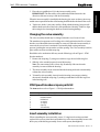
Chapter 1. ST60 Speed transducer
HAND
T
Insert (top view)
HTEN
IG
Arrow indicates
front of boat
Insert (side view)
Pull ring
Cap nut
3, 'O' ring
Key
4, 'O' ring
('O' rings should be
free of abrasions,
knicks, and cuts to
ensure watertight
entegrity.)
1, Paddlewheel shaft
Flat area of blade
faces front of boat
Housing (side view)
2, Paddlewheel
5, Snap ring
Keyway
Vane housing
(6, valve assembly)
Vane retainer pin
(6, valve assembly)
Vane
(6, valve assembly)
Spring
(6, valve assembly)
Hull
Arrow indicates
front of boat
D4518-1
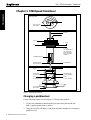
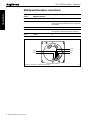
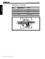
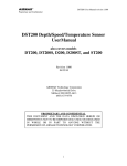
Figure 1: ST60 Speed transducer
Changing a paddlewheel
For the following sequence refer to Figure 1: ST60 Speed transducer.
1. Use the new paddlewheel shaft from the spare parts kit to push out the old
shaft (1) approximately 5mm (1/4inch).
2. Grasp the end of the old shaft (1) with pliers and pull it straight out, releasing the
paddlewheel (2).
2 ST60 Instruments Service Manual 83142-1
3. Place the new paddlewheel (2) in the insert assembly cavity.
IMPORTANT: The flat surface of the paddewheel blades must face the
direction of the arrow on top of the insert assembly.
When the insert assembly is installed in the housing, the arrow on the top insert cap
and the water exposed flat surface of the housing should both face the front of the vessel.
4. Tap the new shaft (1) into place until it is flush with the housing, being careful
that the shaft enters the centre hole of the paddlewheel bearing. Failure to align
the bearing before inserting the shaft can result in bearing damage.
Changing the valve assembly
The valve assembly should only be changed when the vessel is out of water.
The transducer incorporates a self-sealing valve which minimizes the flow of water
into the vessel should the insert assembly be removed. When the insert assembly is
removed, the curved vane is activated is activated by both a spring and water
pressure, pushing the vane upward to seal the opening. The valve assembly is held in
place with a corrosion resistant snap ring.
Should the valve mechanism fail carry out the following (refer to Figure 1: ST60
Speed transducer).
1. Remove the snap ring (5), using a screwdriver to pry the end of the ring free.
2. Slide the valve assembly upward, out of the housing.
Note: The vane retainer pin is a loose slip-fit and may slide out when the
assembly is removed from the housing.
3. The insert assembly can be reinserted into the housing and used conventionally,
without the valve assembly.
4. To install a valve assembly, insert it into the housing (vane tongue pointing
downward). Install the snap ring (5), making certain that it locks into its groove
in the housing wall.
ST60 Speed transducer spare parts list
The item numbers refer to Figure 1: ST60 Speed transducer
Item
Spare/Accessory Description
Part No.
Speed transducer service kit, including
Paddlewheel shaft
Paddlewheel
‘O’ ring (x2)
‘O’ ring (x2)
Snap ring
Valve assembly
D234
1
2
3
4
5
6
Comments
Insert assembly installation
When reinstalling the insert assembly, ensure ‘O’ rings have been inspected and
replaced if necesssary, then lubricated and the key of the insert assembly locates with
the keyway of the housing assembly. Secure with cap nut (hand tighten).
ST60 Instruments Service Manual 83142-1 3
Transducers
Part 3. ST60 Instruments – Transducers
Part 3. ST60 Instruments – Transducers
Transducers
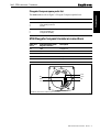
ST60 Speed transducer connections
Cable core
colour
Instrument head circuit
diagram reference
Description
Red
12V_SPD
Approximately 11.2V DC out
Green
SPD
With transducer attached, spinning paddle-wheel
produces pulses approximately 11.2V DC in amplitude
at 5.5Hz/Knot.
Screen
OV
OV
White
TEMP
With transducer attached, voltage here is dependant
on temperature. Approximately 1.8v at 0 degrees C.
Brown
OVANA
OV
Screen
White
Green
Brown
Red
DE
PT
H
Transducer connections to ST60 Speed instrument
4 ST60 Instruments Service Manual 83142-1
SPE
ED
D4481-2
Transducers
Part 3. ST60 Instruments – Transducers
This page is
intentionally
left blank
ST60 Instruments Service Manual 83142-1 5
Part 3. ST60 Instruments – Transducers
Transducers
Chapter 2. ST60 Fluxgate compass transducer
Functional test
Disconnect the Fluxgate from the Autopilot and check continuity as follows:
Cable colour
Resistance
Screen to blue
< 10 ohms
Red to green
< 5 ohms
Red to yellow
< 5 ohms
Red to screen
Open circuit
Magnetic deviation
The Fluxgate Compass requires careful siting if optimum Autopilot performance is
to be acheived. The SeaTalk electronics is able to correct the compass for most
deviating magnetic fields present when the linearisation procedure is carried out.
Any further deviation, introduced after linearisation, will introduce an error between
the Fluxgate and the ship’s compass. This can be removed by carrying out the
linearisation again. If the displayed deviation is greater than +/– 15 degrees the
Fluxgate should be resited.
Note: The linearisation procedure should always be carried out if the Fluxgate has
been exchanged, removed or moved from its original mounting position.
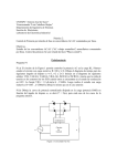
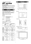
Disassembly/reassembly
7
8
Connector Wiring Detail
Screen
Blue
Green
Red
Yellow
Hot melt glue
Cable tie
9
3
4
6
1. Cover
2. Seal
3. Pivot retaining screw (x2)
4. Bracket
5. Pivot sub-assembly
1
5
6. Fluxgate sub-assembly
7. Body
8. Body screw (x4)
9. Cable
2
D4519-1
Figure 2: Fluxgate Compass exploded view
6 ST60 Instruments Service Manual 83142-1
Part 3. ST60 Instruments – Transducers
Fluxgate Compass spare parts list
Item
Spare Description
Part No.
Compass base kit, including
Pivot retaining screw (x2)
Bracket
M096
3
4
Fluxgate sub-assembly, including
Pivot sub-assembly (x2)
Fluxgate sub-assembly
M022
5
6
Transducers
The item numbers refer to Figure 2: Fluxgate Compass exploded view
Comments
ST60 Fluxgate Compass transducer connections
Cable core
colour
Instrument head circuit
diagram reference
Description
Red
VREF
Fluxgate 2.5V
Yellow
FGA
Sense A
Green
FGB
Sense B
Blue
FGDRV
Fluxgate drive
White
Screen
Fluxgate OV return
Green
Blue
Yellow
White
(screen)
Red
RO
TA
COM
Transducer connections to ST60 Compass instrument
S
PA
S
D4488-2
ST60 Instruments Service Manual 83142-1 7
Part 3. ST60 Instruments – Transducers
Transducers
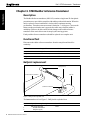
Chapter 3. ST60 Rudder reference transducer
Description
The Rudder Reference transducer (M81105) contains a single-turn 5k ohm plastic
potentiometer to provide the autopilot with rudder position information. When the
unit is replaced, correct installation is vital to achieve optimum steering
performance. Transducer arm movement is limited to +/- 60 degrees. Care must be
taken to make sure that the arm is opposite the cable entry when the rudder is
amidships. Failure to do this could result in damage to the rudder reference
transducer if the arm is driven onto its stops by the steering system.
Faulty rudder reference transducers should be replaced as a complete unit.
Functional Test
Disconnect the rudder reference transducer from the autopilot and check for
continuity.
Cable colour
Arm position
Resistance
Green/red
Any position
5k ohm +/- 5%
Blue/green
Anti clockwise stop
1.66k ohm +/- 10%
Blue/green
Clockwise stop
3.3k ohm +/- 10%
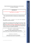
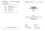
Balljoint replacement
2, Ball joint cap
Rudder reference transducer
Tiller arm
1, Rudder mounted ball
D4520-1
Figure 3: Balljoint kit exploded view
The item numbers refer to Figure 3: Ball joint kit exploded view
Item
Spare/Accessory Description
Part No.
Ball joint kit, including
Rudder mounted ball
Ball joint cap (x2)
D143
1
2
8 ST60 Instruments Service Manual 83142-1
Comments
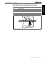
Part 3. ST60 Instruments – Transducers
Cable core
colour
Instrument head circuit
diagram reference
Description
Red
5V
Transducer +V supply
Blue
VRUD
Transducer output
Green
OV
Transducer 0V return
White
Screen
Transducer screen
Transducers
ST60 Rudder reference transducer connections
Green
Blue
White
(screen)
Red
RO
R
TA
RU
Transducer connections to ST60 Rudder instrument
DD
E
D4489-2
ST60 Instruments Service Manual 83142-1 9
Part 3. ST60 Instruments – Transducers
Transducers
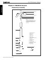
Chapter 4. ST60 Wind rotavecta
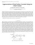
Disassembly/reassembly
1 (Note A)
2
3 (Note A)
4
5
Note:
A. Unscrew the Allen grubsrew (1)
sufficiently to allow the Rotavecta cups (2)
to be pulled off the shaft. If the screw is
backed off too far, the captive nut (3)
can fall out.
6
7
8
9
1. Allen grubscrew M3
2. Rotavecta cups
3. Captive nut
4. Rotavecta pod
5. Pod 'O' ring
6. Rotavecta body
7. Mounting pod screw M5 (x2)
8. Base plate
9. Base plate locknut
10. Cover plate
11. Connecting cable
12. Mounting pod cover plate
13. Mounting pod
14. Grubscrew M5
10
12
11
13
14
D4046-2
Figure 4: Wind rotavecta exploded view
10 ST60 Instruments Service Manual 83142-1
Part 3. ST60 Instruments – Transducers
Wind rotavecta spare parts list
Item
Spare/Accessory Description
Part No.
Rotavecta transducer kit, including
Allen grubscrew M3
Rotavecta cups
Captive nut M3
D240
1
2
3
Q113
4
5
Rotavecta pod assembly, including
Rotavecta pod
Pod ‘O’ ring
Rail mounting kit, including
Mounting pod screw M5(x2)
Base plate
Base plate locknut
Cover plate
Connecting cable
Mounting pod cover plate
Mounting pod
Grubscrew M5
D316
7
8
9
10
11
12
13
14
Transducers
The item numbers refer to Figure 4: Wind rotavecta exploded view
Comments
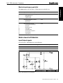
Wind rotavecta PCB details
Input/Output signals
(refer to Figure 5: Wind Rotavecta circuit diagram)
Cable core colour
Transducer circuit diagram reference
Description
Red
P1
Current source
Blue
P2
0V
D4050-2
Figure 5: Wind Rotavecta circuit diagram
ST60 Instruments Service Manual 83142-1 11
Part 3. ST60 Instruments – Transducers
Transducers
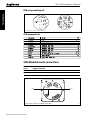
PCB component layout
Taken from Drawing No: 4233-001 Issue: C Date: 08.11.93
D4048-2
PCB component list
D4049-2
Taken from Drawing No: 4233-001 Issue: C Date: 08.11.93
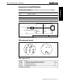
ST60 Wind Rotavecta connections
Cable core
colour
Instrument head circuit
diagram reference
Description
Red
ROTA+
Rotavecta current constant
Blue
ROTA–
Rotavecta 0V
Red
Blue
RO
TA
N
VA
Wind rotavecta connections to ST60 Wind instrument
12 ST60 Instruments Service Manual 83142-1
E
D4486-2
Transducers
Part 3. ST60 Instruments – Transducers
This page is
intentionally
left blank
ST60 Instruments Service Manual 83142-1 13
Part 3. ST60 Instruments – Transducers
Transducers
Chapter 5. ST60 Windvane transducer
Disassembly/reassembly
1
The ST60 Masthead Mount (9) comes with
fitted spades in the ST60 Wind System
A22012, but as a spare the ST50 Masthead
Mount (Q024) may be supplied which is fitted
wih a connector. This connector is cut off, the
outer sheathing stripped and spades crimped
onto the cable wires.
2
3
4
(Note A)
5
Use sleeves from replaced
standard arm assembly.
Sleeves do not come as a spare.
6
Use sleeves from replaced
standard arm assembly.
Sleeves do not come as a spare.
7
9
Note:
A. Unscrew the Grubscrew (2) sufficiently
to allow the Windvane (1) to be pulled off
the shaft. If the screw is backed off too
far, the nut (4) can fall out.
8
2
1.
2.
3.
4.
5.
6.
7.
8.
9.
Windvane
Grubscrew (x2)
Balance weight
Nut, M3
Upper (windvane) pod
Masthead transducer arm assembly
Lower (anemometer) pod
Anemometer head
ST60 Masthead mount
D4521-1
Figure 6: ST60 Windvane exploded view
14 ST60 Instruments Service Manual 83142-1
Part 3. ST60 Instruments – Transducers
The item numbers refer to Figure 6: Windvane exploded view
Item
Spare/Accessory Description
Part No.
Comments
Masthead transducer service kit, including
Windvane
Grubscrew, M3 (x2)
Balance weight
Nut, M3
Anemometer head
D139
1
2
3
4
8
5
Upper (windvane) pod
Q001
6
Masthead transducer arm assembly
Q025
7
Lower (anemometer) pod
Q002
9
Masthead mount assembly
Q024
30 metres of cable.
May be supplied with a
connector. This connector is
cut off, sheathing stripped and
spades crimped onto the
cable wires.
Masthead tansducer
D168
Mashead mount assembly
not supplied
Standard arm
Also available is the ST60 Wind Masthead Mount incorporating 50 metres of cable
(A28042).
Long arm masthead transducer
On the Long Arm Masthead Transducer Unit (D225) the masthead arm (carbon
fibre) assembly is not available as a spare.
Functional test
The operation of the Masthead Mounted Windvane can be checked using the
following procedure:
1. Connect +8V dc to the red core and 0V to the screen.
2. Connect a digital volt meter across the screen and the green core.
3. Rotate vane head through 360 degrees and check that the meter reading
oscillates sinusoidally. The maximum reading must be between 6V and 5.5V.
The minimum reading must be between 2V and 2.5V.
4. Repeat section 3 with the meter connected across the blue core and screen.
The anemometer transducer can not easily be tested and a replacement pod should
be fitted if suspected to be faulty.
ST60 Instruments Service Manual 83142-1 15
Transducers
Windvane (standard arm) spare parts lists
Part 3. ST60 Instruments – Transducers
Transducers
Windvane head PCB details
Input/Output signals (refer to Figure 7: Windvane head circuit diagram)
Cable core
colour
Transducer circuit
diagram reference
Description
Red
P1
8V supply
Green
P2
Sin output
Blue
P3
Cos output
Black
P4
0V supply
Vsupply
P1
D1
BYV27
IC1
+
P2
Vsine
D2
BYV27
P3
D3
BYV27
Vcosine
P4
D4
BYV27
0/P
SS94AI
--
IC2
+
0/P
SS94AI
--
0V
D4524-1
TITLE: WIND VANE CIRCUIT DIAGRAM
DRWG No: 3015-036-B
Figure 7: Windvane head circuit diagram
PCB component layout
Taken from Drawing No: 4060-001 Issue: A
D4525-1
PCB component list
24010
04047
02038
3015-036
PIN
ANALOGUE POSITION SENSOR SS94A1 HONEYWELL
DIODE (FAST RECOVERY) BYV27-100 MULLARD
WINDVANE PCB
Taken from Drawing No: 4060-001 Issue: A
16 ST60 Instruments Service Manual 83142-1
IC1, IC2
D1, D2, D3, D4
D4526-1
Part 3. ST60 Instruments – Transducers
Anemometer head PCB details
Cable core
colour
Transducer circuit
diagram reference
Description
Red
P1
8V supply
Yellow
P2
Anemometer output
Black
P3
0V supply
D1
BYV27
P2
R1
Anemometer
Transducers
Input/Output signals (refer to Figure 8: Anemometer head circuit diagram)
+
IC1
0/P
--
P1
Vsupply
ZD1
BZV8512
P3
D2
BYV27
0V
D4527-1
TITLE: ANEMOMETER CIRCUIT DIAGRAM
DRWG No: 3015-037-C
Figure 8: Anemometer head circuit diagram
PCB component layout
Taken from Drawing No: 4060-002 Issue: D
D4528-1
PCB component list
24010
04046
02038
02040
01108
3015-037
PIN
ANALOGUE POSITION SENSOR SS41 HONEYWELL
DIODE (FAST RECOVERY) BYV27-100 MULLARD
ZENER DIODE BZV85C12
RESISTOR 1K5 10% 0.125W
PCB DETAIL
Taken from Drawing No: 4060-002 Issue: D
IC1
D1, D2
Z1
R1
D4529-1
ST60 Instruments Service Manual 83142-1 17
Part 3. ST60 Instruments – Transducers
Transducers
ST60 Windvane connections
Cable
colour core
Instrument head circuit
diagram reference
Description
Red
8V
Vane supply
Green
SIN
sin output
Blue
COS
cos output
Yellow
ANN
annemometer
White
SCREEN
Transducer OV return
Blue
Green
Yellow
Red
White
(screen)
RO
TA
N
VA
Windvane connections to ST60 Wind instrument
18 ST60 Instruments Service Manual 83142-1
E
D4486-3