1
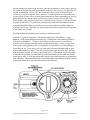
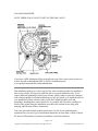
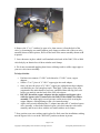
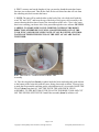
Installing Your Fleck Water Softener
Figuring the amount of gallons to set your water softener meter at!
4 people x 75 gallons per person = 300 gallon used per day. 300 gallons x 15 gpg
hardness = 4500 grains being removed per day. 32,000 grain water softener divided by
4500 grains of hardness = 7.11 days. back off one day for reserves so you still have
treated water for that day until the system regenerates that night = 6 days. 6 days times
water usage of 300 gallons per day = setting meter to regenerate every 1800 gallons of
water that you use.
Note: Your water treatment equipment will only comes with a service manual, showing
you the valve details. Please do not follow the information in that manual, it is written
with the Water Treatment expert in mine, for the purpose of programming the backwash
lengths and salt pound settings etc... We have already set everything on the valve for
you except for two simple things.
1) The amount of gallons you can go before regeneration.
2) The time of day
3) If a SE unit, you would set the calendar override to A-14, this will insure that the
system will not go more than 14 days before it regenerates.
Programming the SE valves:
The chart below is your master programming guide. Remember that all the examples in
this guide are exactly as your valve should read, except for three things that you will
change.
1) Time of day
2) Gallons you will go before regenerating
3) Set calendar override to .A-14, this will insure that the system will not go more than 14
days before it regenerates.
IMPORTANT: In order to get into master programming you need to temporarily set the
time of day to 12:01 PM
Page 1 of 13
Copyright © 2006 Quality Water Treatment, All right reserved.
www.qualitywatertreatment.com
Programming the Econdominder valves:
1) Set time of day
2) Set meter to the gallons you can go before regenerating. To do this follow the
instructions below:
The Fleck 5600, 2510 and 9000 Econdominder is a mechanical metered on demand
valve. There is a dome in the back of the system where the water enters it. Inside the
dome is an impeller coming off the top of the dome is a cable that attaches to the meter
box. When you use water the impeller turns and that turns the cable which turns the meter
Page 2 of 13
Copyright © 2006 Quality Water Treatment, All right reserved.
www.qualitywatertreatment.com
box and counts your water usage that way. Once the set amount of water usage is used up
the system will regenerate itself automatically at the time that you set it for, typically at 2
am and is finished by 3:45 am. The only down fall of this system is when you loose
electricity you need to reset the clock, otherwise it could regenerate at a time when you
are using a lot of water. These systems bypass themselves when regenerating, so you will
pull untreated water into the home and hot water heater if you do not reset the clock.
When sizing a water softener always leave yourself one day of reserves. take the amount
of people in the home x 75 gallons per person per day x that into the hardness of your
water then divide that figure into different sizes of water softeners to figure what size
would be best for you. Typically you want to regenerate no more than every six days and
no less than every 14 days.
Figuring the amount of gallons to set your water softener meter at!
4 people x 75 gallons per person = 300 gallon used per day. 300 gallons x 15 gpg
hardness = 4500 grains being removed per day. 32,000 grain water softener divided by
4500 grains of hardness = 7.11 days. back off one day for reserves so you still have
treated water for that day until the system regenerates that night = 6 days. 6 days times
water usage of 300 gallons per day = setting meter to regenerate every 1800 gallons of
water that you use. To set meter, pull out center clear dial and with other hand on gear
that is behind numbers 0 thru 21, turn dial and clear knob until the white dot is lined up
with the number desired as for above that would be 18 = 1800 gallons. Push center knob
in and turn the gear that your other hand is on until the number 18 the white dot and the
arrow that is at the 11 o'clock position under where it says meter capacity are all lined up
with each other. Then reach behind the valve and plug the cable into the small hole on top
of the dome where the water enters the system water softeners
Page 3 of 13
Copyright © 2006 Quality Water Treatment, All right reserved.
www.qualitywatertreatment.com
2510 AND 9000 METER
NOTE: THERE IS NO CLOCK TO SET ON THE 9000 VALVE.
If you have a KDF Mediaguard Filter to install with your Fleck water system, please see
website for link to Mediaguard KDF 55 AND 85 installation guide.
www.qualitywatertreatment.com/installation.htm
This installation guide gives a basic step by step, start to finish procedure for installing a
basic water softener. All steps provided here are for a typical installation only. If you
require additional plumbing to install your softener, simply contact a person or company
who is knowledgeable in residential plumbing, to help you install, or to install the unit for
you. Installation of these softeners does require basic plumbing skills, tools and
knowledge. Installing these water softeners is very simple and will not be a problem to
install, if the person doing the installation uses their own common sense along with
studying and following of these instructions.
Take your time and carefully read the instructions. Get all of your plumbing parts
together before you start. Typical installation should take no more than a couple of hours.
We have had Thousands of customers install their own Water Softeners.
Page 4 of 13
Copyright © 2006 Quality Water Treatment, All right reserved.
www.qualitywatertreatment.com
Pre-Installation Adding the Resin to the Water Softener Tank
1. Position your new softener unit in place, where you want it to set.
2. Inside your Softener tank is a 3/4" or 1" gray Pvc tube " called a pilot tube" Use a pvc
slip cap or some duck tape to temporarily plug this tube (this is to keep the resin from
going down the tube) Use the special funnel we supplied you, to add the resin to the tank,
this will take about 10 minutes to do. After adding the resin, remove the cap, clean the
threads on the tank with water were the valve screws onto, and screw the valve on, the
tube will slip into the bottom of the valve hole as you are screwing that valve onto the
tank.
Adding resin to the tank.
Page 5 of 13
Copyright © 2006 Quality Water Treatment, All right reserved.
www.qualitywatertreatment.com
Skrewing valve onto tank.
Electrical
A grounded, 3-prong 120v, electrical outlet is required. The unit comes with a 5' power
cord. If an outlet is not available or easy to install within 5' of the system. The SE
systems are 24 volt timers with a wall plug 24 volt transformer, just like you use for a 12
or 24 volt battery charger or sprinkler system transformer. This will allow you to run low
voltage wire to a designated receptacle of your choice within 25' from the Softener.
Operating Pressure:
These units have an operating water pressure range between 35-95psi. (40 to 60 psi is a
normal pressure range but not necessary).
Good Places to locate your Softener:
•
•
Locate the softener in a level protected area where it cannot freeze!
You can also place the larger tank, (the brine tank for salt or potassium chloride),
up to 10 feet from the softener mineral tank. So, make it easy on yourself and
position it where it will be easy to access when filling the tanks with salt or
Potassium.
Standard plumbing materials needed:
Page 6 of 13
Copyright © 2006 Quality Water Treatment, All right reserved.
www.qualitywatertreatment.com
Make a list of all the plumbing fittings you will need to completely install the unit to
make it ready for operation.
Typical is:
•
•
•
•
•
Two - 3/4" male adaptors
Eight - 90% elbows
The amount of pipe you need
1/2" drain line and 90% elbows
Enough low voltage bell wire “door bell wire" to run to a receptacle if a 110 volt
receptacle is not within 5 feet of the water softener.
Assemble all tools needed to install the unit. Start your Installation. If copper, you need a
copper cutter, propane tank, soldering torch, flux, wire paper and lead free solder. An
average cost of $40.00
NOW THAT YOU HAVE ADDED THE RESIN AND ARE READY TO INSTALL,
FOLLOW THESE INSTRUCTIONS
1. Turn off the main water shutoff valve.
2. Open all plumbing fixtures in the house including all outside faucets in order to drain
the lines of all the water you can. We have found by unscrewing the aerator screen from
your kitchen and bathroom faucets help create more of a vacuum to drain the water out of
the lines faster
3. Cut and remove a 4" section of water line where the unit is to be installed if you have a
typical straight in and out connection.
Page 7 of 13
Copyright © 2006 Quality Water Treatment, All right reserved.
www.qualitywatertreatment.com
4. Remove the ¾" or 1" stainless by-pass valve, then remove it from the back of the
valve, by loosening the two small stainless steel clamps on either side of the rear valve
assembly shown as #3 in picture, Pull it off the back of the meter assembly shown as #5
in picture
5. Leave the meter in place which is still attached to the back of the 5600, 2510 or 9000
valve body by an identical set of these stainless steel clamps.
6. We do not recommend applying heat from a soldering torch to soldier copper pipe to
your new valve/meter assembly.
To help with this:
•
•
•
•
•
Purchase two common ¾" OR 1" male thread to ¾" OR 1" sweat, copper
adapters.
Solder a 3" to 5" piece of ¾" OR 1" copper pipe into each adapter.
Once you have the pieces of ¾" OR 1" copper pipe soldered into these adapters,
wait until they are cool enough to touch. Then apply Teflon tape or Pipe joint
compound to the male threads of each one, and thread them into By-pass valve
before you attach it onto the back of the 5600 valve/meter.
DO NOT thread the copper adapters into the stainless steel bypass valve
while the bypass valve is connected to the 5600, 2510 or 9000 Valve/Meter
assembly. You might apply to much pressure on the meter while securing the
copper adapters, causing damage to the valve/meter housing!
Again, after securely threading the ¾" adapter into either the ¾" stainless bypass
valve assembly, re-attach the stainless bypass valve back onto the valve/meter
assembly and secure it there with the two small stainless steel clamps.
7. Now position your water softener unit in place for final water line installation, making
sure the bypass valve is set in the "BYPASS" position as shown in picture
Page 8 of 13
Copyright © 2006 Quality Water Treatment, All right reserved.
www.qualitywatertreatment.com
8. FIRST, measure and cut the lengths of pipe you need to plumb the main hard water
line into your softener unit. Then do the same for the soft water line that will exit from
the softening unit, back out into the house.
9. NOTE: The unit will be marked either on the back of the valve body itself with the
word "IN" and "OUT" and/or on the top of the body of the bypass valve assembly with
arrows showing the direction of water flow into and out of the valve. "Out: is the water
that is now entering your house after it has passed through the water softener. BE VERY
CAREFUL TO MAKE SURE YOU PLUMB THE SYSTEM IN THE RIGHT
DIRECTION OTHERWISE YOU WILL LOOSE THE RESIN OUT OF THE
TANK INTO YOUR HOUSE LINES! NOTE: IF YOU HAVE THE AUTOTROL
WATER SOFTENER THE INLET IS ON THE LEFT AS YOU ARE FACING
THE TIMER.
Brine Tank Photo #1 - Numbered Parts of Brine Tank
Assembly
10. Take the salt platform (Item 4) in photo inside the brine tank and gently push it down
to the bottom of the brine tank with the cones facing downward as shown. You may have
to undo the float assembly and then put the salt platform inn if it is too tight. RAISE THE
FLOAT (Item 3) in photo 10" OFF THE TOP OF THE AIR CHECK VALVE
ASSEMBLY TO THE BOTTOM OF THE FLOAT IN THE BRINE TANK AND CUT
OFF THE EXCESS OFF THE TOP. Install float assembly (Item 2) in Brine well.
Page 9 of 13
Copyright © 2006 Quality Water Treatment, All right reserved.
www.qualitywatertreatment.com
Brine Tank Photo #2
Brine Tank Photo #3
Next, connect your brine tank to your softener. One end of the ¼" brine line tubing will
be connected to your brine tank shown in Brine Tank Photo #3 and the opposite end
needs to be connected to your 5600, 2510 or 9000 valve.
Slide the Brine Line Flow Control Fitting Nut and the Ferrule (Item 1 and 2 in Brine
Tank Photo #2) over the loose end of the ¼" brine line. Insert the sleeve with the screen
(Brine Tank Photo #3) into the end of the brine line tubing. Push the loose end of the
brine line tubing into the fitting located on the side of the valve body, and tighten the
fitting nut securely. Repeat steps to hook up to brine tank.
NOTE: THE SCREEN SHOWN IS NO LONGER USED.
11. Now, slowly turn the main water valve to your house back on allowing all of the
water lines to slowly refill. The water will gently push the air out of the lines through all
the plumbing fixtures you opened earlier. Start by turning on all outside faucets first,
once water is flowing out of them again, steadily. Then do the same with every plumbing
Page 10 of 13
Copyright © 2006 Quality Water Treatment, All right reserved.
www.qualitywatertreatment.com
fixture inside your home. In just a few minutes, the air should be out of your water lines
with full water pressure to your house restored. The hard water will be bypassing your
water softener at this time
Final Installation Steps and Setup
There is a white plastic, drain hose barb, located on the backside of the Backwash valve
shown as # 2 in picture. Be certain that the white plastic barbed drain line fitting is
securely threaded into the valve body and that the threads have been coated with Teflon
tape. You should easily be able to see if the fitting has tape on the threads. If you do see
tape on the threads, then you can proceed to the next section of instructions. If this fitting
is loose, and/or doesn't have any tape visibly present, simply unscrew the fitting and
apply some material to the threads, and then re-thread the fitting back into the valve
body. Be careful not to over tighten the fitting!
Carefully push the ½" ID plastic drain hose completely over the barbed end of the fitting
and secure it with a hose clamp. Run the opposite end of this drain hose to the house
drain you are going to use for your softener. Mount the end of the flexible drain hose at
the house drain, leaving an air gap of at least 1", (Follow local plumbing codes), and
securing it. When the unit is in the regeneration mode, water will flow out of this drain
line with a fair amount of pressure, especially during the backwash and rapid rinse phases
of the regeneration process, and the line may sometimes "jump" a little when changing
cycles do to air at first when starting up system for the first time.
Page 11 of 13
Copyright © 2006 Quality Water Treatment, All right reserved.
www.qualitywatertreatment.com
Filling the Softener with Water
1. Slowly open the bypass valve from the "Bypass" position, towards the "Service"
position. Let the unit fill up with water slowly. This will take only a few minutes. Once
the sound of running water has stopped and the softener is full, close the bypass valve
2. If the unit is a 5600 econominder turn the regeneration knob to the backwash position,
this will purge the air from the systems. Then proceed to turn it to the rapid rinse position
and open bypass back up and let the unit finish on its own. This will rinse the resin clean
and put the proper amount of water in your brine tank for you.
3. If the unit is a 5600se or a 2510se follow these procedures. Slowly open the bypass
valve from the "Bypass" position, towards the "Service" position. Let the unit fill up with
water slowly. This will take only a few minutes. Once the sound of running water has
stopped and the softener is full, close the bypass valve. Hold the extra cycle button in
until the screen flashes # 1, the air will purge from the unit. Press the extra cycle button
again until the #2 comes up on the screen, press extra cycle button one more time until
the #3 comes up on the window. Open bypass valve and let the system finish on its own,
this will rinse the resin clean and put the proper amount of water in your brine tank for
you.
If the unit is a 2510 econominder or a 9000 series follow these procedures. Slowly open
the bypass valve from the "Bypass" position, towards the "Service" position. Let the unit
fill up with water slowly. This will take only a few minutes. Once the sound of running
water has stopped and the softener is full, close the bypass valve. Turn the regeneration
knob until the piston starts moving, when the piston stops, turn the knob again until the
piston starts to move again, turn knob one more time once the piston stops until it moves
again. Open bypass valve and let the system finish on its own, this will rinse the resin
clean and put the proper amount of water in your brine tank for you.
If the 9000 series, then repeat the above steps. The resin comes pre charged, so you will
not have to add salt or potassium to the brine tank until a few days after you have
installed the softener. Add three bags of salt or potassium chloride to the brine tank so
when the system needs to regenerate, the brine will already be ready for it. The 90%
elbow on the side of the brine tank stays as is (do not attach anything to it.) UNLESS
THE SYSTEM IS INSTALLED IN AN AREA WHERE WATER CAN CAUSE
DAMAGE. IN THAT CASE ATTACH A 1/2" ID PLASTIC LINE TO IT AND RUN IT
OUTSIDE, FLOOR DRAIN OR A BUCKET. IT IS ONLY AN OVERFLOW AND
THE SYSTEM WOULD HAVE TO HAVE MULTIPLE FAILURES FOR THE
WATER TO GET THAT HIGH.
4. When the system is finished regenerating, your water will be soft
Page 12 of 13
Copyright © 2006 Quality Water Treatment, All right reserved.
www.qualitywatertreatment.com
Notes
1. Even though you now have soft water, your water heater is still full of hard water.
Through normal use, this water will be replaced with soft water in a few days
2. Be sure to cut back on your detergent, soap and shampoo usage. You should be able to
cut your soap use in half! This savings helps to offset the cost of the softener salt or
potassium, although being our systems are all on demand metered, this should not be a
large cost anyway!
3. Follow your local plumbing and building codes when installing our softeners.
4. Please mail or email us a picture of your installed softener!! Let us see how good of a
job you did on the installation so we can put it on our web site!
5. At these prices and after you have experience how easy it is to install this system!
Please refer us to your friends, family and neighbors! We are sure they will appreciate
having soft water as well! And you save them a whole lot of money in the process!
Page 13 of 13
Copyright © 2006 Quality Water Treatment, All right reserved.
www.qualitywatertreatment.com