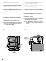
1
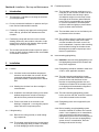
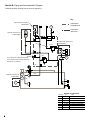
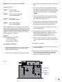
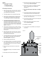
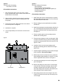
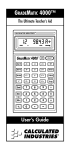
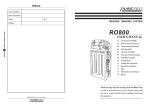
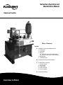
Instruction,Operation and
Maintenance Manual
Flowserve Circulator
Table of Contents
Section
A Installation, Start-up and Maintenance
1. Introduction
2. Installation
3. Start-up
3.4 Pressure control valve adjustment
3.5 Pressure relief valve reset procedure
4. Maintenance
5. Troubleshooting
B Piping and Instrumentation Diagram
C
Experience In Motion
Kit Installation Instruction
1. Pressure switch
2. Accumulator
3. Level switch
4. Heat exchanger
5. Pressure gauge
D Customer Drawings
Section A: Installation, Start-up and Maintenance
2.3 Foundation/placement
1
2.3.1 The foundation (customer steel base or con-
crete pad) for the circulator should be flat and level, with anchor bolts set firmly in place. A foundation weight of not less than 3 times the weight of the circulator (when filled with barrier fluid) is recommended as a minimum for concrete foundations. Steel baseplates shall have sufficient rigidity to prevent distort-
ing the circulator after bolt down.
2.3.2 The foundation must be free of all debris prior to placement of the circulator.
2.3.3 The circulator reservoir is fabricated such that the top is level. Gently lower the circulator onto the foundation and check to see if the level is maintained. If required, shim mounting feet level before bolting the circulator down. Mounting bolts should be torqued per manu-
facturer’s specifications.
Introduction
1.1 This manual is a valuable tool covering the circulator
you have purchased.
1.2 Do not proceed with installation or operation until you
have read and understand this manual.
1.3 Following is a step-by-step approach covering installation, start-up, operation and maintenance of the
circulator.
1.4 Familiarize yourself with and refer to the circulator
drawing (Section B). Item numbers referred to in this
manual can be found on this drawing. Order specific
drawings can be found in Appendix 1.
1.5 The circulator purchased includes only the kit options
shown on these drawings. Additional kits are available
as described in Section C.
2
2.1.1 Circulator location and ambient temperature extremes must be taken into account. All inter-
connecting piping/tubing must be thermally protected to insure a continuous flow of barrier fluid.
2.4.1 Definition: Interconnecting piping/tubing is all fluid piping/tubing between the circulator and the process equipment.
2.4.2 Piping/tubing should be installed to meet local codes or other applicable standards.
2.4.3 The interconnecting piping/tubing system should be sized and constructed to minimize pressure losses and should not be less than the corresponding pipe/tube size and schedule as contained in the circulator (refer to the piping and instrumentation diagram of pipe size, schedule and material).
2.1.2 Shading the circulator from direct sunlight is recommended.
2.1.3 Installation must take place during a time when ambient temperatures are above freezing or with all fluid lines protected from damage.
2.4.4 The interconnecting piping/tubing system, both to and from the seal, should be construct-
ed of similar material as the circulator.
2.1.4 Follow notes listed on the circulator order drawings, in Appendix 1, covering utility require-
ments and control component points.
2.4.5 Piping/tubing must not be supported by the circulator.
2.4.6 Before installing, the piping/tubing system should be checked for freedom from contami-
nation. If not completely free of contaminants, clean and flush the entire interconnecting piping/tubing system before connecting the cir-
culator. Once you are sure the piping/tubing system is free of contamination, drain the flushing media and air blow dry.
2.2 Lifting/uncrating
2
Installation
2.1 Location
2.4 Interconnecting piping/tubing
2.2.1 Remove the crating carefully to avoid damag-
ing components.
2.2.2 The circulator must be lifted only from the bottom or by the lifting lugs when provided. Lift carefully to avoid damaging circulator components.
Do not, under any circumstances, use the circulator to
flush the interconnecting piping/tubing. Using the circulator to flush the interconnecting piping/tubing will
void the warranty. The circulator is flushed clean and
sealed at the factory.
2.4.7 Connections to circulator: A teflon paste pipe sealant is recommended and should be applied no closer than two threads from the end of the fitting to avoid contamination.
3.3 This circulator is equipped with a Pressure Relief
Valve (PRV-1) and a Pressure Control Valve (PCV-1).
The pressure relief valve on the right end of the manifold is factory set at and should never be adjusted.
The pressure contol valve on the left end of the manifold is factory set and will need adjustment to meet the
requirements of the application. The pressure control
valve can be adjusted using the following procedure
and referring to the manufacturers service manual in
Appendix 2 of this manual.
2.4.7.1 Do not remove plugs from ports until you are ready to make a final connec-
tion.
2.4.7.2 Refer to the circulator drawings in Section B for connections to be made.
3
Start-up Operation
3.1 Initial start-up
3.1.1 Check all field connections in piping/tubing to see that the joints are tight. Also check and tighten circulator fasteners, which may have become loose during transit.
3.1.2 Verify the correct barrier fluid type with the seal manufacturer before filling. Fill the reservoir to the top of the level gauge through the filler port provided.
3.1.3 The pump/motor assembly does not require alignment.
3.1.4 Before connecting the motor power source. Disengage the pump/motor coupling. Connect the motor power source. Jog the motor (3-5 seconds) to check rotation against the rotation arrows. Reconnect the pump/motor coupling. Replace the coupling guard cover plate.
3.2 All instruments must be tied into the customer’s control panel to operate the main process equipment. Functions listed on the circulator drawings
are the minimum requirements necessary to insure
proper operation. The manufacturer may place more
stringentrequirements on sequencing of the main
process equipment. It is recommended the customer
contact the seal manufacturer to obtain a list of all
operational sequences and interlocks to insure safe
and efficient operation.
It is the customer’s responsibility to familiarize themselves with the instrumentation and controls mounted
on the circulator. The customer’s supplied control
panel shall at minimum provide the functions listed
and as described on the circulator drawings.
3.4 Pressure control valve adjustment
The pressure control valve located on the left end of the
manifold is factory set at 200 psig (1379 kPa) and will need
adjustment to meet the requirements of the application. Follow these steps to adjust the pressure control valve.
3.4.1 The fluid temperature in the circulator must be at the normal operating temperature to achieve the correct pressure setting.
3.4.2 To prevent accidental over pressurization of the seal, connect the seal supply port directly to the seal return port, bypassing the seal. This will protect the seal from high pressures during valve adjustment.
3.4.3 Completely open the pressure control valve on the left end of the manifold.
3.4.4 Start the circulator and allow to run long enough to remove any air from the system. All fluid flow should be through the pressure con-
trol valve, through the heat exchanger and back into the reservoir.
3.4.5 Slowly close the pressure control valve on the left end of the manifold until the desired system pressure is achieved.
3.4.6 Shut down the circulator and return any piping to its original, normal operating configuration. The pressure control valve is now set to the proper pressure.
3
3.5 Pressure relief valve reset procedure
4.2 Service of suction strainers
The pressure relief valve on the right end of the manifold is factory set at 450 psig (3103 kPa) and should
not require adjustment. If however, the relief valve setting
has become suspect or the seal requires a lower setting,
follow these steps to reset the pressure relief valve. Do not
exceed 450 psig (3103 kPa).
To service the suction strainer, the circulator pump must
be shut off. Make sure the circulator motor cannot be auto
started. Remove top plate of reservoir. Strainers should be
checked and cleaned every 12 months.
3.5.1
To prevent accidental over pressurization of the seal, connect the seal supply port directly to the seal return port. This will protect the seal from high pressures during valve adjust-
ment.
3.5.2 Completely close the pressure control valve on the left end of the manifold.
3.5.3 Completely open the pressure relief valve on the right end of the manifold.
3.5.4
Start the circulator and allow to run long enough to remove any air from the system. All fluid flow should be through the pressure relief valve and into the reservoir.
3.5.5 Carefully close the pressure relief valve on the right end of the manifold until the desired pres-
sure is maintained in the system.
3.5.6
Shut down the circulator. The pressure relief valve is now set at and will not need further adjustment. Higher adjustment of the pressure relief valve may cause damage to the pump.
3.5.7 Once the pressure relief valve is set, reset the pressure control valve setting. Refer to the previous section of this document.
4
Maintenance
Caution:
Do not attempt to work on this system unless you have on safety glasses with side shields and you have completely read and understand this service manual.
4.1 Electrical/power input
4
Shut down all electrical power to the circulator prior to
attempting maintenance.
4.3 Customer electrical
It is the customer’s responsibility to provide a control panel
to properly operate the circulator.
4.4 Pressure filter
4.4.1
Caution: Do not attempt to open any lines, loosen fittings or remove filter canister unless all pressure gauges read zero pressure. Be sure that instrument isolation valves are open to gauges. Always wear safety goggles with side shields when performing mainte-
nance or making adjustments to the system.
4.4.2 After 8 hours of initial start-up or sooner per clogging indicator, the filter element should be changed.
4.4.3 Change element every time the clogging indi-
cator on the filter is in the red service filter position.
4.5 Questions
Do not hesitate to contact your Flowserve representative
with any questions you have concerning the installation,
operation or maintenance of the circulator.
5
Troubleshooting
Problem
Probable Cause
Unable to maintain Pressure
(Low Pressure)
Low pressure control valve setting: Follow the procedure in this document to adjust the valve as required.
Low pressure relief vale setting: Fluid is bypassing the through the valve and returning to the tank. Follow the procedure in this document to adjust the valve as required.
Unable to maintain Pressure
(High Pressure)
High pressure control valve setting: Follow the procedure in this document to adjust the valve as required.
Low Temperature/High Viscosity: Low temperature can cause the barrier fluid to have a too high of viscosity, creating high pressure loss on the seal supply and return lines. Insulate line to maintain temperature.
Poor supply and return line piping: The supply and return line piping should be sized and constructed to eliminate as much pressure loss as practical.
Unable to maintain Flow
Low pressure relief vale setting: Follow the procedure in this document to adjust the valve as required.
Worn Pump: If the circulator pump wears the discharge flow rate will decrease. This will be more apparent at higher pressures. Measure the flow rate at normal operating pressure and again at 1/2 normal operating pressure. If the flow increases more than 20% then the pump may need to be replaced.
Note: pump wear can be accelerated by poor quality barrier fluid and/or failure to maintain system filtration, and prevent ingression.
5
Section B: Piping and Instrumentation Diagram
Customer specific drawings can be found in Appendix 1.
Key
Optional pressure switch kit
(UKDPU9802)
PS
1
1
2
Optional accumulator kit
(UKDPU9806)
Supply
PS-1
Pl
1
Return
contained in manifold block
contained in optional kit
PI-1
A
Optional heat exchanger kit
(UKDPU9806)
1-1/4"
CV-1
CV-2
PCV-1
H
5/8"
6
B
Test Port
RV-1 Factory set at 450 psig (3103 kPa)
PCV-1 Factory set at 200 psig (1379 kPa)
Reset PCV-1 as required
7
1/4"
C
RV-1
Pl
2
1/2"
1/2"
P
1"
Optional level switch kit
(UKDPU9805)
LG
1
Tl
1
5/8"
3/4"
1/2"
LS
1
1/2"
4
5
3/4" 3
Schedule of connections
connection size
1/2" NPT
1
1/2" NPT
2
6
3
4
5
6
3/4" NPT
1/2" NPT
1/2" NPT
3/8" NPT
7
3/8" NPT
service
seal supply
seal return
drain (plugged)
cooling water supply (plugged)
cooling water return (plugged)
cooling water supply (option)
cooling water return (option)
Section C: Kit Installation Instructions
3. Thread 1/2” side of adapter into pressure switch finger tight.
Available kit options
4. Option 1: Pressure switch
Part code UKDPU9802
Option 2: Safety feature (accumulator)
Part code UKDPU9803
Place an open end wrench on the ball valve and an open end wrench on the pressure switch connection nut. Tighten connection until ball valve handle is facing the pressure switch adjustment cover. Do not over
tighten.
5. Apply Teflon tape and/or Jomar pipe dope or equal to the ball valve threads. Start no closer to the end of the treads than the 2nd thread.
Option 3: Level switch
Part code UKDPU9805
6. Clean any dirt or debris from the 1/4” NPT connection on the bottom of the manifold block. Remove the 1/4” NPT plug from the bottom of the manifold block.
Option 4: External heat exchanger
Part code UKDPU9806
Before installing any kit to the circulator, it must be shut
down and disconnected from the main power source. Safety glasses with side shields must be worn when working
on the unit. Clean the unit of all debris. Familiarize yourself
with these instructions and the components for each kit
before beginning any installation.
Option 1
The pressure switch kit includes:
• 1/4” NPT ball valve
• 1/4” x 1/2” NPT adapter
• Pressure switch, 1/2” NPT
7. Thread the pressure switch assembly into the mani-
fold block finger tight.
8. Place an open end wrench on the ball valve and tighten into the manifold block. Tighten connections until ball valve handle is facing away from the circulator. Do not over tighten. See Figure 1.
9. Rotate the ball valve handle to the off position. Ball valve is off when handle is rotated 90° to the ball valve ports.
10. Installation is complete.
Kit installation instructions
1. Apply Teflon tape and/or Jomar pipe dope or equal to adapter threads. Start no closer to the end of the threads than the 2nd thread.
2. Thread 1/4” side of adapter into ball valve finger tight.
Figure 1
11. It is the responsibility of the customer to wire and set the pressure switch.
12. The pressure switch can be put into service once the unit is restarted and the customer has verified the circulator is running normal. Rotate the ball valve handle 90° to allow flow to the switch.
Xxxx xxxxxx xxxx
xxxxxxxx xx xxxx
xxxxxx xxxxxxxxx
xxxxxx xxxxxxxxx
Seal Support System
Part No.
Xxxx Xx.
Xxxxxx
Part No.
Xxxxx xx xxxxxxxxxxx
to
Xxxxx xx xxxxxxxxx
to
PSI
Xxxxxxx Xxxxx Xxxx Xx
Xxxxxxx
ball valve
adapter
pressure
switch
7
Option 2
The safety feature kit includes:
• Accumulator, 1-1/4” NPT
• 1-1/4” NPT pipe nipple
• 1/4” tubing and tube fittings
Kit Installation Instructions:
1. Apply Teflon tape and/or Jomar pipe dope or equal to 1-1/4” pipe nipple threads. Start no closer to the end of the threads than the 2nd thread.
2. Thread pipe nipple into the accumulator finger tight.
3. Clean any dirt or debris from the 1-1/4” NPT connec-
tion on the top of the manifold block. Remove the 1-1/4” NPT plug from the top of the manifold block.
4. Thread the nipple/accumulator assembly into the manifold block. Tighten assembly until the 1/4” NPT connection in the accumulator is facing the front of the manifold block. With wrench placed on the connection end of the accumulator tighten assembly. Do not over tighten. See figure 2.
5. Clean any dirt or debris from the 1/4” NPT connection on the top of the manifold block. Remove the 1/4” NPT plugs from the and accumulator and the top of the manifold block.
6. Apply Teflon tape and/or Jomar pipe dope or equal to tube fitting NPT threads. Start no closer to the end of the threads than the 2nd thread.
13. Hold tubing into position and tighten each nut with a wrench until tight. Do not over tighten.
14. Clean any dirt or debris from cartridge connections. Remove cartridge plugs from manifold block. See Figure 2.
15. Do not use Telfon tape or pipe dope on cartridge valves.
16. Insert and finger tighten the needle valve cartridge into the cavity on the front of the manifold block.
17. Insert and finger tighten the check valve cartridge into the bottom of the manifold block.
18. Insert and finger tighten the check valve cartridge into the top of the manifold block.
19. Tighten valves with open-end wrench or socket wrench. Do not over tighten.
20. Installation is complete.
21. It is the customer’s responsibility to pre-charge the accumulator.
Figure 2
7. Thread tube fittings into the accumulator and manifold block. Tighten into accumulator and manifold block. Do not over tighten. See Figure 2.
accumulator
tubing and
fittings
8. Remove tube fitting nut and ferrule.
9. Insert tubing into fittings on accumulator and manifold block. Verify tubing ends are the correct length. Cut to fit if required. Proceed to the next step once tubing is the correct length.
Xxxxxx
to
Xxxxx xx xxxxxxxxx
to
Xxxxxxx
11. Insert tubing into fittings on accumulator and block manifold.
12. Slide fitting nuts into place and finger tighten.
8
Part No.
Xxxxx xx xxxxxxxxxxx
Xxxxxxx Xxxxx Xxxx Xx
10. Slide tube fitting nut and ferrule onto each end of tubing.
nipple
Xxxx xxxxxx xxxx
xxxxxxxx xx xxxx
xxxxxx xxxxxxxxx
xxxxxx xxxxxxxxx
Seal Support System
Part No.
Xxxx Xx.
PSI
needle
valve
check valve
pilot to
open
check
valve
Option 3
The level switch kit includes:
• Level switch, 3/4” NPT
Kit Installation Instructions
1. Apply Teflon tape and/or Jomar pipe dope or equal to level switch threads. Start no closer to the end of the threads than the 2nd thread.
2. Clean any dirt or debris from the reservoir connection. Remove 3/4” plug from reservoir coupling next to the level gauge.
3. Thread in level switch. Tighten with flats on the shaft in the vertical position. See figure 3.
4. Installation is complete.
5. It is the responsibility of the customer to wire the level switch.
Option 4
The heat exchanger kit includes:
• Heat exchanger
• Heat exchanger mounting brackets
• U-bolts with nuts and mounting pad (quantity 2)
• Tube fittings (quantity 3)
• Tubing (quantity 3)
Kit Installation Instructions
1. Apply Teflon tape and/or Jomar pipe dope or equal to the 4 tube fittings threads. Start no closer to the end of the threads than the 2nd thread.
2. Remove tubing from the manifold block to the filter and discard.
3. Attach heat exchanger mounting brackets with two (2) 1/2” 13 mounting bolts through the holes provided in the top of the manifold block and finger tighten bolts. See Figure 4.
4. Place a mounting pad on each mounting bracket between the mounting holes.
Figure 3
5. 6. Install the U-bolts over the heat exchanger and through the mounting pads and brackets and finger tighten nuts.
Xxxx xxxxxx xxxx
xxxxxxxx xx xxxx
xxxxxx xxxxxxxxx
xxxxxx xxxxxxxxx
Seal Support System
Part No.
Xxxx Xx.
Xxxxxx
Part No.
Xxxxx xx xxxxxxxxxxx
to
Xxxxx xx xxxxxxxxx
to
Place the heat exchanger on the mounting pads. Shell connection should be facing up with the cooling media connections facing the drain side of the reservoir. See Figures 4 and 5.
PSI
Xxxxxxx Xxxxx Xxxx Xx
Xxxxxxx
7. Install and tighten tube fittings into the heat exchanger shell connections. Do not over tighten.
8. While facing the unit from the block side, position the heat exchanger approximately 4-1/2 inches (114 mm) from the right side of the reservoir. See Figure 4.
xxxxx
9. Level the heat exchanger across the cooling media ports. See figure 5.
level switch
shaft position
10. Remove the fitting nuts and ferrules from the fittings on the left side of the heat exchanger and the mani-
fold block. Assemble the short piece of tubing, 90° union tube fitting and the short 90° bent tube into the heat exchanger and the manifold block.
11. Verify tubing ends are the correct length. Cut to fit if required. Proceed to the next step once tubing is the correct length.
9
12. Slide fitting nuts into place and finger tighten.
19. Hold tubing into position and tighten each nut with a wrench until tight. Do not over tighten.
13. Remove the fitting nuts and ferrules from the fittings on the right side of the heat exchanger and the filter. Slide them onto the “L” shaped tubing.
14. Insert the “L” shaped tube into the right side of the heat exchanger and the filter. Verify tubing ends are the correct length. Cut to fit if required. Proceed to the next step once the tubing is the correct length.
15. Slide tube fitting nut and ferrule onto each end of the tubing.
16. Insert tubing into the fittings on the heat exchanger and filter.
17. Slide fitting nuts into place and finger tighten.
18. Square the mounting brackets with the manifold block. See Figure 4. Tighten the mounting bolts and the U-
bolt nuts. Do not over tighten.
20. Disconnect the existing cooling media lines from the reservoir’s internal heat exchanger.
21. Apply Teflon tape and/or Jomar pipe dope or equal to the 1/2” NPT plug threads. Start no closer to the end of the threads than the 2nd thread.
22. Thread the plugs into the reservoir’s internal heat exchanger and tighten. Do not over tighten.
23. Installation is complete.
24. It is the responsibility of the customer to connect to the heat exchanger cooling media ports.
Note: For additional cooling capacity run cooling media through both the internal and external cooling coils in series.
Figure 5
Figure 4
cooling port
orientation
mounting
bracket
mounting
bracket
4.50"
heat exchanger
tubing and
fittings
10
Section D: Customer Drawings
Note: The following documents are typically provided as
part of the order documentation package along with
this IOM.
Appendix 1:
Order Drawings
- Piping and Instrumentation Diagram
- General Arragement
- Bill of Material
- Electrical
Appendix 2: Component Information
- Catalog
- Component IOMs
11
TO REORDER REFER TO
B/M #
F.O.
FIS187eng ORG 4/10 Printed in USA
To find your local Flowserve representative
and find out more about Flowserve Corporation,
visit www.flowserve.com
Flowserve Corporation has established industry leadership in the design and manufacture of its products. When
properly selected, this Flowserve product is designed to perform its intended function safely during its useful life.
However, the purchaser or user of Flowserve products should be aware that Flowserve products might be used
in numerous applications under a wide variety of industrial service conditions. Although Flowserve can provide
general guidelines, it cannot provide specific data and warnings for all possible applications. The purchaser/user
must therefore assume the ultimate responsibility for the proper sizing and selection, installation, operation, and
maintenance of Flowserve products. The purchaser/user should read and understand the Installation Instructions
included with the product, and train its employees and contractors in the safe use of Flowserve products in connection
with the specific application.
While the information and specifications contained in this literature are believed to be accurate, they are supplied for
informative purposes only and should not be considered certified or as a guarantee of satisfactory results by reliance
thereon. Nothing contained herein is to be construed as a warranty or guarantee, express or implied, regarding any
matter with respect to this product. Because Flowserve is continually improving and upgrading its product design,
the specifications, dimensions and information contained herein are subject to change without notice. Should any
question arise concerning these provisions, the purchaser/user should contact Flowserve Corporation at any one of
its worldwide operations or offices.
© Copyright 2010 Flowserve Corporation
flowserve.com
USA and Canada
Tulsa, Oklahoma, USA
Telephone: 1 918 599 6062
Telefax: 1 918 583 1071
Europe, Middle East, Africa
Roosendaal, the Netherlands
Telephone: 31 165 581400
Telefax: 31 165 554590
Asia Pacific
Singapore
Telephone: 65 6544 6800
Telefax: 65 6214 0541
Latin America
Mexico City
Telephone: 52 55 5567 7170
Telefax: 52 55 5567 4224