1
A-MCB2 Product
User's Manual
Firmware 5.00 and up
Last Update: December 10 2015
Visit www.zaber.com/wiki for more recent updates.
Zaber Technologies Inc.
#2 - 605 West Kent Ave. N.
Vancouver, British Columbia
Canada, V6P 6T7
Table of Contents
Disclaimer...........................................................................................................................................................1
Conventions used throughout this document..................................................................................................2
Precautions.........................................................................................................................................................3
Device Overview.................................................................................................................................................4
Connectors..............................................................................................................................................4
Power................................................................................................................................................4
Digital Inputs / Outputs....................................................................................................................4
Analog Inputs...................................................................................................................................5
RS232 Communications...................................................................................................................6
RS485 Communications...................................................................................................................6
USB Communications......................................................................................................................7
Motor Interface.................................................................................................................................7
Indicators.................................................................................................................................................8
Communications.....................................................................................................................................8
Installation........................................................................................................................................................10
Daisy-Chaining Devices.......................................................................................................................10
Grounding.............................................................................................................................................11
Quick Tutorial..................................................................................................................................................13
Initial Setup...........................................................................................................................................13
Initialization..........................................................................................................................................14
Using the Device...................................................................................................................................14
Modifying Device Settings.............................................................................................................14
Built-In Help...................................................................................................................................14
Manual Control................................................................................................................................................16
Velocity Mode......................................................................................................................................16
Displacement Mode..............................................................................................................................16
Summary of knob functionality............................................................................................................16
Trajectory Control and Behaviour.................................................................................................................17
Software Position Limits......................................................................................................................17
Movement Speed..................................................................................................................................17
Quick Command Reference............................................................................................................................18
ASCII Protocol.....................................................................................................................................18
Quick Commands...........................................................................................................................18
Quick Device Settings....................................................................................................................19
Binary Protocol.....................................................................................................................................23
Troubleshooting A-Series Closed-Loop Motion Devices..............................................................................26
Front Panel Indicators...........................................................................................................................26
Manual Control.....................................................................................................................................27
Unexpected Behaviour..........................................................................................................................27
i
Table of Contents
Troubleshooting A-Series Closed-Loop Motion Devices
Communication Errors..........................................................................................................................27
Slipping and Stalling.............................................................................................................................29
Warranty and Repair......................................................................................................................................30
Standard products..................................................................................................................................30
Custom products...................................................................................................................................30
How to return products.........................................................................................................................30
Email Updates..................................................................................................................................................31
Contact Information........................................................................................................................................32
Appendix A - Available Communications Ports...........................................................................................33
Finding Installed Serial Ports................................................................................................................33
Windows.........................................................................................................................................33
Linux..............................................................................................................................................33
Appendix B - USB Driver Installation...........................................................................................................35
Compatible Devices..............................................................................................................................35
Windows...............................................................................................................................................35
Download.......................................................................................................................................35
Windows Vista, 7 & 8....................................................................................................................35
Windows XP...................................................................................................................................39
Linux.....................................................................................................................................................41
OS X.....................................................................................................................................................41
Appendix C - I/O Usage and Examples..........................................................................................................42
Digital Inputs........................................................................................................................................42
Digital Outputs......................................................................................................................................43
Analog Inputs........................................................................................................................................43
ii
Disclaimer
Zaber’s devices are not intended for use in any critical medical, aviation, or military applications or situations
where a product's use or failure could cause personal injury, death, or damage to property. Zaber disclaims
any and all liability for injury or other damages resulting from the use of our products.
Disclaimer
1
Conventions used throughout this document
• Fixed width type indicates communication to and from a device. The ↵ symbol indicates a
carriage return, which can be achieved by pressing enter when using a terminal program.
• An ASCII command followed by (T:xx) indicates a legacy T-Series Binary Protocol command that
achieves the same result. Not all ASCII commands have an equivalent legacy counterpart. e.g.:
move abs 10000 (T:20:10000) shows that a move abs ASCII command can also be
achieved with binary command number 20.
• All devices support the Binary Protocol, however the ASCII Protocol is only supported in devices
with firmware version (T:51) 6.06 and above.
Conventions used throughout this document
2
Precautions
The A-MCB2 series of stepper motor controllers are intended to drive a wide variety of motors. It is not
possible to choose factory default settings that will work with every motor that may be connected. Therefore,
you will need to change some of the settings from the default values to match the motor you are driving. For a
Zaber peripheral device, a complete setup can be accomplished by configuring the peripheralid (T:66) setting
with the peripheral's ID number. See the detailed usage examples for more information on how to modify the
settings, particularly for non-Zaber peripherals. Damage to the actuator may result if the recommended
settings are set improperly.
WARNING: Serious damage can occur to stepper motor products when operated with significantly
higher-than-rated current. The A-MCB2 controller can provide up to 2.5A of current to a peripheral.
BEFORE CONNECTING A NEW DEVICE to the A-MCB2 controller, it is important to set the correct
motor parameters in the controller. Please check the rated current for any peripheral device before
changing the current settings on the A-MCB2 from the default values. To put the A-MCB2 controller into
safe-mode (low current) settings, configure the peripheralid (T:66) setting to 0. If you have any questions,
please contact Zaber Technical Support
Precautions
3
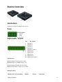
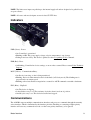
Device Overview
Connectors
All images are shown looking into the device.
Power
Pin Description
1 Chassis
2 GND
3
24 - 48 V
Digital Inputs / Outputs
Pin
1
2
3
4
5
6
7
8
9
10
Description
Digital In 1
Digital In 2
Digital In 3
Digital In 4
Digital In Common
Digital Out 1
Digital Out 2
Digital Out 3
Digital Out 4
Digital Out Common
Specifications
Maximum Input Voltage (per pin): 8.0V
Minimum Input Logic High Voltage: 1.5V
Maximum Output Current (per pin): 25mA
Maximum Switchable Voltage (per pin): 60V
Mating Products
Manufacturer & Part Number
Device Overview
Digikey
Mouser
element14
4
TE Connectivity 1-1986692-0
A104378-ND 571-1-1986692-0 83T4046
TE Connectivity 1-284506-0
A98378-ND
TE Connectivity 1-1986692-5
A104383-ND 571-1-1986692-5 83T4051
TE Connectivity 1-284506-5
571-2845065
571-12845060
08H0070
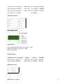
Equivalent Circuits
Analog Inputs
Pin
1
2
3
4
5
6
Description
+5V
GND
Analog In 1
Analog In 2
Analog In 3
Analog In 4
Specifications
Absolute Maximum Input Range (per pin): 0V - 12.8V
Nominal Input Range (per pin): 0V - 10.0V
Resolution: 0.0125V
Mating Products
Manufacturer & Part Number
Digikey
Mouser
element14
TE Connectivity 1986692-6
A104374-ND 571-1986692-6 83T4130
TE Connectivity 284506-6
A98377-ND
571-2845066
15H7338
Equivalent Circuit
Digital Inputs / Outputs
5
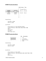
RS232 Communications
Pin
1
2
3
4
5
6
7
8
9
Previous
Transmit
Receive
Ground
-
Next
Receive
Transmit
Ground
-
Default Settings
• Baud Rate: 115200
• Protocol: ASCII
Specifications
• Supported Protocols: Zaber ASCII, Zaber Binary
• Supported Baudrates: 9600, 19200, 38400, 57600, 115200
• Bits: 8
• Parity: None
• Stop Bits: 1
• Flow Control: None
RS485 Communications
Pin
1
2
3
4
Description
+5V
A (Inverting)
B (Non Inverting)
GND
Default Settings
• Baud Rate: 115200
• Protocol: ASCII
Specifications
• Supported Protocols: Zaber ASCII
• Supported Baudrates: 1200, 4800, 9600, 19200, 38400, 57600, 115200
• Bits: 8
• Parity: None
RS232 Communications
6
• Stop Bits: 1
• Flow Control: None
Mating Products
Manufacturer & Part Number
Digikey
Mouser
Newark
TE Connectivity 284506-4
A98375-ND 571-2845064 12H8898
NOTE: When using the RS485 interface, the device will execute any global or broadcast commands but not
respond to them.
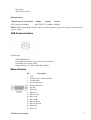
USB Communications
Specifications
• USB 2.0 Full Speed
• Communications Device Class, Abstract Control Model
• Default Protocol: Zaber ASCII
• Supported Protocols: Zaber ASCII, Zaber Binary
Motor Interface
Pin
1
2
3
4
5
6
7
8
9
10
11
12
13
14
15
RS485 Communications
Description
+5V
D Limit Sensor or Encoder Error
C Limit Sensor
Away Limit Sensor
Home Limit Sensor
Ground
Motor B1
Motor A1
Encoder +5V
Encoder A
Encoder B
Encoder Index
Encoder Ground
Motor B2
Motor A2
7
NOTE: The limit sensor inputs are pulled up to the internal supply rail and are designed to be pulled low by
an open collector.
NOTE: All sensor and encoder inputs are non-isolated 5V TTL lines.
Indicators
PWR (Green) - Power.
• On: Controller is operational.
• Blinking at 2Hz: The power supply voltage or device temperature is out of range.
• Fading in and out slowly: The device is parked. See the tools parking (T:65) command.
ERR (Red) - Error.
• On/blinking: Controller has lost its settings, or an error has occurred. Please contact Zaber Technical
Support.
MOT (Yellow) - Communication/Busy.
• On: Device is moving, or data is being transferred.
• Blinking: Device is under manual control via the knob (in Velocity mode). The blinking rate is
proportional to movement speed.
• Blinking at fixed rate: Packet corruption has occurred for ASCII commands sent with a checksum.
ENC (Blue) - Slip/Stall.
• On: The device is slipping.
• 2 short flashes every 1 sec: The stationary device has been forced out of position.
• On-Off cycle every 2 sec: The device has stalled and stopped.
Communications
The A-MCB2 supports multiple communications interfaces and processes commands through the currently
active interface, which is determined by the interface priorities. Enabling or connecting a higher priority
interface will cause any commands received over the lower priority interface(s) to be ignored.
Motor Interface
8
Interface Priority
1. USB
2. RS485
3. RS232
Daisy Chaining
Daisy Chaining is supported from USB to RS232 Next and RS232 Prev to RS232 Next. In order to chain from
USB to RS232 the comm.usb.protocol setting must be the same as the comm.rs232.protocol setting.
Communications
9
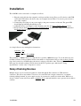
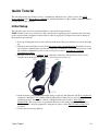
Installation
The A-MCB2 can be connected to a computer as follows:
1. Plug the serial cable into the computer's serial port and the device's Prev port. For devices with USB,
connect the USB cable to the device and your computer instead. There is no need to power-down or
reboot the computer.
2. Connect the power plug of your power supply to the power connector of the unit. The green LED
should light up indicating the unit has power.
3. Additional devices can simply be daisy-chained to the first. See Daisy-Chaining Devices below.
4. Install software from http://www.zaber.com/wiki/Software. For the initial setup, it is recommended
that Zaber Console is used.
As a simple first test, try entering these instructions:
/renumber↵ (T:2)
/1 home↵ (T:1)
/1 move rel 10000↵ (T:21:10000)
The parameter of 10000 in the move command above specifies 10000 microsteps. To see the microstep size
(default resolution) for the peripheral and how it translates to displacement, first go to the product overview
page, find your device, click through to the device's webpage, and click on the "Series Specs" tab. The
microstep size (default resolution) will be shown in the list of product specs either in the "Group
Specifications" section or the "Comparison" section.
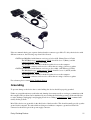
Daisy-Chaining Devices
Multiple devices can be connected together in a chain through the Prev and Next or USB and Next
connectors. This allows any number of devices to be controlled from a single connection to a computer,
reducing cabling demands. A power supply needs to be connected to each device in the chain. Whenever a
device is added or removed from a chain, a renumber (T:2) command should be sent to prevent device-address
conflicts.
Installation
10
Zaber recommends having two separate chains when the connector types differ. To daisy-chain devices with
different connectors, the following steps should be followed:
• DSUB9 and MiniDin 6 with firmware version at or below 6.05: (Binary Protocol Chain)
The DSUB9 devices' comm.protocol (T:123) should be set to 1 (Binary) and the
comm.rs232.baud (T:122) set to 9600.
The DSUB9 devices should be chained together closest to the computer
A T-DSUB9 connector can be used to connect the two strings of devices together.
• DSUB9 and MiniDin 6 with firmware version at or above 6.06: (ASCII Protocol Chain)
The Minidin6 devices' comm.protocol (T:123) should be set to 2 (ASCII) and the
comm.rs232.baud (T:122) set to 115200.
The DSUB9 devices should be chained together closest to the computer
A T-DSUB9 connector can be used to connect the two strings of devices together.
For assistance please contact Zaber Technical Support
Grounding
To prevent damage to the device due to static buildup, the device should be properly grounded.
Failure to ground the unit may result in the unit shutting down unexpectedly or ceasing to communicate with
the computer. This problem can be minimized by not touching the unit during operation. If the unit fails due
to static discharge, unplugging it and plugging it back in or sending a system restore (T:36) command will
usually fix the problem.
Most Zaber devices are grounded via the shield wire of the data cables. This should normally provide a path to
ground via the computer. For units which are being used without a computer, a ground lead should be
connected to the chassis pin of the power supply connector.
Daisy-Chaining Devices
11
Note: Encoder-embedded devices are sensitive to electrically noisy environments. Static discharges can affect
position calibration and cause unstable behaviour. If the device is behaving strangely, verify that the device is
properly grounded, reset the device (either by the system reset (T:0) command or by disconnecting then
reconnecting power), then re-initialize the device with the home (T:1) command.
Grounding
12
Quick Tutorial
The following tutorial uses Zaber Console to communicate with the device(s). Please refer to the ASCII
Protocol Manual and/or Binary Protocol Manual for detailed information on the available commands and how
to setup and use other software.
Initial Setup
The following steps need to be performed whenever a new unit is being installed.
NOTE: Ensure no motors are connected to the controller before applying power for the first time. Powering
up the controller with a peripheral connected before it has been properly configured can result in damage to
the peripheral and controller.
1. Power up all integrated devices and controllers in the chain. The power indicator on each should light
up.
2. Download and install Zaber Console from http://www.zaber.com/wiki/Software. Start Zaber Console
and select the communications port the first controller is connected to. For instructions on how to find
the available communication ports on your system, please refer to: Appendix A - Available
Communications Ports
3. From the Console, issue a renumber (T:2) command to all devices. The first device closest to the
computer in the chain will become device 1; the next, device 2 and so on.
4. On the new unit, configure the peripheralid setting of each axis with either the ASCII set peripheralid
command or the Binary T:66 command. The Peripheral Id for Zaber devices can be found on its
identification label. Alternatively a full list of Peripheral Ids can be found at: Zaber Support Peripheral IDs. This step needs to be performed whenever a motorized peripheral is changed for a
different type. If a 3rd party peripheral is being driven, please contact Zaber Technical Support for
assistance.
5. Connect the motorized peripherals.
Quick Tutorial
13
Initialization
Every time the controller is powered up or reset, the motorized peripheral(s) need to be returned to the home
position before they can be used. This is achieved by sending the home (T:1) command to the individual unit
or all units. Attempting to move the peripheral before it has been homed will result in an error, as shown
below:
/01 move rel 10000↵
@01 0 RJ IDLE WR BADDATA
If the device is being used under manual control, the motorized peripherals need to be driven to the minimum
(home) position before they will operate over their full range.
Using the Device
Several commonly used ASCII commands, and their Binary equivalents, are shown below. For a full list of
the available commands, please refer to the Command Reference section below.
Command
Description
/1 1 get pos↵ (T:60)
Query the current position of device #1 axis #1.
/1 1 move abs 10000↵ (T:20:10000) Move device #1 axis #1 to position 10000 microsteps.
/2 1 move
Move device #2 axis #1 in the negative direction by 12800 microsteps.
rel -12800↵ (T:21:-12800)
Decelerate and stop ALL axes on device 1.
/1 stop↵ (T:23)
An axis number of 0 or no no axis number implies all axes on the
devices, or the device itself.
Move ALL devices and ALL axes in the positive direction at the speed
153600.
/move vel 153600↵ (T:22:153600)
A device address of 0 or no device address implies all devices in the
chain.
Modifying Device Settings
Here are some examples if you would like to customize particular device settings. Refer to the ASCII Settings
or Command Reference section for detailed descriptions of each setting.
Command
/1 set maxspeed 100000↵ (T:42:100000)
/1 get maxspeed↵ (T:53:42)
/1 system restore↵ (T:36)
Description
Set the speed of the all axes on the device.
Query the axes' speed.
Restore all the settings of device 1 to the default.
Built-In Help
Zaber A-Series devices (with ASCII support) feature a built-in help guide, providing a quick and easy
reference for all Commands and Settings that the device has. To access the help, send: /1 help↵
The device will respond with a detailed description on how to access specific information about commands
and replies, as shown below:
@01 0 OK IDLE WR 0
Initialization
14
#01
#01
#01
#01
#01
#01
#01
#01
0
0
0
0
0
0
0
0
COMMAND USAGE:
'/stop'
stop all devices
'/1 stop'
stop device number 1
'/1 2 stop'
stop device number 1 axis number 2
Type '/help commands' for a list of all top-level commands.
Type '/help reply' for a quick reference on reply messages.
Visit www.zaber.com/support for complete instruction manuals.
To access help for a specific command, for example the move command, send:
/1 help move↵
@01 0 OK IDLE -- 0
#01 0 move abs {x}
#01 0 move rel {x}
#01 0 move vel {x}
#01 0 move min
#01 0 move max
Built-In Help
Move
Move
Move
Move
Move
to
by
at
to
to
absolute position
relative position
constant velocity
minimum position
maximum position
15
Manual Control
The A-Series range of motion control products are integrated with a depressible knob with 20 detents per
revolution, allowing devices to be controlled without the use of a computer. There are two manual movement
modes available, Velocity and Displacement: switch between these modes by holding down the knob for 1
second or via configuring the knob.mode (T:109) setting.
Upon power-up, the device will only travel towards the motor from its start-up position until the home
position is reached. Once the device has been manually homed, the full range of travel becomes available.
Velocity Mode
Turn the knob clockwise to move the device in the positive direction (extend) or counter-clockwise for
negative direction (retract). Each detent of the knob increases the speed of the carriage.
There are 16 speeds in each direction. The velocity profile and maximum speed can be configured via the
knob.speedprofile (T:112) and knob.maxspeed (T:111) settings. The device stops and resets the knob upon
arriving at the end of travel.
Displacement Mode
Turn the knob clockwise to move the device in the positive direction (extend), counter-clockwise for negative
direction (retract). Each detent of the knob moves the device a fixed number of microsteps, specified by the
knob.distance (T:110) setting. The device moves at the speed specified by the maxspeed (T:42) setting, or the
slower of speed and limit.approach.maxspeed (T:41) if the device has not been homed. If there are fewer than
knob.distance (T:110) microsteps to the end of travel and another move is requested, the device will move to
the end of travel and then stop.
Summary of knob functionality
• Turning the knob:
Moves the device in the direction of knob turn.
• Pressing the knob:
Decelerates and stops the device (identical to a Stop command).
Instantly stops the device, if the device is already decelerating.
• Pressing and holding the knob for 1 sec:
Toggles between Velocity Mode and Displacement Mode.
Manual Control
16
Trajectory Control and Behaviour
This section describes the behaviour of the device trajectory when a movement command is issued.
Software Position Limits
The travel range of the device is confined by the Minimum Position and Maximum Position settings. The
factory settings for the devices are configured to match the physical travel range. If a customized range is
desired, it can be changed via configuring the limit.min (T:106) and limit.max (T:44) settings to appropriate
values.
Minimum Position
When Current Position is less than the Minimum Position value, the device cannot move in the
negative direction (towards the motor).
Maximum Position
When Current Position is greater than the Maximum Position value, the device cannot move in the
positive direction (away from the motor).
Movement Speed
The movement speed of the device depends on device status and various speed settings. If the device has not
been initialized by the home (T:1) command or by moving towards the home end of the device, movement
speed will be constrained to fail-safe values. The home status of the device can be determined by reading the
limit.sensor.triggered (T:53) setting for the home sensor. The binary command additionally requires a value of
103.
Movement speed of the device is specified below:
move vel (T:22)
The device will move at the specified speed regardless of home status.
Knob manual movement in Velocity Mode
The device will move at the specified speed regardless of home status.
The speed is specified by the knob.speedprofile (T:112) and knob.maxspeed (T:111) settings.
Other movement commands - When device has not been homed
The device will move at the slower of the maxspeed (T:42) and limit.approach.maxspeed (T:41)
settings.
Other movement commands - When device has been homed
The device will move at the speed specified by the maxspeed (T:42) setting.
Trajectory Control and Behaviour
17
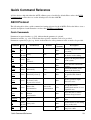
Quick Command Reference
A-Series devices ship with either the ASCII or Binary protocol enabled by default. Please refer to the RS232
Communications section above to see the default protocol for the A-MCB2.
ASCII Protocol
The following table offers a quick command and setting reference for the A-MCB2. Follow the links to view a
detailed description of each instruction or refer to the ASCII Protocol Manual.
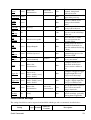
Quick Commands
Parameters in square brackets, e.g. [clr], indicate that the parameter is optional.
Parameters in italics, e.g. value, indicate that data, typically a number, needs to be provided.
Parameters separated by a pipe, e.g. abs|rel, indicate that one of the parameters in the set need to be provided.
Command
estop
get
help
Scope
Parameter(s)
Axis
Device
setting
and Axis
commands
Device reply
command ...
Returns
Firmware
Versions
0
6.06+
value
6.06+
0
6.06+
0
6.06+
Description
Instantly stops motorized
movement.
Retrieves the current value of
the device or axis setting.
Displays the help information
for the system.
Moves the axis to the home
position.
Returns the number of I/O
channels the device has.
Returns the current value of
the specified I/O channel
type.
home
Axis
io info
Device
[ai|ao|do|di]
ports
6.06+
io get
Device
ai|ao|do|di [channel]
value
6.06+
io set
Device
ao channel value
do channel value
0
do port value value2...
6.06+
Sets the specified output
channel to value.
lockstep
Device
Refer to the
documentation
Refer to the
documentation
6.15+
Sets up and controls
synchronized motion of a set
of parallel axes.
move
Axis
abs|rel|vel value
min|max
stored number
0
6.06+
Moves the axis to various
positions along its travel.
renumber
Device
value
0
6.06+
set
Device
setting value
and Axis
0
6.06+
stop
Axis
0
6.06+
Quick Command Reference
Renumbers all devices in the
chain.
Sets the device or axis setting
setting to the value.
Decelerates the axis and
brings it to a halt.
18
Refer to the
documentation
6.12+
system reset Device
0
6.06+
system
restore
Device
0
6.06+
tools echo
Device
0
6.06+
tools
findrange
Axis
0
6.10+
tools
gotolimit
Axis
limit dir action update 0
6.06+
tools
parking
Device
state|park|unpark
0|1
6.06+
tools
setcomm
Device
rs232baud protocol
0
6.06+
tools
storepos
Axis
number
[position|current]
0|position
6.06+
trigger
Device
Refer to the
documentation
0
6.06+
stream
Device
trigger dist Device
trigger time Device
Refer to the
documentation
(message)
number axis
displacement
0
number enable [count]
number disable
number period
number enable [count] 0
number disable
6.06+
6.06+
virtual
Device
Refer to the
documentation
Refer to the
documentation
6.18+
warnings
Axis
[clear]
0
6.06+
Performs an action related to
streamed, interpolated
multi-axis motion.
Resets the device, as it would
appear after power up.
Restores common device
settings to their default
values.
Echoes the provided message
(if any) back to the user.
Uses the home and away
sensors to set the valid range
of the axis.
Moves the axis to a limit
sensor and performs the
provided actions.
Parking allows the device to
be turned off and used at a
later time without first having
to home.
Sets RS232 baud rate and
communication protocol for
RS232 and USB.
Stores a number of positions
for easy movement.
Configures actions to be
performed on the device
when a certain condition is
met.
Configures a trigger to toggle
a digital output line every
displacement microsteps.
Configures a periodic trigger
to toggle a digital output line
every period milliseconds.
Sets up and controls a pair of
axes to allow movement
along a virtual axis.
Displays the active device
and axis warnings, optionally
clearing them if applicable.
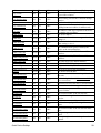
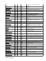
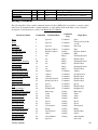
Quick Device Settings
The settings listed below can be inspected and modified with the get and set commands described above.
Setting
Quick Commands
Scope Writable
Firmware
Versions
Description
19
accel
Axis
Yes
6.06+
cloop.counts
Axis
Yes
6.06+
cloop.duration.max
Axis
Yes
6.17+
cloop.mode
Axis
Yes
6.06+
cloop.stalltimeout
Axis
Yes
6.06+
cloop.steps
Axis
Yes
6.06+
comm.address
Device Yes
6.06+
comm.alert
Device Yes
6.06+
comm.checksum
Device Yes
6.06+
comm.protocol
Device Yes
6.06+
comm.rs232.baud
Device Yes
6.06+
comm.rs232.protocol
Device Yes
6.09+
comm.rs485.baud
comm.rs485.enable
comm.rs485.protocol
comm.usb.protocol
deviceid
Device
Device
Device
Device
Device
Yes
Yes
Yes
Yes
No
6.09+
6.09+
6.09+
6.09+
6.06+
driver.current.hold
Axis
Yes
6.06+
driver.current.max
Axis
No
6.16+
driver.current.run
driver.dir
Axis
Axis
Yes
Yes
6.06+
6.06+
driver.temperature
Axis
No
6.06+
encoder.count
Axis
Yes
6.06+
encoder.dir
Axis
Yes
6.06+
encoder.error
Axis
No
6.17+
encoder.filter
Axis
Yes
6.06+
encoder.index.count
Axis
Yes
6.06+
encoder.index.mode
Axis
Yes
6.06+
encoder.index.phase
Axis
Yes
6.06+
Quick Device Settings
Sets the acceleration used to modify the speed.
The number of counts generated by the encoder
for one full revolution.
Direct reading encoder fine correction attempt
duration.
Sets the closed loop control mode.
The amount of time to wait after a
stall/displacement condition, in milliseconds.
The number of full steps required for the motor
to complete one revolution.
The device address.
The device will send alert messages when this
setting is 1.
The device includes checksums in its messages
if this setting is set to 1.
The communications protocol used by the
device on the current interface.
The baud rate used by RS232 Prev and Next
interfaces.
The protocol used by RS232 Prev and Next
interfaces.
The baud rate used by RS485 interface.
Enables the RS485 interface.
The protocol used by RS485 interface.
The protocol used by the usb interface.
The device id for the unit.
Current used to hold the motor in position, in 25
mA units.
Maximum legal value of driver.current.hold and
driver.current.run.
Current used to drive the motor, in 25 mA units.
Reverse the motor driver output direction.
The current temperature of the axis driver, in
degrees Celsius.
The recorded counts of the axis encoder.
Inverts the counting direction for the axis
encoder.
Position error measured by encoder.
Enable and set up digital filtering of the encoder
inputs.
The recorded counts of the axis encoder index
pulse.
The operating mode of the axis encoder index
signal.
The required phase for an index pulse to be
counted.
20
encoder.mode
encoder.pos
knob.dir
Axis
Axis
Axis
Yes
No
Yes
6.06+
6.17+
6.06+
knob.distance
Axis
Yes
6.06+
knob.enable
Axis
Yes
6.06+
knob.maxspeed
Axis
Yes
6.06+
knob.mode
Axis
Yes
6.06+
knob.speedprofile
Axis
Yes
6.06+
limit.approach.maxspeed Axis
Yes
6.06+
limit.detect.decelonly
Axis
Yes
6.06+
limit.detect.maxspeed
Axis
Yes
6.06+
limit.swapinputs
Axis
Yes
6.06+
limit.home.action
limit.home.edge
Axis
Axis
Yes
Yes
6.06+
6.06+
limit.home.pos
Axis
Yes
6.06+
limit.home.posupdate
Axis
Yes
6.06+
limit.home.preset
limit.home.state
Axis
Axis
Yes
No
6.06+
6.06+
limit.home.triggered
Axis
No
6.06+
limit.home.type
limit.away.action
limit.away.edge
Axis
Axis
Axis
Yes
Yes
Yes
6.06+
6.06+
6.06+
limit.away.pos
Axis
Yes
6.06+
limit.away.posupdate
Axis
Yes
6.06+
limit.away.preset
limit.away.state
Axis
Axis
Yes
No
6.06+
6.06+
limit.away.triggered
Axis
No
6.06+
limit.away.type
limit.c.action
limit.c.edge
limit.c.pos
Axis
Axis
Axis
Axis
Yes
Yes
Yes
Yes
6.06+
6.06+
6.06+
6.06+
Quick Device Settings
The operating mode of the axis encoder.
Position measured by encoder.
Sets the movement direction for the knob.
Sets how far the device moves with each step of
the knob in displacement mode, in units of
microsteps.
Disable the use of the knob when set to 0.
The maximum speed that can be reached using
the knob in velocity mode.
Sets the mode of the knob. 0 for velocity mode,
1 for displacement mode.
Sets the profile to be used per increment when in
velocity mode.
Maximum speed used when approaching a limit
sensor.
Deceleration used when stopping after a limit
sensor has triggered.
Maximum speed used when moving away from
a limit sensor.
Reverses the limit positions by swapping the
home and away sensors.
Automatic limit switch action.
Sensor edge to align action to.
The updated position of the sensor, when
triggered.
Position update to occur when sensor is
triggered.
The default position of the home sensor.
The state of the home sensor.
Whether the home sensor has been triggered
previously.
The type of home sensor connected.
Automatic limit switch action.
Sensor edge to align action to.
The updated position of the sensor, when
triggered.
Position update to occur when sensor is
triggered.
The default position of the away sensor.
The state of the home sensor.
Whether the away sensor has been triggered
previously.
The type of away sensor connected.
Automatic limit switch action.
Sensor edge to align action to.
21
limit.c.posupdate
Axis
Yes
6.06+
limit.c.preset
limit.c.state
Axis
Axis
Yes
No
6.06+
6.06+
limit.c.triggered
Axis
No
6.06+
limit.c.type
limit.d.action
limit.d.edge
Axis
Axis
Axis
Yes
Yes
Yes
6.06+
6.06+
6.06+
limit.d.pos
Axis
Yes
6.06+
limit.d.posupdate
Axis
Yes
6.06+
limit.d.preset
limit.d.state
Axis
Axis
Yes
No
6.06+
6.06+
limit.d.triggered
Axis
No
6.06+
limit.d.type
Axis
Yes
6.06+
limit.max
Axis
Yes
6.06+
limit.min
Axis
Yes
6.06+
lockstep.numgroups
Device No
6.15+
lockstep.tolerance
Axis
Yes
6.15+
maxspeed
motion.accelonly
Axis
Axis
Yes
Yes
6.06+
6.06+
motion.decelonly
Axis
Yes
6.06+
peripheralid
pos
resolution
Axis
Axis
Axis
Yes
Yes
Yes
6.06+
6.06+
6.06+
stream.numbufs
Device No
6.14+
stream.numstreams
system.access
system.axiscount
Device No
Device Yes
Device No
6.14+
6.06+
6.06+
system.current
Device No
6.06+
system.led.enable
system.serial
Device Yes
Device No
6.06+
6.15+
system.temperature
Device No
6.06+
Quick Device Settings
The updated position of the sensor, when
triggered.
Position update to occur when sensor is
triggered.
The default position of the c limit sensor.
The state of the c limit sensor.
Whether the c limit sensor has been triggered
previously.
The type of c limit sensor connected.
Automatic limit switch action.
Sensor edge to align action to.
The updated position of the sensor, when
triggered.
Position update to occur when sensor is
triggered.
The default position of the d limit sensor.
The state of the d limit sensor.
Whether the d limit sensor has been triggered
previously.
The type of d limit sensor connected.
The maximum position the device can move to,
measured in microsteps.
The minimum position the device can move to,
measured in microsteps.
The number of lockstep sets provided on the
device.
The maximum twist distance between axes in a
lockstep set before a stop and untwist occurs.
The maximum speed the device moves at.
Sets the acceleration used to increase the speed.
Sets the deceleration used when decreasing the
speed.
The id of the connected peripheral.
The current absolute position of the device.
Microstep resolution
The number of stream buffers provided in the
device.
The number of streams provided in the device.
Sets the access level of the user.
The number of axes in the device.
The current being drawn by the device and
motors.
Enables the front panel LEDs.
The serial number of the device.
The current temperature of the unit, in degrees
Celsius.
22
system.voltage
version
version.build
virtual.numvirtual
Device
Device
Device
Device
No
No
No
No
6.06+
6.06+
6.17+
6.18+
The voltage being applied to the device.
The firmware version of the device.
The build number of the device’s firmware.
Number of virtual axes.
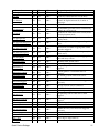
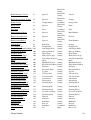
Binary Protocol
The following table offers a quick command reference for the A-MCB2. For convenience, you may sort the
table below by instruction name, command number, or reply number. Follow the links to view a detailed
description of each instruction or refer to the Binary Protocol Manual.
Reset
0
Ignored
Command
Type
Command
Home
1
Ignored
Command
Renumber*
Read Register
Set Active Register
Write Register
Move Tracking
Limit Active
Manual Move Tracking
Manual Move
Slip Tracking
Unexpected Position
Store Current Position*
Return Stored Position
Move To Stored Position
Move Absolute
Move Relative
Move At Constant Speed
Stop
Restore Settings*
Set Microstep Resolution*
Set Running Current*
Set Hold Current*
Set Device Mode*
Set Home Speed*
Set Target Speed*
Set Acceleration*
Set Maximum Position*
Set Current Position
Set Home Offset*
Set Alias Number*
Return Device Id
2
5
6
7
8
9
10
11
12
13
16
17
18
20
21
22
23
36
37
38
39
40
41
42
43
44
45
47
48
50
Ignored
Register Address
Register Address
Data
n/a
n/a
n/a
n/a
n/a
n/a
Address
Address
Address
Absolute Position
Relative Position
Speed
Ignored
Peripheral Id
Microsteps
Value
Value
Mode
Speed
Speed
Acceleration
Range
New Position
Offset
Alias Number
Ignored
Command
Command
Setting
Command
Reply
Reply
Reply
Reply
Reply
Reply
Command
Command
Command
Command
Command
Command
Command
Command
Setting
Setting
Setting
Setting
Setting
Setting
Setting
Setting
Setting
Setting
Setting
Instruction Name
Binary Protocol
Command#
Command Data
Reply Data
None
Final position (in this
case 0)
Device Id
Data
Register Address
Data
Tracking Position
Final Position
Tracking Position
Final Position
Tracking Position
Final Position
Address
Stored Position
Final Position
Final Position
Final Position
Speed
Final Position
Peripheral Id
Microsteps
Value
Value
Mode
Speed
Speed
Acceleration
Range
New Position
Offset
Alias Number
Device Id
23
Return Firmware Version
51
Ignored
Return Power Supply Voltage
52
Ignored
Return Setting
53
Setting Number
Return Status
54
Ignored
Echo Data
55
Data
Return Firmware Build
56
Ignored
Return Current Position
60
Ignored
Return Serial Number
63
Ignored
Set Park State*
65
Set Peripheral Id*
66
Set Auto-Reply Disabled Mode* 101
Set Message Id Mode*
102
Set Home Status
103
Set Home Sensor Type*
104
Set Auto-Home Disabled
105
Mode*
Set Minimum Position*
106
Set Knob Disabled Mode*
107
Set Knob Direction*
108
Set Knob Movement Mode*
109
Set Knob Jog Size*
110
Set Knob Velocity Scale*
111
Set Knob Velocity Profile*
112
Set Acceleration Only*
113
Set Deceleration Only*
114
Set Move Tracking Mode*
115
Set Manual Move Tracking
116
Disabled Mode*
Set Move Tracking Period*
117
Set Closed-Loop Mode*
118
Set Slip Tracking Period*
119
Set Stall Timeout*
120
Set Device Direction*
121
Set Baud Rate*
122
Set Protocol*
123
Convert To Ascii*
124
Error
255
Binary Protocol
Park State
Peripheral Id
Auto-Reply Mode
Message Id Mode
Home Status
Home Sensor Type
Auto-Home Disabled
Mode
Minimum Position
Knob Disabled Mode
Direction
Movement Mode
Jog Size
Velocity Scale
Velocity Profile
Acceleration
Deceleration
Tracking Mode
Read-Only
Setting
Read-Only
Setting
Read-Only
Setting
Command
Read-Only
Setting
Command
Read-Only
Setting
Read-Only
Setting
Read-Only
Setting
Setting
Setting
Setting
Setting
Setting
Setting
Version
Voltage
Setting Value
Status
Data
Build Number
Position
Serial Number
Setting
Setting
Setting
Setting
Setting
Setting
Setting
Setting
Setting
Setting
Position
Peripheral Id
Auto-Reply Mode
Message Id Mode
Home Status
Home Sensor Type
Auto-Home Disabled
Mode
Minimum Position
Knob Disabled Mode
Direction
Movement Mode
Jog Size
Velocity Scale
Velocity Profile
Acceleration
Deceleration
Tracking Mode
Tracking Mode
Setting
Tracking Mode
Tracking Period
Closed-Loop Mode
Tracking Period
Timeout
Direction
Baud Rate
Protocol
Baud Rate
n/a
Setting
Setting
Setting
Setting
Setting
Setting
Setting
Command
Reply
Tracking Period
Closed-Loop Mode
Tracking Period
Timeout
Direction
Baud Rate
Protocol
Baud Rate
Error Code
Setting
24
* The settings for these commands are saved in non-volatile memory, i.e. the setting persists even if the
device is powered down. To restore all settings to factory default, use command 36.
Binary Protocol
25
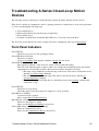
Troubleshooting A-Series Closed-Loop Motion
Devices
The following sections contain tips for troubleshooting common problems with the A-Series devices.
If the device is unable to communicate, and it is operating erratically, a manual factory reset can be performed
as a last resort through the following steps:
1. Power Off the device
2. Push and hold the knob for the first Axis (if applicable)
3. Power On the device
4. Continue to hold the knob in until the Blue LED is lit (~5 seconds), release the knob.
The device has been returned to its factory defaults and can be configured per the steps in Initial Setup.
Front Panel Indicators
Green LED On
The device is powered on and operating normally
Green LED Fades In and Out
The device is parked.
Issue a tools parking (T:65) unpark command, or home (T:1) the device.
Green LED Flashes Slowly
The operating conditions of the device are outside of the recommended range.
This will occur when the supply voltage is either over or under the recommended range, the internal
temperature has exceeded the set limit or the driver has disabled. Check the following:
◊ The input voltage within the operational range of the device. This can be read from the device
with the get system.voltage command.
◊ The device temperature is within range. This can be read from the device with the get
system.temperature command.
◊ The driver is not disabled. If the driver is disabled the result of the warnings command will
contain the FD flag.
Green LED Off
The device is not powered.
Check the supply connections and power adaptor for correct operation.
Red LED On or Flashing.
A critical error has occurred.
Please contact Zaber Technical Support.
Blue LED On or Flashing.
The device has slipped or stalled.
Please see the Slipping and Stalling section below.
Yellow LED Always Off or Flashes but No Reply.
There are communication errors.
Please see the Communication Errors section below.
Troubleshooting A-Series Closed-Loop Motion Devices
26
Manual Control
Turning the knob either way results in no movement
The knob may have been disabled.
Check that the knob.enable (T:107) setting is correct.
Restore the default parameters through the system restore (T:36) command.
The device won't cover the full range of travel.
The device hasn't been homed.
Turn the knob anti-clockwise until the device reaches the fully retracted position (closest to the
motor). The device will home and the full range of travel available.
Unexpected Behaviour
The device doesn't respond to a move command.
The device needs to be homed before use.
Send the home (T:1) command.
The device is moving on its own and running against the ends of travel.
The position encoder has de-synchronized.
Reset the device by power cycling it or sending system reset (T:0) command, then re-initialize it with
the home (T:1) command. Ground the device and avoid operation under a statically noisy
environment.
The device is moving very slowly. It used to move faster.
The speed settings may have been changed inadvertently.
Send a system restore (T:36) command.
The device makes louder than normal noise during travel and is frequently slipping.
This condition happens if the thrust needed is more than the thrust available from the device.
Check the following:
◊ The force on the device is less than the maximum thrust.
◊ The voltage using the get system.voltage command. Voltage less than the specified voltage
for the device will reduce the device’s maximum thrust.
Test the following:
◊ Try a slower target velocity. Stepper motors produce more thrust when moving slowly.
◊ Try a lower acceleration and deceleration.
◊ Clean the screw and lightly re-grease it with a grease that does not degrade plastics.
The device has repeatability errors smaller than 4 full steps.
If steps aren't being skipped, friction or loose parts may still cause some variation when returning to a
position.
Please contact Zaber Technical Support.
The device doesn't cover the full range of travel, or runs into the end.
A setting might have been inadvertently changed.
◊ home (T:1) the device to see if this corrects the behaviour.
◊ Send a system restore (T:36) command. Ensure that the periid setting of the devices
corresponds to the attached device. A list of peripheral ids are available at the Peripheral Ids
page.
Communication Errors
There is no communication with the device, the Yellow LED does not come on or flash.
Manual Control
27
There are several things should be checked:
◊ Make sure the correct serial port is selected. Try selecting other serial ports in the software.
◊ Check the baud rate, hand shaking, parity, stop bit, etc. when configuring the serial
communications software. The required settings are listed in the RS232 Communications
section above.
◊ Make sure there are no bent pins in the ends of all the data cables
◊ Make sure the device is powered, the Green LED should be on.
◊ If the computer is a laptop running on batteries, try plugging in the power. Some laptops
disable the serial ports when running on batteries.
◊ Make sure a null modem adaptor or cable is not being used.
◊ Make sure the correct adaptors(if any) are being used. Refer to the pinouts in the RS232
Communications section above.
◊ If the problem encountered when trying to control the device with custom software, try using
one of the demo programs from the Zaber website to verify that the hardware is functioning
properly.
The yellow light comes on briefly when sending a command, but the device does not move and does not
reply.
Check baud rate, hand shaking, parity, stop bit, etc. are set as per the RS232 Communications
defaults.
The device numbers may not be what is expected, issue a system renumber (T:2) command. Make
sure that the computer does not transmit anything else while the devices renumber.
If using the binary protocol, check the following:
◊ 6 bytes are transmitted and that the device number and command are valid.
◊ The software does not transmit any control characters such as line feed and spaces.
◊ That the serial port is not configured with a termination character (it often defaults to
linefeed).
If problems are encountered when using custom software, try using one of the demo programs from
the Zaber website to verify that the hardware works.
The device does not behave as expected when software sends it a series of commands.
The computer might be set to Unicode. This is common for languages that use non-Latin based
characters. Go to Control Panel/Regional and Language Options/Advanced. Select a language for
non-unicode programs. This should be English or another Latin based character language.
Check what is being sent out of the serial port. stackoverflow.com has a list of some tools to monitor
serial ports.
In Binary mode, the device does not send replies but otherwise works.
Auto-reply might have been disabled via T:101.
Send a system restore (T:36) command.
If the problem is encountered when trying to control the device with custom software:
◊ Use a demo program from the Zaber website to verify that the hardware is functioning
properly.
◊ Make sure that the receiving part of the code or commercial package is correct.
◊ Check the serial port settings are correct.
◊ Check connectors for bent or broken pins.
In Binary mode, the device sometimes returns fewer than 6 bytes.
This typically indicates a problem with the serial port settings. Some serial ports are set to
automatically recognize and remove specific control characters such as carriage returns when they
appear in the RS232 receive buffer.
Check the settings are correct and not removing or replacing characters.
Communication Errors
28
Slipping and Stalling
The device moves smoothly, but only moves for a short time then stops. The blue LED is flashing but the
device is not actually slipping or stalling
The internal encoder counter needs to be re-initialized. Reset the device by power cycling it or
sending system reset (T:0) command, then re-initialize it with the home (T:1) command.
Ground the device and avoid operating it under statically noisy environment.
The device makes noise but does not move. Blue LED is flashing.
The device is stalling.
Try removing all external loads. If the device now extends and retracts normally, the problem is
excessive load. Try to reduce the load and ensure the load is less than the maximum thrust. A higher
thrust or torque can be achieved by lowering the speed of the device using the maxspeed (T:42)
setting.
If a device is stalling with no external load at default speed and acceleration settings then it requires
servicing.
Slipping and Stalling
29
Warranty and Repair
For Zaber's policies on warranty and repair, please refer to the Ordering Policies
Standard products
Standard products are any part numbers that do not contain the suffix ENG followed by a 4 digit number.
Most, but not all, standard products are listed for sale on our website. All standard Zaber products are backed
by a one-month satisfaction guarantee. If you are not satisfied with your purchase, we will refund your
payment minus any shipping charges. Goods must be in brand new saleable condition with no marks. Zaber
products are guaranteed for one year. During this period Zaber will repair any products with faults due to
manufacturing defects, free of charge.
Custom products
Custom products are any part numbers containing the suffix ENG followed by a 4 digit number. Each of these
products has been designed for a custom application for a particular customer. Custom products are
guaranteed for one year, unless explicitly stated otherwise. During this period Zaber will repair any products
with faults due to manufacturing defects, free of charge.
How to return products
Customers with devices in need of return or repair should contact Zaber to obtain an RMA form which must
be filled out and sent back to us to receive an RMA number. The RMA form contains instructions for packing
and returning the device. The specified RMA number must be included on the shipment to ensure timely
processing.
Warranty and Repair
30
Email Updates
If you would like to receive our periodic email newsletter including product updates and promotions, please
sign up online at www.zaber.com (news section). Newsletters typically include a promotional offer worth at
least $100.
Email Updates
31
Contact Information
Contact Zaber Technologies Inc by any of the following methods:
Phone 1-604-569-3780 (direct)
1-888-276-8033 (toll free in North America)
Fax 1-604-648-8033
Mail #2 - 605 West Kent Ave. N., Vancouver, British Columbia, Canada, V6P 6T7
Web www.zaber.com
Email Please visit our website for up to date email contact information.
The original instructions for this product are available at http://www.zaber.com/wiki/Manuals/A-MCB2.
Contact Information
32
Appendix A - Available Communications Ports
Finding Installed Serial Ports
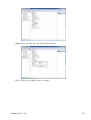
Windows
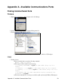
1. Right click on Computer or My Computer and select Manage.
2. Select Device Manager from the Computer Management list
3. Expand the Ports (COM & LPT) category
♦ In this example there is one serial port installed (COM1), which is a USB adaptor.
Linux
1. Finding devices
♦ Open a terminal and execute the following command:
dmesg | grep -E ttyU\?S↵
♦ The response will be similar to the following:
[ 2.029214] serial8250: ttyS0 at I/O 0x3f8 (irq = 4) is a
16550A
[ 2.432572] 00:07: ttyS0 at I/O 0x3f8 (irq = 4) is a 16550A
[ 2.468149] 0000:00:03.3: ttyS4 at I/O 0xec98 (irq = 17) is a
16550A
[ 13.514432] usb 7-2: FTDI USB Serial Device converter now
attached to ttyUSB0
♦ This shows that there are 3 serial ports available: ttyS0, ttyS4 and ttyUSB0 (a USB adaptor)
Appendix A - Available Communications Ports
33
2. Checking port permissions
♦ Using the ports found above, execute the following command
ls -l /dev/tty{S0, S4, USB0}↵
♦ The permissions, given below, show that a user has to be root or a member of the dialout
group to be able to access these devices
crw-rw---- 1 root dialout 4, 64 Oct 31 06:44 /dev/ttyS0
crw-rw---- 1 root dialout 4, 68 Oct 31 06:45 /dev/ttyS4
crw-rw---- 1 root dialout 188, 0 Oct 31 07:58 /dev/ttyUSB0
3. Checking group membership
groups↵
♦ The output will be similar to the following:
adm cdrom sudo dip plugdev users lpadmin sambashare
Notice that dialout is not in the list
♦ A user can be added to the dialout group with the following command
sudo adduser $USER dialout↵
♦ Group membership will not take effect until the next logon.
Linux
34
Appendix B - USB Driver Installation
Integrated USB on a Zaber Controller
Compatible Devices
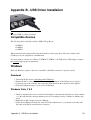
The following Zaber controllers include a USB 2.0 Type-B port:
• X-MCB1
• X-MCB2
• A-MCB2
When connected and configured following the instructions on this page, they will create a virtual serial
(COM) port on your computer for communication.
If you are trying to connect one of Zaber's X-USBDC, T-USBDC, or T-USB serial to USB adaptors, return to
the software support page for instructions.
Windows
Microsoft Windows requires a driver to be installed for the USB connection to operate correctly.
Download
1. Download the driver here: Zaber Integrated USB Driver.
2. Extract the files to a handy location: Downloads, My Documents or the Desktop are good places.
3. Connect power to the controller and connect the USB cable from the controller to the computer.
4. Follow the additional steps for your version of Windows.
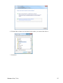
Windows Vista, 7 & 8
1. Windows will detect the device connection and attempt to automatically install drivers. After a minute
or so this will fail with a message that the device is not working correctly. Continue on with the steps
below.
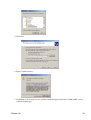
2. Right click on My Computer and select Manage.
3. Select Device Manager from the list on the left. Under 'Other devices', you should see an entry with
the name of the Zaber controller that is connected.
Appendix B - USB Driver Installation
35
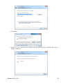
4. Right click on this entry and select 'Update Driver Software...'
5. Choose 'Browse my computer for driver software'.
Windows Vista, 7 & 8
36
6. Click the Browse button and select the location where you extracted the driver to.
7. Click Next.
Windows Vista, 7 & 8
37
8. Click Install.
9. Click Close. Your controller is now available and should appear in the Ports (COM & LPT) section of
the Device Manager.
Windows Vista, 7 & 8
38
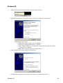
Windows XP
1. Windows will automatically detect the connection of the controller.
2. Once the New Hardware Found wizard starts, select 'No, not this time' and click next.
If the wizard doesn't start:
1. Right click on My Computer and select Manage.
2. Select Device Manager from the list on the left.
3. Under 'Unknown Devices', you should see an entry with the name of the Zaber
controller that is connected.
4. Right click on this entry and select 'Update Driver'.
3. Select 'Install from a specific location' and click Next.
4. Click the Browse button and select the location where you extracted the driver to.
Windows XP
39
5. Click Next.
6. Select Continue Anyway.
7. Click Finish. Your controller is now available and should appear in the Ports (COM & LPT) section
of the Device Manager.
Windows XP
40
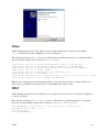
Linux
USB Communications Device Class (CDC) devices are supported in kernel 2.4 and above through the
cdc_acm module. No special configuration or drivers are needed.
The controller will appear as a ttyACMx device. The kernel log (available through dmesg) details the device
detection and the assigned device, in this case /dev/ttyACM0
[94929.668171]
[94929.686563]
[94929.686572]
[94929.686577]
[94929.686581]
[94929.686585]
[94929.687436]
[94929.687471]
usb 3-4.1.3: new full-speed USB device number 92 using xhci_hcd
usb 3-4.1.3: New USB device found, idVendor=2939, idProduct=cafe
usb 3-4.1.3: New USB device strings: Mfr=1, Product=2, SerialNumber=3
usb 3-4.1.3: Product: X-MCB2
usb 3-4.1.3: Manufacturer: Zaber Technologies Inc.
usb 3-4.1.3: SerialNumber: 1
cdc_acm 3-4.1.3:1.0: This device cannot do calls on its own. It is not a modem.
cdc_acm 3-4.1.3:1.0: ttyACM0: USB ACM device
Note: In some configurations, modem manager will try to query the device when it is connected. This won't
affect device operation but can cause the port to be unavailable for several seconds.
OS X
USB Communications Device Class (CDC) devices are supported in 10.5 and above. No special configuration
or drivers are needed.
The controller will appear as a tty.usbmodem device. The kernel log (available through dmesg) details
the device detection and the assigned device, in this case /dev/tty.usbmodem1421
AppleUSBCDCACMData: Version number - 4.1.23, Input buffers 8, Output buffers 16
AppleUSBCDC: Version number - 4.1.23
$ ls /dev/tty.usb*
/dev/tty.usbmodem1421
Linux
41
Appendix C - I/O Usage and Examples
The A-MCB2 controller features a range of flexible input and output options that can be easily examined and
controlled from user software. The input and output capabilities of the A-MCB2 can also be used with triggers
to perform actions based on the current value of the i/o channel.
NOTE: The A-MCB2 I/O features are only available when communicating with the ASCII Protocol.
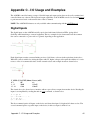
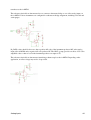
Digital Inputs
The digital inputs on the A-MCB2 are fully optoisolated and feature bidirection LEDs, giving added
flexibility when interfacing to external equipment. The two examples below demonstrate how the common
line can be connected to a power rail or to ground, depending on the application.
Each digital input contains a current limiting resistor of 442 ohms, as shown in the equivalent circuit above.
While this value is suitable for driving the inputs with 5V, higher voltages will require the addition of a series
resistor. A list of recommended values for the external resistor and example circuit are shown below.
V_SUPP (V) R_EXT (Ohms) Power (mW)
0 -8
0R
n/a
8 - 15
500R
125mW
15 - 24
1500
250mW
The circuit above also shows how to interface with an open collector output from another device. Reading the
inputs is accomplished by sending the unit an io get command, as shown below.
/1 io
@01 0
/1 io
@01 0
get di↵
OK IDLE –- 0 0 1 0
get di 1↵
OK IDLE -- 0
The first command queries all inputs on the device and shows that input 3 is high and all others are low. The
second command queries a specific input on the device, in this case input 1, which is low.
Appendix C - I/O Usage and Examples
42
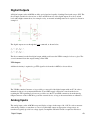
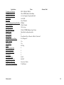
Digital Outputs
All digital outputs on the A-MCB2 are fully optoisolated and capable of sinking 15mA each at up to 50V. The
first example circuit below shows how to drive an LED from one of the digital outputs. In order to switch
loads with a higher current draw, for example a relay, an external switching transistor is required, as shown in
example 2.
The digital outputs are set through the io set command, as shown below.
/1 io
@01 0
/1 io
@01 0
set do 1 1↵
OK IDLE – 0
set do 1 0↵
OK IDLE – 0
The first command sets the first digital output, which would cause the LED in example 1 above to glow. The
second command clears the output, turning off the LED.
TTL Outputs
Additional circuitry is required to get TTL signal levels from the A-MCB2, as shown below.
The 74LS04 contains 6 inverters so its possible to convert all of the digital outputs with one IC. In order to
maintain isolation, it is recommended that the 5V and GND supply connections come from the device
requiring the TTL signalling. It is however possible to use the 5V and GND connections from the Analog
Output connector on the A-MCB2 to power the external device, as long as the current limits are adhered to.
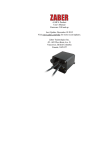
Analog Inputs
The analog inputs on the A-MCB2 accept and display voltages in the range of 0 – 10V. In order to measure
other analog variables, a transducer or sensor is required that outputs an appropriate voltage range. As
transducers typically provide low voltage signals, an amplifier and buffer circuit is required to interface a
Digital Outputs
43
transducer to the A-MCB2.
The reference circuit below demonstrates how to connect a wheatstone bridge to one of the analog inputs on
the A-MCB2. Various instruments are configured in a wheatstone bridge arragement, including load-cells and
strain guages.
R_GAIN's value should be chosen so that a positive full scale of the instrument produces 10V at the analog
input of the A-MCB2 and a negative full scale produces 0V. The OP97 op-amp provides an offset of 5V to the
amplified value so that no load on the instrument produces an output of 5V.
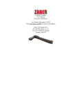
The reference circuit below demonstrates interfacing a thermocouple to the A-MCB2. Depending on the
application, an offset voltage may need to be provided.
Analog Inputs
44
Specification
Communication Interface
Communication Protocol
Maximum Current Draw
Power Supply
Power Plug
Controller Maximum Current Per Phase
Motor Connection
Default Resolution
Data Cable Connection
Manual Control
Axes of Motion
LED Indicators
Operating Temperature Range
RoHS Compliant
CE Compliant
Weight
Limit Sensors per Axis
Isolated Digital Input
Isolated Digital Output
Analog Input
Analog Input Range
Analog Input Resolution
2D Primitives Supported
5 V Power Out Current Rating
Analog Inputs
Value
RS-232, RS-485, USB 2.0
Zaber ASCII (Default), Zaber Binary
motor and supply voltage dependent mA
24-48 VDC
Screw Terminal
2500 mA
D-Sub 15 female
1/64 of a step
D-Sub 9, USB-B, Buchanan 4-pin 3.5 mm
Indexed knobs with push switches
2
Power, Error, Motor 1, Encoder 1, Motor 2, Encoder 2
0 to 50 degrees C
Yes
Yes
0.533 kg
4
4
4
4
0-10 V
0.0125 V
Lines, Arcs, Circles
Total 200 mA
Alternate Unit
45