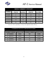
1
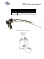
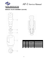
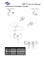
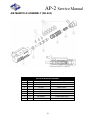
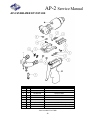
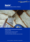
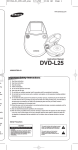
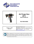
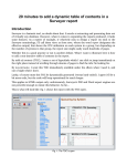
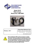
Air Purge Spray & Pour Gun AP-2 For use with non-flammable Foam and Polyurea For professional use only Not for use in explosive atmospheres Manual Ref. # MN-04006 PATENT PENDING Polyurethane Machinery Corp. REVISION 2.0 Corporate: 1 Komo Drive, Lakewood, NJ 08701 Manufacturing: 2 Komo Drive, Lakewood, NJ 08701 Phone: 732-415-4400 Fax: 732-364-4025 http://www.polymac-usa.com Before installing the AP-2 Gun and start-up, carefully read all the technical and safety documentation included in this manual. Pay special attention to the information in order to know and understand the operation and the conditions of use of the AP-2 Gun. All of the information is aimed at improving user safety and avoiding possible breakdowns from the incorrect use of the AP-2 Gun. AP-2 Service Manual Table of Contents WARRANTY ............................................................................................................................................. 4 SAFETY AND HANDLING ...................................................................................................................... 6 IMPORTANT SAFETY INFORMATION ........................................................................................... 7 CHARACTERISTICS ................................................................................................................................ 8 TECHNICAL SPECIFICATIONS ............................................................................................................. 8 GENERAL DESCRIPTION ....................................................................................................................... 9 INSTALLATION AND START UP ........................................................................................................ 10 SHUTDOWN PROCEDURES................................................................................................................. 12 LOSS OF AIR PRESSURE/EMERGENCY SHUT-OFF ........................................................................ 13 MAINTENANCE ..................................................................................................................................... 14 GUN BLOCK AND MIXING CHAMBER REMOVAL ................................................................ 14 SCREEN SCREW AND COMPONENT MAINTENANCE ........................................................... 16 AIR MANIFOLD MAINTENANCE .................................................................................................... 18 AIR CYLINDER MAINTENANCE .................................................................................................... 20 GUN OPERATION .................................................................................................................................. 22 TROUBLE SHOOTING GUIDE ............................................................................................................. 24 AP-2 CHAMBER KITS (GU-814-_ _ _)........................................................................................... 25 AP-2 PCT KITS (GU-815-_ _ _)....................................................................................................... 26 CHAMBER/PCT KIT (KT-814-_ _ _) ............................................................................................... 27 AIR MANIFOLD TRIGGER REBUILD KIT (KT-826) .................................................................... 28 AIR CYLINDER REBUILD KIT (KT-801) ........................................................................................ 28 AP-2 O-RING KIT (KT-827) .............................................................................................................. 28 PMC RECOMMENDED O-RING GREASE ................................................................................... 28 A & R SCREEN SCREW ASSEMBLY KITS (KT-819-_) ............................................................. 29 RECOMMENDED SPARE PARTS ................................................................................................. 29 SCREEN SIZES ................................................................................................................................. 30 OPTIONAL PARTS ............................................................................................................................ 30 CHECK VALVE ASSEMBLY (KT-850) ........................................................................................... 30 2 AP-2 Service Manual PARTS IDENTIFICATION ..................................................................................................................... 32 MANUAL VALVE ASSEMBLY (GU-020) ....................................................................................... 32 COUPLING BLOCK ASSEMBLY (GU-04001) .............................................................................. 33 AIR MANIFOLD ASSEMBLY (GU-843).......................................................................................... 34 END CAP ASSEMBLY (GU-844) .................................................................................................... 35 AIR CYLINDER ASSEMBLY (GU-801A) ....................................................................................... 36 COMPLETE AIR CYLINDER ASSEMBLY (GU-845) ................................................................... 37 AIR PURGE SPRAY AND POUR GUN (GU-850) ........................................................................ 38 SCREEN SCREW ASSEMBLY ....................................................................................................... 40 LIST OF TOOLS ................................................................................................................................. 41 APPENDIX ............................................................................................................................................... 42 GREASE GUN ASSEMBLY ............................................................................................................. 42 MIXING CHAMBER FLOW RATE* ................................................................................................. 43 CHAMBER/ORIFICE COMPARISON CHART .............................................................................. 43 TECHNICAL SERVICE BULLETIN ................................................................................................. 44 MANUAL REVISIONS ........................................................................................................................... 49 3 AP-2 Service Manual WARRANTY Polyurethane Machinery Corporation (hereinafter “PMC”) provides this LIMITED WARRANTY (hereinafter “Warranty”) to the original purchaser (hereinafter “Customer”) covering this equipment and the original PMC manufactured accessories delivered with the equipment (hereinafter “Product”) against defects in material or workmanship of the Product (hereinafter “Defect” or “Defective”) for a period of one (1) year from the date of first purchase as shown on the original PMC invoice (hereinafter “Warranty Period”). If during the Warranty Period under normal use, the Product is suspected by Customer to be Defective in material or workmanship, it is Customer’s responsibility to contact PMC and return the Product to PMC as directed by PMC, freight prepaid. If PMC determines that the Product is Defective and that such Defect is covered by this Warranty, PMC will credit Customer for the reasonable freight charges incurred by Customer in returning the Defective Product to PMC, and PMC (or its authorized agent) will, at PMC’s option, repair or replace the Product, subject to the following: Original Invoice: The original invoice must be kept as proof of the date of first sale and the Product serial number. The Warranty does not cover any Product if the Original Invoice appears to have been modified or altered, or when the serial number on the Product appears to have been altered or defaced. Product Maintenance: It is the Customer’s responsibility to maintain the Product properly. See your maintenance schedule and owner’s manual for details. The Warranty does not cover an improperly maintained Product. Non-PMC Components and Accessories: Non-PMC manufactured components and accessories that are used in the operation of the Product are not covered by this Warranty. Such components and accessories shall be subject to the warranty offered to the Customer, if any, by the original manufacturer of such component or accessory. Other Warranty Exclusions: The Warranty does not cover any Product that PMC determines has been damaged or fails to operate properly due to misuse, negligence, abuse, carelessness, neglect, or accident. By way of example only, this includes: Normal wear and tear. Improper or unauthorized installation, repair, alteration, adjustment or modification of the Product. Use of heating devices, pumping equipment, dispensers, or other parts or accessories with the Product that have not been approved or manufactured by PMC. Failure to follow the operating instructions and recommendations provided by PMC may cause loss or damage to personnel, equipment, or work area. Fire, flood, “acts of God,” or other contingencies beyond the control of PMC. 4 AP-2 Service Manual WARRANTY (cont’d) THE WARRANTY DESCRIBED HEREIN IS THE EXCLUSIVE REMEDY FOR THE CUSTOMER AND IS IN LIEU OF ALL OTHER WARRANTIES, EXPRESS, IMPLIED, STATUTORY O R O T H E R W I S E , A N D T H E I M P L I E D W A R R A N T I E S O F M E R C H A N T A B I L I T Y AND FITNESS FOR A PARTICULAR PURPOSE AND ALL OTHER WARRANTIES ARE HEREBY DISCLAIMED. TO THE FULLEST EXTENT PERMITTED BY LAW, PMC SHALL NOT BE RESPONSIBLE, WHETHER BASED IN CONTRACT, TORT (INCLUDING, WITHOUT LIMITATION, NEGLIGENCE), WARRANTY OR ANY OTHER LEGAL OR EQUITABLE GROUNDS, FOR ANY CONSEQUENTIAL, INDIRECT, INCIDENTAL, LOST PROFITS, SPECIAL, PUNITIVE OR EXEMPLARY DAMAGES, WHETHER TO PERSON OR PROPERTY, ARISING FROM OR RELATING TO THE PRODUCT, EVEN IF PMC HAS BEEN ADVISED OF THE POSSIBILITY OF SUCH LOSSES OR DAMAGES. Non-Warranty Service by PMC: If PMC determines that the suspected Defect of the Product is not covered by this Warranty, disposition of the Product will be made pursuant to the terms and conditions of PMC’s written estimate on a time and materials basis. Continuing Warranty for Products Repaired or Replaced under Warranty: Following the repair or replacement of a Product covered by this Warranty, such Product will continue to be subject to the original Warranty for the remainder of original Warranty Period or for three (3) months from the repair or replacement date, whichever is longer. No Rights Implied: Nothing in the sale, lease or rental of any Product by PMC shall be construed to grant any right, interest or license in or under any patent, trademark, copyright, trade secret or other proprietary right or material owned by anyone; nor does PMC encourage the infringement of same. Exclusive Warranty: This writing is the final, complete, and exclusive expression of the Warranty covering the Product. Any statements made by PMC, its employees or agents that differ from the terms of this Warranty shall have no effect. It is expressly understood that Customer’s acceptance of this Warranty, by performance or otherwise, is upon and subject solely to the terms and conditions hereof, and any additional or different terms and conditions proposed or expressed by Customer or anyone, whether in writing or otherwise, are null and void unless specifically agreed to in writing by an Officer of PMC. 5 AP-2 Service Manual SAFETY AND HANDLING This chapter contains important information on the safety, handling and use of your AP-2 series Gun. READ THIS MANUAL BEFORE OPERATING THIS EQUIPMENT. FAILURE TO FULLY READ AND UNDERSTAND THIS MANUAL MIGHT RESULT IN DAMAGE OR LOSS TO PERSONNEL, EQUIPMENT, OR PROPERTY. WARNING! Presents information to alert of a situation that might cause serious injuries if the instructions are not followed. CAUTION! Presents information that indicates how to avoid damage to the AP-2 Gun or how to avoid a situation that could cause injuries. NOTE: Is relevant information of a procedure being carried out. Careful study of this Manual will enable the operator to know the characteristics of the Gun and the operating procedures. By following the instructions and recommendations contained, you will reduce the potential risk of accidents in the installation, use or maintenance of the AP-2 Gun; you will provide a better opportunity for incident-free operation for a longer time, greater productivity and the possibility of detecting and resolving problems fast and simply. Keep this Service Manual for future reference to useful information. If you lose this Manual, ask for a new copy from your PMC Service Center, go to the company website (www.polymac-usa.com), or directly contact Polyurethane Machinery Company. 6 AP-2 Service Manual IMPORTANT SAFETY INFORMATION The AP-2 Gun has been designed and built for the application of polyurea chemical systems, polyurethane foam chemical systems and some two-component epoxy systems. WARNING! The design and configuration of the AP-2 Gun does not allow its use in potentially explosive atmospheres or exceeding the pressure and temperature limits described in the Technical Specifications of this Manual to be exceeded. Always use liquids and solvents that are compatible with the AP-2 Gun. If in doubt, consult PMC Technical Service. When working with the AP-2 Gun, it is recommended that the operator wear suitable clothing and elements of personal protection, including, without limitation, gloves, protective goggles, safety footwear and face masks. Use breathing equipment when working with the Gun in enclosed spaces or in areas with insufficient ventilation. The introduction and follow-up of safety measures must not be limited to those described in this Manual. Before beginning to work with the Gun, a comprehensive analysis must be made of the risks derived from the products to be dispensed, the type of application and the working environment. To prevent possible injury caused by incorrect handling of the materials and solvents used in the process, carefully read the Material Safety Data Sheet (MSDS) provided by your supplier. To avoid damage caused by the impact of pressurized fluids, do not open any connection or perform maintenance work on components subject to pressure until the pressure has been completely eliminated. Use suitable protection when operating, maintaining or being present in the area where the equipment is functioning. This includes, but is not limited to, the use of protective goggles, gloves, shoes and safety clothing and breathing equipment. The equipment includes components that reach high temperatures and can cause burns. Hot parts of the equipment must not be handled or touched until they have cooled completely. The equipment sprays high pressure fluids that can lead to fluid being injected under the skin or eyes. Severe injury could be incurred. Proper personal protective equipment should be used in conjunction with training and situational awareness of all personnel on the job. 7 AP-2 Service Manual CHARACTERISTICS Internal mixing from high pressure impingement Automatic cleaning with air pressure No solvents required Exterior lubrication of the Mix Chamber Weight: 2.235 lbs (1.012 kg) (w/o coupling block) 2.302 lbs (1.317kg) (with coupling block) TECHNICAL SPECIFICATIONS Maximum Working Pressure: _______________________________ 3,500 psi (245 Bar) Air Pressure: __________________________________________________90-125 psi (6.2-8.6 Bar) Maximum Output (1:1 ratio): ____________________________________ 40 lb/min (20 L/min) Minimum Output (1:1 ratio):____________________________________ 3.3 lb/min (1.55 L/min) Opening Force @ 110 psi (8 Bar): ____________________________________ 200 lb (91 kg) Closing Force @ 110 psi (8 Bar): __________________________________________ 200 lb (91 kg) 8 AP-2 Service Manual GENERAL DESCRIPTION For better knowledge of the AP-2 Gun, the main components and their description are shown. For a more precise identification, see the Parts Identification section. ITEM 1b 1c 2 2b 3 3d 4 5 6b 9 10 12 13 20 9 QTY 1 1 1 1 1 2 2 2 2 1 1 1 1 1 1 1 1 AP-2 GENERAL DESCRIPTION PART NUMBER DESCRIPTION GU-801 Air Cylinder GU-804 Gun Lock and End Cap GU-816 Gun Block GU-837 Grease Fitting GU-802 Piston GU-020 Manual Valves GU-851 Check Valve Seat GU-852 Check Valve Spring GU-853 ¼” Check Valve Ball GU-04001 Coupling Block Assembly GU-812 Lock Collar GU-827-1 Gun Handle GU-828 Trigger GU-843 Air Manifold GU-842 Head Latch GU-819-A “A” Screen Screw GU-819-R “R” Screen Screw AP-2 Service Manual INSTALLATION AND START UP CAUTION! When working with the AP-2 Gun or performing maintenance work, wear suitable safety protection in accordance with the recommendations and specifications provided by the product suppliers. 1. Install Coupling Block (GU-04001) to the hose. 2. Ensure the Coupling Block Manual Valves (3d) are CLOSED by turning them to the full clockwise position. CAUTION! Excessive force closing or opening the Manual Valves may result in damage to the Manual Valves and/or Coupling Block. 3. Set the Gun Lock (1c) to the LOCKED position. 4. Ensure Check Valve Assemblies (4, Pg. 9) are in place. 5. Connect the Coupling Block (5) to the Gun Block (2) using the nut driver provided (TL-04001, Pg. 40). Tighten Coupling Block until there is a hand tight seal. 6. Connect air supply to the Gun (90 to 125 psi, 6.2 to 8.6 Bar). NOTE: The material delivery hoses are color coded Red and Blue, allowing the user to recognize them. The Red corresponds to the Isocyanate (A) and the Blue to the Polyol (R). To avoid connection errors, the Coupling Connections of the Isocyanate (A) and Polyol (R) hoses are also different sizes, which makes it difficult to swap connections. 7. Set the Gun Lock (1c) to the OPEN position. 8. Pull the Trigger (10) several times to check for correct movement of the Mixing Chamber (6, Pg. 14) and PCT (pattern control tip) (7). 10 AP-2 Service Manual 9. Ensure that the Proportioner and the supply system is in the ready position and the material pressures at the Proportioner and the material temperatures in the Material Heaters and Heated Hoses are set as recommended by the chemical supplier (see Machine Service Manual). 10. OPEN each Manual Valve (3d, Pg. 10) by turning three full turns counter clockwise. 11. Perform a test spray. 11 AP-2 Service Manual SHUTDOWN PROCEDURES 1. CLOSE the Manual Valves (3d) by turning them to the full clockwise position. CAUTION! Excessive force closing or opening Manual Valves may result in damage to the Manual Valves and/or Coupling Block. 2. Using the supplied Grease Gun (2, TL-00002, Pg. 40), lubricate the Mixing Chamber through the Grease Fitting (2b) until a fine mist of grease is sprayed from the gun (see page 42 for Grease Gun Assembly Instructions). This action will help prevent ISOCYANATE from crystallizing on the mixing chamber which may cause damage to the internal parts. Note: PMC Grease is recommended. Use of incorrect grease will cause blockage in the mixing chamber. 3. Disconnect the air supply. NOTE: The injection of grease supplied with the Gun at the end of the day will minimize maintenance time and eliminate the need to remove the Mixing Chamber each day to clean it. Use of grease with high moisture content will not achieve the desired results. 12 AP-2 Service Manual LOSS OF AIR PRESSURE/EMERGENCY SHUT-OFF 1. Shut off air supply to gun. 2. Using the palm of your hand, push in on the Gun Lock (1c) and rotate clockwise to set it to the LOCKED position. In the locked position the Gun Lock will restrict the movement of the air piston (center line) from moving to the rear to an open position, thus rendering the gun inoperable. 3. CLOSE each Manual Valve (3d). CAUTION! Excessive force closing or opening Manual Valves may result in damage to the Manual Valves and/or Coupling Block. Emergency shut off if trigger sticks – disconnect air line. 13 AP-2 Service Manual MAINTENANCE To obtain maximum performance from your AP-2 Gun, it is necessary to periodically perform certain maintenance operations WARNING! Before proceeding with any maintenance work on the AP-2 Gun, SHUT OFF/DISCONNECT the air supply, ensure the Gun Lock is in the LOCKED position and the Manual Valves are CLOSED. Trigger the Gun to remove internal material pressure. It is recommended to remove the Gun from the Coupling Block. GUN BLOCK AND MIXING CHAMBER REMOVAL 1. CLOSE the Manual Valves (3d) by turning them to the full clockwise position. CAUTION! Excessive force opening or closing Manual Valves may result in damage to the Manual Valves and/or Coupling Block. 14 AP-2 Service Manual 2. Trigger Gun over Waste Container to release internal material pressure. 3. Using the wrench provided (TL-09, Pg. 40) or a standard 5/8” wrench, remove the Pattern Control Tip (7, Pg. 14) from the mixing chamber. 4. Using a ½” wrench, loosen or remove both Screen Screws (20, Pg. 14) to facilitate easy removal of the mixing chamber. 5. Using the nut driver provided (TL-04001, Pg. 14), remove the Coupling Block (5, Pg. 14) from the Gun Block (2, Pg. 14). 6. Disengage the Head Latch (13, Pg. 14) from the Gun Block (5, Pg. 14). 7. Loosen the Locking Collar (6b) from the Gun Block (2, Pg. 14) and remove the Gun Block (2, Pg. 14) from the Air Cylinder (1b, Pg. 14). 8. Remove the Chamber from the Piston Rod (3a, Pg. 14). 9. Flush Gun Block (2, Pg. 14) to remove any residue. Use recommended Flush Tank (TL-12, Pg. 31). 10. Clean or replace the Mixing Chamber (6, Pg. 14) as required. 11. Reassemble the Mixing Chamber (6, Pg. 14) in reverse order. NOTE! A small amount of PMC grease applied to the Mixing Chamber (6, Pg. 14) and Side Seals (27, Pg. 16) upon assembly is recommended. CAUTION! Use wooden or plastic tools or a brass brush for cleaning. Do not use metal or abrasive tools that can scratch or damage the contact surfaces. 15 AP-2 Service Manual SCREEN SCREW AND COMPONENT MAINTENANCE ITEM QTY 1 22 1 23 1 1 24 1 1 25 1 26 1 27 1 28 1 29 1 SCREEN SCREW COMPONENTS PART NUMBER DESCRIPTION GU-819-A “A” SCREEN SCREW GU-819-R “R” SCREEN SCREW GU-04007 SCREEN SCREW SEAL GU-818-40 FILTER SCREEN; 40 MESH. SEE PAGE 30 GU-818-60 FILTER SCREEN; 60 MESH. SEE PAGE 30 GU-818-80 FILTER SCREEN; 80 MESH. SEE PAGE 30 (STANDARD) OR-801 O-RING #013 80D AFLAS OR-800 #013 BACK UP RING OR-00043B O-RING #010 80D AFLAS SP-04005 SPRING; SIDE SEAL GU-817-90 SIDE SEAL CAUTION! To avoid possible contamination by the residual chemical inside the Gun do not interchange the Isocyanate (A) parts with the Polyol (R) parts. The Isocyanate (A) side is identified with an (A) on the Screen Screw Head and the Polyol (R) side is marked with an (R) on the Screen Screw Head. The Gun Block is also marked with (A) and (R) designation. 1. CLOSE the Manual Valves (3d, Pg. 9) by turning them to the full clockwise position. 16 AP-2 Service Manual CAUTION! Excessive force opening or closing Manual Valves may result in damage to the Manual Valves and/or Coupling Block. 2. Trigger Gun over Waste Container to release internal material pressure. 3. SHUT OFF AIR SUPPLY TO GUN. 4. Set the Gun Lock (1c, Pg. 9) to the LOCKED position. 5. Use a ½” wrench to remove the Screen Screw (20). 6. To clean or replace the Screen (22), remove O-Ring (23) and Back Up Ring (24). 7. Remove the Side Seal (27) and Spring (26) from the Screen Screw. Inspect the components and O-rings. Clean or replace as required. 8. Inspect for damage and apply PMC lubrication to the O-rings and threads and reassemble in reverse order. 9. The Gun is now ready for service. NOTE: When replacing O-rings, replace ALL O-rings included in the appropriate Kit. 17 AP-2 Service Manual AIR MANIFOLD MAINTENANCE 1. CLOSE the Manual Valves (3d, Pg. 9) by turning them to the full clockwise position. CAUTION! Excessive force opening or closing Manual Valves may result in damage to the Manual Valves and/or Coupling Block. 2. Set the Gun Lock (1c, Pg. 9) to the LOCKED position. 3. Disconnect the air supply from the Gun. 4. Use a suitable size wrench and remove the air fitting from the rear of the manifold. 5. Remove the trigger from the assembly to access the front of the air manifold. 6. Use supplied wrench (TL-09, Pg. 40) and remove the spool valve retainer (6e). 7. Remove the Spring (5e), Spool Valve Liner (4e), Spool Valve (3e), and Liner Bushing (2e) using the tool provided (TL-10, Pg. 40). 8. Remove and discard O-Rings (7e & 8e) 9. Replace the O-rings (7e & 8e, Pg. 18) and Spring (5e, Pg. 18) supplied in KT-826 (Pg. 27). Extra PMC grease will facilitate reassembly. 18 AP-2 Service Manual NOTE! When replacing O-rings, replace ALL O-rings included in KT-826 Rebuild Kit. 10. Inspect, clean and/or replace all remaining assembly components. Apply a small amount of PMC grease to the inside of the manifold cavity and to the O-rings on the Spool Valve to facilitate reassembly. 11. Reattach the Trigger and Air Manifold assembly in reverse order. 19 AP-2 Service Manual AIR CYLINDER MAINTENANCE 1. CLOSE the Manual Valves (3d) by turning them to the full clockwise position. CAUTION! Excessive force opening or closing Manual Valves may result in damage to the Manual Valves and/or Coupling Block. 2. Trigger Gun over Waste Container to release internal material pressure. 3. Disconnect air supply to gun. 4. Set the Gun Lock (1c) to the LOCKED position. 5. Loosen the Screen Screws (20) using a ½” wrench. 6. Disconnect Coupling Block (5) from Gun Block (2) using the Nut Driver provided (TL-04001, Pg. 40). 7. Disengage the Head Latch (13) from the Gun Block (2). 8. Loosen the Locking Collar (6b) from the Gun Block (2) and remove the complete Gun Block assembly from the Air Cylinder (1a). 20 AP-2 Service Manual 9. Using the Wrench (TL-09, Pg. 40) provided, remove the End Cap (2a, Pg. 20). 10. Push on the exposed Piston (3a, Pg. 20) by the Locking Collar (6b, Pg. 20) to remove the Piston (3a, Pg. 20) from the rear of the Air Cylinder (1a, Pg. 20). 11. Inspect the O-rings (4a, 5a, Pg. 20) on the Piston and shaft and replace as required. 12. Inspect the O-ring on the End Cap (2a. Pg. 20) and replace as required. NOTE! When replacing O-rings, replace ALL Orings included in the KT-801 Rebuild Kit. 13. Coat the inside of the Cylinder and all O-rings with PMC grease to facilitate reassembly. 14. Reassemble the Air Cylinder in reverse order. CAUTION! Use wooden or plastic tools or a brass brush for cleaning. Do not use metal or abrasive tools that can scratch the contact surfaces. 21 AP-2 Service Manual GUN OPERATION Compressed Shop Air 90 – 120 PSI (6.2 – 8.3 Bar) TRIGGERED OFF Compressed shop air: Enters through the rear of the Air Manifold. Passes around the Spool Valve to the back of the Piston moving the Piston and Chamber forward to the CLOSED position and maintaining it closed. In the closed position, the orifices in the Chamber are not concealed within the Side Seal ports and are opened to the air/grease chamber in the Gun Block. Purge air passes through the spool valve and past a check valve and into the air cylinder and gun block. Purge air and residual grease enter the mixing chamber and pass through the chamber and PCT expelling mixed material out of the chamber area. Purge air is also expelled from the PCT in a circular trajectory to keep the tip clean. 22 AP-2 Service Manual GUN OPERATION Compressed Shop Air 90 – 120 PSI (6.2 – 8.3 Bar) TRIGGERED ON Compressed shop air passes through the open Spool Valve, filling the cavity and pushing the Piston and Chamber rearward. The orifices in the Chamber are now captured within the Side seal and exposed to high pressure chemical. High pressure chemical enters the chamber from the opposing orifices. The high pressure chemicals mix by impingement, and the mixture then travels down the chamber and out the PTC. NOTE! While the trigger is pulled, the purge air is shutoff during spraying and the PCT will be retracted to the point of being flush with the front surface of the Gun Block. 23 AP-2 Service Manual TROUBLE SHOOTING GUIDE PROBLEM POSSIBLE CAUSE Insufficient Gun air pressure (minimum 90 psi, 6.2 PCT not flush with Bar) Gun Block when Gun Trigger Valve requires service is triggered Air Passages plugged Lock is in “Locked” position Air supply is not on Material does not Manual Valve (3d) CLOSED spray when Gun is Mixing Chamber (6) Inlet Orifices plugged triggered Side Seal (27) Orifices plugged Check Valve (4) plugged Trigger Valve requires service Insufficient Gun air pressure (minimum 90 psi, 6.2 Mixing Chamber Bar) moves slowly Piston Assembly requires service Air Passages plugged Mixing Chamber moves slowly, then normal speed Side Seal (27) Orifices plugged SOLUTION Ensure 90 psi (6.2 Bar) of air pressure at Gun Rebuild, see page 18 Clean, See page 18 Unlock gun Turn on air supply OPEN, see page 10, #9 Clean, see page 14 Clean, see page 16 Replace, see page 37 Rebuild, see page 18 Ensure 90 psi (6.2 Bar) of air pressure Rebuild, see page 20 Clean, see page 22 Inspect Side Seals (27), Mixing Chamber (6) for reacted materials, clean, see pages 14,16 Adjust, see Proportioner Operating Manual Inspect and clean Inspect and clean Clean Clean, see page 16 Dirty screens Material temperatures not as recommended by material supplier Side Seal (27) damaged Mixing Chamber (6) damaged Side Seal/ Screen Screw O-rings (Pg 16) damaged Side Seal (27) damaged Mixing Chamber (6) damaged Side Seal/Screen Screw O-rings (Pg 16) damaged Replace Adjust, see Proportioner Operating Manual Replace, see page 16 Replace, see page 14 Replace, see page 16 Replace, see page 16 Replace, see page 14 Replace, see page 16 Reacted material around Side Seals (27) Incorrect chemical temperature Pattern deformation Material spray pressure imbalance Iso and/or Resin in Gun Air Passages Material mist from Mixing Chamber (3) or PCT (4) Mixing Chamber Nozzle dirty PCT dirty Mixing Chamber (6) Inlet Orifices plugged Adjust, see Proportioner Excessive overspray Material temperatures and/or spray pressures not as recommended by material supplier Operating Manual Buildup of material on PCT Steady air leakage from Handle Plugged air passages in PCT (7) and Gun Block (1) Clean, see page 22 Air Cylinder (1a) O-rings damaged Replace, see page 20 Trigger Valve O-rings damaged (8e) Replace, see page 18 24 AP-2 Service Manual REFERENCE GUIDE AP-2 CHAMBER KITS (GU-814-_ _ _) KIT NUMBER GU-814-000 GU-814-00 GU-814-01 GU-814-01X GU-814-02 GU-814-02X GU-814-03 GU-814-04 PART NUMBER QTY GU-03032 1 GU-03031 1 RM-814-000 1 GU-03023 1 GU-03027 1 RM-814-00 1 GU-03035 1 GU-03021 1 RM-814-01 1 GU-03053 1 GU-03052 1 RM-814-01X 1 GU-03024 1 GU-03023 1 RM-814-02 1 GU-03051 1 GU-03050 1 RM-814-02X 1 GU-03028 1 GU-03035 1 RM-814-03 1 GU-03029 1 GU-03054 1 RM-814-04 1 DESCRIPTION (INCH) #61 DRILL (.0390) #70 DRILL (.0280) CHAMBER #000 #56 DRILL (.0465) #69 DRILL (.0292) CHAMBER #00 #54 DRILL (.055) #59 DRILL (.0410) CHAMBER #01 #52 DRILL (.0635) #57 DRILL (.0430) CHAMBER #01X #51 DRILL (.0676) #56 DRILL (.0465) CHAMBER #02 #48 DRILL (.0760) #55 DRILL (.0520) CHAMBER #02X #44 DRILL (.0860) #54 DRILL (.055) CHAMBER #03 #43 DRILL (.0890) #50 DRILL (.0700) CHAMBER #04 FOR USE WITH ILLUSTRATION MIXING NOZZEL MIXING CHAMBER PORT - - MIXING NOZZEL MIXING CHAMBER PORT - - MIXING NOZZEL MIXING CHAMBER PORT - - MIXING NOZZEL MIXING CHAMBER PORT - - MIXING NOZZEL MIXING CHAMBER PORT - - MIXING NOZZEL MIXING CHAMBER PORT - - MIXING NOZZEL MIXING CHAMBER PORT - - MIXING NOZZEL MIXING CHAMBER PORT - 25 - AP-2 Service Manual AP-2 PCT KITS (GU-815-_ _ _) KIT NUMBER PART NUMBER GU-03033 QTY DESCRIPTION FOR USE WITH 1 #65 DRILL (.0350) PCT PURGE PORT GU-03035 1 #54 DRILL (.055) GU-03032 1 #61 DRILL (.0390) PCT PURGE PORT PCT NOZZEL PORT OR-00042A 1 PCT FLAT TIP O-RING .016 - RM-815-000 1 PATTERN CONTROL TIP 000 - GU-03033 1 #65 DRILL (.0350) PCT PURGE PORT GU-03035 1 #54 DRILL (.055) GU-03023 1 #56 DRILL (.0465) PCT PURGE PORT PCT NOZZEL PORT OR-00042A 1 PCT FLAT TIP O-RING .016 - RM-815-00 1 PATTERN CONTROL TIP 00 - GU-03033 1 #65 DRILL (.0350) GU-03035 2 #54 DRILL (.055) OR-00042A 1 PCT FLAT TIP O-RING .016 - RM-815-01 1 PATTERN CONTROL TIP 01 - GU-03033 1 #65 DRILL (.0350) PCT PURGE PORT GU-03035 1 #54 DRILL (.055) PCT PURGE PORT PCT NOZZEL PORT GU-815-000 GU-815-00 GU-815-01 GU-03051 #52 DRILL (.0635) GU-815-01X PCT PURGE PORT PCT PURGE & NOZZEL PORT OR-00042A 1 PCT FLAT TIP O-RING .016 - RM-815-01X 1 PATTERN CONTROL TIP 01X - GU-03033 1 #65 DRILL (.0350) PCT PURGE PORT GU-03035 1 #54 DRILL (.055) GU-03024 1 #51 DRILL (.0676) PCT PURGE PORT PCT NOZZEL PORT OR-00042A 1 PCT FLAT TIP O-RING .016 - RM-815-02 1 PATTERN CONTROL TIP 02 - GU-03033 1 #65 DRILL (.0350) PCT PURGE PORT GU-03035 1 #54 DRILL (.055) GU-03051 1 #46 DRILL (.0810) PCT PURGE PORT PCT NOZZEL PORT OR-00042A 1 PCT FLAT TIP O-RING .016 - RM-815-02X 1 PATTERN CONTROL TIP 02X - GU-815-02 GU-815-02X 26 ILLUSTRATION AP-2 Service Manual AP-2 PCT KITS (GU-815-_ _ _) CONTINUED GU-03033 1 #65 DRILL (.0350) PCT PURGE PORT GU-03035 1 #54 DRILL (.055) GU-030-28 1 #44 DRILL (.0860) PCT PURGE PORT PCT NOZZEL PORT OR-00042A 1 PCT FLAT TIP O-RING .016 - RM-815-03 1 PATTERN CONTROL TIP 03 - GU-03033 1 #65 DRILL (.0350) PCT PURGE PORT GU-03035 1 #54 DRILL (.055) GU-03029 1 #43 DRILL (.0935) PCT PURGE PORT PCT NOZZEL PORT OR-00042A 1 PCT FLAT TIP O-RING .016 - RM-815-04 1 PATTERN CONTROL TIP 04 - GU-815-03 GU-815-04 CHAMBER/PCT KIT (KT-814-_ _ _) KIT NUMBER KT-814-000 KT-814-00 KT-814-01 KT-814-01X KT-814-02 KT-814-02X KT-814-03 KT-814-04 PART NUMBER QTY DESCRIPTION GU-814-000 1 CHAMBER 000 W/ DRILLS GU-815-000 1 PCT 000 RND W/ DRILLS GU-814-00 1 CHAMBER 00 W/ DRILLS GU-815-00 1 PCT 00 RND W/ DRILLS GU-814-01 1 CHAMBER 01 W/ DRILLS GU-815-01 1 PCT 01 RND W/ DRILLS GU-814-01X 1 CHAMBER 01X W/ DRILLS GU-815-01X 1 PCT 01X RND W/ DRILLS GU-814-02 1 CHAMBER 02 W/ DRILLS GU-815-02 1 PCT 02 RND W/ DRILLS GU-814-02X 1 CHAMBER 02X W/ DRILLS GU-815-02X 1 PCT 02X RND W/ DRILLS GU-814-03 1 CHAMBER 03 W/ DRILLS GU-815-03 1 PCT 03 RND W/ DRILLS GU-814-04 1 CHAMBER 04 W/ DRILLS GU-815-04 1 PCT 04 RND W/ DRILLS 27 AP-2 Service Manual AIR MANIFOLD TRIGGER REBUILD KIT (KT-826) PART NUMBER QTY DESCRIPTION GU-825-1 1 SPOOL VALVE LINER GU-825-2 1 LINER BUSHING GU-824 1 SPOOL VALVE SPRING OR-803 7 O-RING #012 VITON OR-00002A 3 O-RING #008 VITON OR-804 1 O-RING 2MMX4MM BUNA OR-00037B 2 QUAD RING #011 VITON AIR CYLINDER REBUILD KIT (KT-801) PART NUMBER QTY DESCRIPTION OR-00026A 2 O-RING #129 VITON OR-00043A 3 O-RING #010 80D AFLAS OR-00002A 1 O-RING #008 VITON OR-00037B 2 QUAD RING #011 VITON OR-00042A 1 #016 O-RING GU-829 1 A/P CHECK VALVE GU-830 1 AIR CYLINDER BUSHING AP-2 O-RING KIT (KT-827) PART NUMBER QTY DESCRIPTION OR-800 2 #013 BACK UP RING OR-801A 2 O-RING #013 80D AFLAS OR-803 7 O-RING #012 VITON OR-804 1 O-RING 2MMX4MM BUNA OR-805 4 #108 VITON O-RING OR-00002A 3 O-RING #008 VITON OR-00026A 2 O-RING #129 VITON OR-00037B 2 QUAD RING #011 VITON OR-00042A 1 #016 O-RING OR-00043B 4 O-RING #010 80D AFLAS PMC RECOMMENDED O-RING GREASE PART NUMBER QTY DESCRIPTION GP-LUBEGREASE 1 LURIPLATE GREASE TL-04003 1 GREASE TUBE FOR USE W/ GREASE GUN 28 AP-2 Service Manual A & R SCREEN SCREW ASSEMBLY KITS (KT-819-_) KIT NUMBER KT-819-R KT-819-A PART NUMBER QTY DESCRIPTION GU-819-R 1 R SCREEN SCREW GU-04007 1 SCREEN SCREW SEAL OR-800 1 #013 BACK UP RING OR-801 1 O-RING #013 80D AFLAS GU-819-A 1 A SCREEN SCREW GU-04008 1 SCREEN SCREW SEAL OR-800 1 #013 BACK UP RING OR-801 1 O-RING #013 80D AFLAS RECOMMENDED SPARE PARTS PART NUMBER QTY DESCRIPTION PAGE KT-814-000 1 CHAMBER 000 W/ DRILLS 25 KT-814-00 1 CHAMBER 00 W/ DRILLS 25 KT-814-01 1 CHAMBER 01 W/ DRILLS 25 KT-814-01X 1 CHAMBER 01X W/ DRILLS 25 KT-814-02 1 CHAMBER 02 W/ DRILLS 25 KT-814-02X 1 CHAMBER 02X W/ DRILLS 25 KT-814-03 1 CHAMBER 03 W/ DRILLS 25 KT-814-04 1 CHAMBER 04 W/ DRILLS 25 KT-826 1 AIR MANIFOLD REBUILD KIT 28 KT-801 1 AIR CYLINDER REBUILD KIT 28 GU-817-90 2 SIDE SEAL 40 GU-818-40 4 FILTER SCREEN 40 MESH 40 GU-818-60 4 FILTER SCREEN 60 MESH 40 GU-818-80 4 FILTER SCREEN 80 MESH (STANDARD) 40 GU-04007 2 SCREEN SCREW SEAL 40 OR-00043B 8 O-RING #010 80D AFLAS 40 OR-801A 8 O-RING #013 80D AFLAS 40 SP-04005 2 SPRING; SIDE SEAL 40 GU-020 1 MANUAL VALVE ASSEMBLY 32 KT-850 2 CHECK VALVE ASSEMBLY 30 OR-00042A 2 #016 O-RING 38 GU-829 1 A/P CHECK VALVE 36 TN-831 2 4-40 X ½ SHCS 38 TL-04003 1 GREASE TUBE 41 OR-800 8 #013 BACK UP RING 40 KT-827 1 AP-2 O-RING KIT 28 29 AP-2 Service Manual SCREEN SIZES PART NUMBER QTY DESCRIPTION GU-818-80 1 FILTER SCREEN, 80 MESH (STANDARD) GU-818-60 1 FILTER SCREEN, 60 MESH GU-818-40 1 FILTER SCREEN, 40 MESH OPTIONAL PARTS PART NUMBER QTY DESCRIPTION GU-815-50-509 1 BLASTER TIP .059 GU-815-51 1 POUR TIP GU-815-52 1 PCT FLAT TIP RETAINER ASSEMBLY * GU-815-52-1 1 PCT FLAT TIP BODY * GU-815-52-2 1 PCT FLAT TIP GASKET * GU-815-52-3 1 PCT FLAT TIP RETAINER * OR-00042A 1 #016 O-RING GU-817-90D 1 SIDE SEAL; DELRIN *DENOTES PARTS IN THE GU-815-52 NOTE: SPRAY TIP NOT INCLUDED WITH PART NUMBER GU-815-52 CHECK VALVE ASSEMBLY (KT-850) PART NUMBER QTY DESCRIPTION GU-851 4 CHECK VALVE SEAT GU-852 2 CHECK VALVE SPRING GU-853 2 ¼” CHECK VALVE BALL 30 AP-2 Service Manual 1/4” UNHEATED STAINLESS STEEL HOSE ASSY. PART NUMBER MA-41 MA-41A MA-41R DESCRIPTION HOSE PACKAGE KIT, UNHEATED REPLACEMENT HOSE, “A” SIDE REPLACEMENT HOSE, “R” SIDE Optional MA-41 Kit shown on AP-2 Gun Flush Tank (TL-12) 31 AP-2 Service Manual PARTS IDENTIFICATION MANUAL VALVE ASSEMBLY (GU-020) ITEM 1 2 3 4 5 32 GU-020 MANUAL VALVE ASSEMBLY QTY PART NUMBER DESCRIPTION 1 GU-022 Manual Valve Housing 1 GU-021 Manual Valve Stem 1 GU-023 Manual Valve Seat 1 OR-016 007 PTFE Backup Ring 1 OR-015 #007 Aflas O-Ring AP-2 Service Manual COUPLING BLOCK ASSEMBLY (GU-04001) ITEM 1 2 3 4 5 GU-04001 COUPLING BLOCK ASSEMBLY QTY PART NUMBER DESCRIPTION 1 GU-04001-01 COUPLING BLOCK BODY 2 TN-04192 1/8 NPT PIPE PLUG 2 GU-020 MANUAL VALVE ASSY 1 RA-00005A 1/8 NPT X #5 JIC SWIVEL 1 RA-00006A 1/8 NPT X #6 JIC SWIVEL 33 AP-2 Service Manual AIR MANIFOLD ASSEMBLY (GU-843) ITEM 1 2 3 4 5 6 7 8 QTY 1 1 1 1 1 1 3 7 GU-843 AIR MANIFOLD ASSEMBLY PART NUMBER DESCRIPTION GU-826 AIR MANIFOLD GU-825-2 LINER BUSHING GU-823 SPOOL VALVE GU-825-1 SPOOL VALVE LINER GU-824 SPOOL VALVE SPRING GU-833 HOSE ADAPTER OR-00002A O-RING #008 VITON OR-803 O-RING #012 VITON 34 AP-2 Service Manual END CAP ASSEMBLY (GU-844) ITEM 1 2 3 4 5 6 7 QTY 1 1 1 1 1 1 1 GU-844 END CAP ASSEMBLY PART NUMBER DESCRIPTION GU-804 LOCK KNOB GU-806 SPRING GU-803 CYLINDER END CAP GU-807 TWO POSITION STOP GU-831 RETAINING SCREW OR-00043B O-RING #010 80D AFLAS OR-00026A O-RING #129 VITON 35 AP-2 Service Manual AIR CYLINDER ASSEMBLY (GU-801A) ITEM QTY 1 1 2 1 3 1 4 2 5 1 6 1 7 1 8 1 GU-801A AIR CYLINDER ASSEMBLY PART NUMBER DESCRIPTION GU-801 AIR CYLINDER TN-04186 GREASE FITTING GU-836 SIDE MOUNT EXT RETAINING RING GU-837 RETAINER RING SPLIT-SET GU-830 AIR CYLINDER BUSHING GU-812 LOCK COLLAR OR-00042A #016 O-RING GU-829 A/P CHECK VALVE 36 AP-2 Service Manual COMPLETE AIR CYLINDER ASSEMBLY (GU-845) ITEM 1 2 3 4 5 QTY 1 1 1 1 1 GU-845 COMPLETE AIR CYLINDER ASSEMBLY PART NUMBER DESCRIPTION GU-801A AP-2 AIR CYLINDER ASSEMBLY GU-844 AP-2 END CAP ASSEMBLY GU-802 PISTON OR-00043B O-RING #10 80D AFLAS OR-00026A O-RING #129 VITON 37 AP-2 Service Manual AIR PURGE SPRAY AND POUR GUN (GU-850) 38 AP-2 Service Manual GU-850 AIR PURGE SPRAY AND POUR GUN ITEM QTY PART NUMBER DESCRIPTION 1 1 GU-845 COMPLETE AIR CYLINDER ASSEMBLY 2 1 GU-816 GUN BLOCK 3 2 ASSEMBLY A/R SCREEN SCREW ASSEMBLY 5 1 GU-04001 COUPLING BLOCK ASSEMBLY 1 GU-814-000 CHAMBER 000 W/ DRILLS 1 GU-814-00 CHAMBER 00 W/ DRILLS 1 GU-814-01 CHAMBER 01 W/ DRILLS 1 GU-814-01X CHAMBER 01X W/ DRILLS 1 GU-814-02 CHAMBER 02 W/ DRILLS 1 GU-814-02X CHAMBER 02X W/ DRILLS 1 GU-814-03 CHAMBER 03 W/ DRILLS 1 GU-814-04 CHAMBER 04 W/ DRILLS 1 GU-815-000 PCT 000 RND W/ DRILLS 1 GU-815-00 PCT 00 RND W/ DRILLS 1 GU-815-01 PCT 01 RND W/ DRILLS 1 GU-815-01X PCT 01X RND W/ DRILLS 1 GU-815-02 PCT 02 RND W/ DRILLS 1 GU-815-02X PCT 02X RND W/ DRILLS 1 GU-815-03 PCT 03 RND W/ DRILLS 1 GU-815-04 PCT 04 RND W/ DRILLS 8 1 OR-00042A #016 O-RING 9 1 GU-827-1 GUN HANDLE #1 10 1 GU-828 TRIGGER 11 1 TN-04190 SHOULDER SCREW 12 1 GU-843 AIR MANIFOLD ASSEMBLY 13 1 GU-842 HEAD LATCH 14 4 OR-805 #108 VITON O-RING 15 1 TN-04191 4-40 ELASTIC STOP NUT 16 2 TN-830 4-40 X 5/16 SHCP 17 1 TN-831 4-40 X 1/2 SHCP 18 2 GU-808 5/32 X 5/16 6-32 SHOULDER BOLT 19 1 TN-04197 COUPLING BLOCK MOUNTING SCREW 20 1 OR-804 O-RING 2MMX4MM BUNA 21 2 OR-00037B QUAD RING #011 VITON 22 2 GU-852 CHECK VALVE SPRING 23 2 GU-853 ¼” CHECK VALVE BALL 24 2 GU-851 CHECK VALVE SEAT 6 7 39 AP-2 Service Manual SCREEN SCREW ASSEMBLY ITEM QTY 1 22 1 23 1 1 24 1 1 25 1 26 1 27 1 28 1 1 29 1 SCREEN SCREW COMPONENTS PART NUMBER DESCRIPTION GU-819-R * “R” SCREEN SCREW GU-819-A * “A” SCREEN SCREW GU-04007 * SCREEN SCREW SEAL GU-818-40 FILTER SCREEN; 40 MESH GU-818-60 FILTER SCREEN; 60 MESH GU-818-80 FILTER SCREEN 80 MESH (STANDARD) OR-801 * O-RING #013 80D AFLAS OR-800 * #013 BACK UP RING OR-00043A O-RING #010 80D AFLAS SP-04005 SPRING; SIDE SEAL GU-817-90 SIDE SEAL GU-817-180 SIDE SEAL (FOR CHAMBERS 03 & 04) *Included in KT-819-R and KT-819-A (Pg. 29) 40 AP-2 Service Manual LIST OF TOOLS LIST OF TOOLS ITEM QTY PART NUMBER 1 1 GU-04019 AIR HOSE 2 1 TL-00002 GREASE GUN 3 1 GU-04021 QUICK DISCONNECT; FEMALE 4 1 GU-04022 QUICK DISCONNECT; MALE 5 1 TL-04003 GREASE TUBE 6 1 TL-09 OPEN END WRENCH 7 1 TL-04001 5/16 SPINTITE; NUT DRIVER 8 1 GP-00101 DOUBLE ENDED PIN VISE 9 1 TL-10 CHECK VALVE REMOVAL TOOL 41 DESCRIPTION AP-2 Service Manual APPENDIX GREASE GUN ASSEMBLY 1. Screw the rod (2c) into the top of the grease gun (2a) so that the final assembly represents the assembled grease gun (2, Pg. 40). 2. Unscrew the top of the grease gun (2a) from the bottom of the grease gun (2b). 3. Pull the handle (2e) on the bottom of the grease gun (2b) so that it resembles the picture. 4. Remove the tape and cap from the grease tube (5) and insert the uncapped end of the grease tube (5) into the bottom of the grease gun (2b). 5. Remove the foil from the grease tube (5). 6. Screw the top of the grease gun (2a) back on to the bottom of the grease gun (2b). 7. Push down on the latch (2d) to release the plunger and push plunger completely back in. 42 AP-2 Service Manual MIXING CHAMBER FLOW RATE* CHAMBER GU-814-000 GU-814-00 GU-814-01 GU-814-01X GU-814-02 GU-814-02X GU-814-03 GU-814-04 Lbs/Per/Min @ KG/Per/Min 1000 PSI @ 69 Bar 4 2 7 3 9 4 10.5 4.5 12 5 15 7.5 18 8 25 11 Lbs/Per/Min @ 2000 PSI 6 11 16 19 22 27 32 47 KG/Per/Min @ 138 Bar 3 5 7 8.5 10 12 14 21 *Flow rates will vary depending on viscosity, hose length and machine efficiency. CHAMBER/ORIFICE COMPARISON CHART COMPETITIVE AIR PURGE CHAMBER NUMBER ORIFICE SIZE 000 (AR2020) 0.0200 00 (AR2929) 0.0290 01 (AR3737) 0.0420 02 (AR4242) 0.0520 03 (AR6060) 0.0600 04 (AR7070) 0.0700 43 PMC AIR PURGE CHAMBER NUMBER ORIFICE SIZE 000 0.0280 00 0.0292 01 0.0410 02 0.0465 03 0.0595 04 0.0700 AP-2 Service Manual TECHNICAL SERVICE BULLETIN April 24, 2013 REF: AP-2 SCREEN SCREW IMPROVEMENT PART NUMBER GU-819-A and GU-819-R All AP-2 spray guns starting with serial #347 Screen Screw have the improved screen screws. The screen screws have been improved to extend the service life of the Screen Screw O-Ring when operating at high pressure. The improvement entails a back up ring (OR-800) in addition to the O-Ring (OR-801). See Details below. The original screen screw Will Not accept the backup ring and o-ring. The customers using the original Screen Screw can continue to use this design. Any new Screen Screws sold will be the new style and will be ordered under Part Numbers KT-819-A (A side) and KT-819-R (Resin Side). These part numbers will include the following, Screen Screw (GU-819-A or GU-819-R, O-Ring (OR-801), backup ring (OR-800), Screen Screw Gasket (GU-04007). NOTE: The new style Screen Screw also has a larger hex on the end for easy removal from the gun block. ______________________________________________ Backup Ring (PN# OR-800) must be installed as shown on the detail below. Backup Ring PN# (OR-800) Original Style O-Ring PN# (OR-801A) Improved Style 44 AP-2 Service Manual TECHNICAL SERVICE BULLETIN August 16, 2013 REF: AP-2 STABILIZER BAR KIT # KT-828 See exploded drawing and parts details attached. PMC has recently added the #KT-828 Stabilizer Bar Kit to all guns produced after this date. The new Stabilizer Kit will help prevent racking to the gun caused by the chemical hoses dangling during the spray operation. The addition of the Stabilizer Bar creates a more rigid gun assembly which leads to an improved alignment between the chamber and the side seals. The result is less wear on the chamber and side seals and longer parts life. The #KT-828 Stabilizer Bar Kit can be field retrofit onto any AP-2 gun manufactured prior to this date. The installation is quite easy and only requires two Allen wrenches, 5/16” spin-tite and PMC grease. Installation Instructions 1) If the gun is connected to the coupling block turn off the manual valves and remove the gun from the coupling block. 2) Remove two TN-830 socket head cap screws from front of existing trigger manifold. 3) Slide off the air cylinder from the trigger manifold. 4) Remove all old O-rings. 5) Clean the parts and apply a small amount of PMC grease into each O-ring location. 6) Install all new supplied O-rings as per the exploded view. 7) Install the Riser Block #GU-841 onto the air cylinder. 8) Install the trigger manifold onto the Riser Block. 9) Secure with 4 supplied screws #TN-830. 10) Install Stabilizer Bar #GU-842 onto Riser Block # GU-841. Secure with two supplied shoulder bolts #GU-828. 11) Insert 4 O-rings #OR-805 into Stabilizer Bar. 12) Secure Gun to Coupling Block using the supplied Coupling Block Screw # TN-04197. You are now ready to Spray! 45 AP-2 Service Manual Technical Service Bulletin August 26, 2014 AP-2 New Fluid Check Valve Assembly # KT-850 PMC has recently introduced a more robust, less expensive fluid check valve for the AP-2 air purge gun. Part number KT-850 Check Valve Assembly Set now replaces the former GU-820 check valve. All PMC AP-2 guns manufactured after August 15, 2014 have been fitted with the new check valves. In the past you would be required to order an individual check valve under part number GU-820. The new check valve assembly set, part number KT-850, actually includes the components for TWO check valves (two springs, two balls, two check valve seats) plus two extra check valve seats. The spring and the ball can be cleaned and re-used. The valve seats in cases of a severe cross over may be damaged during disassembly and thus the reason for the extra seats. The cost of the KT-850 with all the components included above is less than the cost of one of the previous GU-820 check valves. New Style Check Valve Assembly # KT-850 GU-852 GU-853 GU-851 #KT-850 Check Valve Assembly Includes the Following Components Quantity 4 2 2 Part Number GU-851 GU-852 GU-853 46 Description Check Valve Seat, AP-2 Check Valve Spring, AP-2 Check Valve Ball, AP-2 AP-2 Service Manual Technical Service Bulletin August 22, 2014 AP-2 New Fluid Check Valve Assembly # KT-850 Old Style Check Valve # GU-820 47 AP-2 Service Manual AP-2 STABILIZER KIT # KT-828 ITEM QTY 1 2 2 4 3 1 4 1 5 2 6 4 7 1 8 4 KT-828 AP-2 STABILIZER KIT PARTS LIST PART NUMBER DESCRIPTION OR-804 O-RING OR-00037B QUAD O-RING GU-841 RISER BLOCK GU-842 STABILIZER GU-808 SHOULDER BOLT GU-805 O-RING TN-04197 COUPLING BLOCK SCREW (BLACK) TN-830 SHCS BOLT *Not included in kit KT-828 48 AP-2 Service Manual MANUAL REVISIONS Revision Date 1.0 30-Apr-14 2.0 26-Aug-14 Changes P1 Changed Address to Komo Dr, Added Rev Control Number; Updated entire manual to reflect current AP2 Gun as of 30APR2014; Added Appendix - Technical Service Bulletins; Added Revision Sheet Revised warranty, revised Safety and Handling bold print, added line of instructions to Loss of Air Pressure/Emergency Shut-off, changed OR-00043A to OR-00043B, removed “air safety valve closed” in Trouble Shooting Guide, corrected Screen Screw Assembly View, Added new mixing chambers and PCT tips, Updated all tables 49 Approved Vadams Vadams