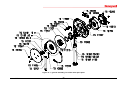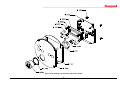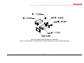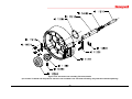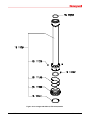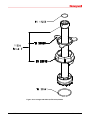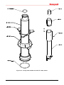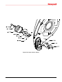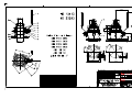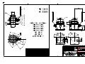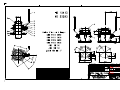
1
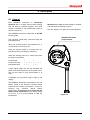
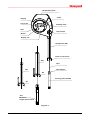
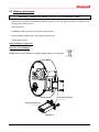
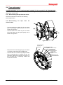
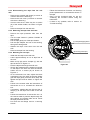
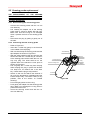
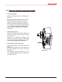
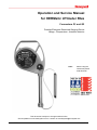
Operation and Service Manual for HERMetic UTImeter Rtex Connectors Q1 and Q2 Portable Electronic Restricted Gauging Device Ullage - Temperature - Interface detector Note : before using the instrument please read this book. This document is subject to changes without notice. Check updates on www.tanksystem.com or contact us at [email protected] 50455/RTEX/1211 1 UTImeter Rtex 1. Table of contents 8.3 8.4 SELECTING THE TEMPERATURE SCALE ........ 27 SELECTING THE TEMPERATURE RESOLUTION 28 8.5 ACTIVATING THE LED ................................ 29 8.5.1 Temporary setting of the LED ............ 29 8.5.2 Permanent setting of the LED ............ 29 8.6 MUTING THE BUZZER .................................. 30 8.7 BACKLIGHT................................................. 30 8.8 CHECKING THE FUNCTIONS BEFORE USING THE INSTRUMENT .................................................... 31 8.8.1 Battery ................................................ 31 8.8.2 Temperature ....................................... 31 8.8.3 Ullage................................................. 31 8.8.4 Interface ............................................. 31 8.9 INSTALLATION OF THE INSTRUMENT ........... 32 8.10 ULLAGE / INTERFACE MEASUREMENT ......... 32 8.11 REFERENCE HEIGHT / INNAGE MEASUREMENT 33 8.12 TEMPERATURE MEASUREMENT ................... 34 1. TABLE OF CONTENTS .................................. 2 2. GENERAL INFORMATION ........................... 4 2.1 2.2 2.3 2.4 2.5 2.6 2.7 SHIPMENT NOTE ............................................ 4 INITIAL INSPECTION ...................................... 4 DOCUMENTATION DISCREPANCIES................ 4 WARRANTY .................................................. 4 CERTIFICATION ............................................. 5 SPARE PARTS ................................................ 5 SERVICE AND REPAIR ................................... 5 3. WORLDWIDE SERVICE STATIONS NETWORK ................................................................ 7 4. RECOMMENDATION FOR SAFE USE ....... 9 5. FUNCTIONS - KEY FEATURES ................. 10 6. DESCRIPTION ............................................... 11 9. CARE AND MAINTENANCE ....................... 35 6.1 GENERAL .................................................... 11 6.2 ULTRA SENSING PROBE ............................. 13 6.2.1 Introduction ....................................... 13 6.2.2 Ullage detection ................................. 13 6.2.3 Interface detection ............................. 14 6.2.4 Temperature measurement ................ 14 6.3 TAPE ........................................................... 15 6.4 TAPE PROTECTION ...................................... 16 6.5 READING INDEX .......................................... 17 6.6 TAPE CLEANER ........................................... 18 6.7 ADDITIONAL LOAD (OPTION) ...................... 19 6.7.1 Viscous liquids (> 800 Cst) ............... 19 6.7.2 Reference height and innage.............. 19 6.8 OTHERS ...................................................... 19 9.1 CARE .......................................................... 35 9.2 CHECKING THE BATTERY ............................ 36 9.2.1 Before starting gauging ..................... 36 9.2.2 During gauging .................................. 37 9.3 BATTERY REPLACEMENT ............................ 38 9.4 TAPE REPLACEMENT ................................... 39 9.4.1 Disconnecting the tape from the sensor 39 9.4.2 Disconnecting the tape from the electronic box ..................................................... 39 9.4.3 Disconnecting the tape from the reel axle 40 9.4.4 Removing the tape from the frame ..... 40 9.4.5 Mounting the new tape ....................... 40 9.5 SENSING PROBE REPLACEMENT ................... 41 9.5.1 Disconnecting the old sensing probe . 41 9.5.2 Connecting the new sensing probe..... 41 9.6 TAPE WIPERS REPLACEMENT AND REMOVING OF TAPE COVER ....................................................... 42 9.7 DISPLAY UNIT REPLACEMENT ..................... 43 9.7.1 Disconnecting the old display unit ..... 43 9.7.2 Connecting the new display unit ........ 43 9.8 VERIFICATION AND CERTIFICATION OF TAPES 43 9.9 VERIFICATION AND ADJUSTMENT OF THE READING INDEX ...................................................... 44 9.10 TEMPERATURE VERIFICATION ..................... 45 9.10.1 Equipment required ........................... 45 9.10.2 Preparing the Ice Point bath .............. 45 9.10.3 Checking the UTImeter ...................... 45 7. EXAMPLES OF INSTALLATION OF THE GAUGING SYSTEM .............................................. 20 7.1 7.2 GENERAL .................................................... 20 EXAMPLE OF INSTALLATION ON A PIPE, CONNECTOR Q2 ...................................................... 21 7.3 EXAMPLE OF INSTALLATION ON THE DECK, CONNECTOR Q2 ...................................................... 22 7.4 EXAMPLE OF INSTALLATION ON A PIPE, CONNECTOR Q1 ...................................................... 23 7.5 EXAMPLE OF INSTALLATION ON THE DECK, CONNECTOR Q1 ...................................................... 24 8. OPERATION ................................................... 25 8.1 BASIC RULES CONCERNING THE 5-KEY CONTROL PAD ......................................................... 25 8.2 SELECTING THE LANGUAGE ........................ 26 50455/RTEX/1211 2 UTImeter Rtex 9.11 ULLAGE/INTERFACE VERIFICATION ............ 46 9.12 ELECTRICAL CHECKING OF THE TAPE ASSEMBLY .............................................................. 47 9.13 VISUAL INSPECTION FOR DAMAGED OR MISSING PARTS ....................................................... 48 9.14 COATED ALUMINIUM PARTS........................ 48 9.15 WINDING ACTION BECOMING STIFF ............. 48 9.16 STORAGE OF HERMETIC DEVICES .............. 48 9.17 TRANSPORTATION OF HERMETIC DEVICES 48 10. TROUBLE SHOOTING ............................. 49 10.1 10.2 10.3 10.4 10.5 SAFETY WARNING ....................................... 49 POWER SUPPLY TROUBLES .......................... 49 TRANSMISSION TROUBLES .......................... 49 ULLAGE AND/OR INTERFACE TROUBLES ..... 50 TEMPERATURE TROUBLES .......................... 50 11. SPECIFICATIONS ..................................... 51 12. SPARE PARTS ............................................ 52 12.1 HOW TO PROCEED ....................................... 52 12.2 LIST OF PARTS DESCRIPTIONS ..................... 52 12.3 SPARE PARTS DRAWINGS ............................ 54 13. VALVES DRAWINGS & DECLARATION OF CONFORMITY ................................................ 63 13.1 VALVES ...................................................... 63 13.2 DECLARATION OF CONFORMITY ................. 63 50455/RTEX/1211 3 UTImeter Rtex 2. General information When returned to Enraf Tanksystem SA or any of its agreed Service Stations equipment must be contamination-free. If it is determined that the Purchasers equipment is contaminated, it will be returned to the Purchaser at the Purchasers expense. Contaminated equipment will not be repaired, replaced, or covered under any warranty until such time that the said equipment is decontaminated by the Purchaser. 2.1 Shipment note The following parts should be included in the shipment: - 1 instrument fitted out with one battery in the display; 1 set of 4 Allen keys: 1.5, 2, 2.5 and 3 mm; 1 Operation and Service Manual. The Purchaser shall notify by fax, telex or in writing of any defect immediately upon discovery, specifying the nature of the defect and/or the extend of the damage caused thereby. 2.2 Initial inspection Check the contents of the shipment for completeness and note whether any damage has occurred during transport. Carry out the “Initial test before installing the instrument” to verify the good functioning. If the contents are incomplete, or if there is a damage, do not use the device. A claim should be filled with the carrier immediately, and Enraf Tanksystem SA Sales or Service organization should be notified in order to facilitate the repair or replacement of the instrument. Where no other conditions have been negotiated between the Vendor and the Purchaser "General Conditions 188" of United Nations shall apply. This instrument has been certified as Intrinsically Safe Instrumentation for only those classes or categories of hazardous areas stated on the instrument label, bearing the mark of the applicable approval authority. No other usage is authorized. 2.3 Documentation discrepancies Unauthorized repair or component replacement by the Purchaser will void this guarantee and may impair the intrinsic safety of the instrument. In particular it is not allowed to repair electronic circuits. The design of the instrument is subject to continuous development and improvement. Consequently, the instrument may incorporate minor changes in detail from the information contained in the manual. In no event shall Enraf Tanksystem SA be liable for indirect, incidental or consequential loss or damage or failure of any kind connected with the use if its products or failure of its products to function or operate properly. 2.4 Warranty Thirty six (36) months after delivery ex works except batteries. Enraf Tanksystem SA do not assume the indemnification for any accident or damage caused by the operation of its product and the warranty is limited to the replacement of parts or complete goods. The Vendor undertakes to remedy any defect resulting from faulty design materials or workmanship. The Vendor's obligation is limited to the repair or replacement of such defective parts by his own plant or one of his authorized service stations. The Purchaser shall bear the cost and risk of transportation of defective parts and repaired parts supplied in replacement of such defective parts. 50455/RTEX/1211 4 UTImeter Rtex 2.5 Certification 2.6 Spare parts When ordering spares identify the spare part by TS number and description. Refer to section “Drawings”. Enraf Tanksystem SA is an ISO 9001 certified company by QMI and MED-D by Det Norske Veritas Certification GmbH. Some spares might be repairable; in this case send the part(s) to any authorised service center or to the factory. In case of urgency, complete replacement units can be made available. Contact the factory or nearest Service Station for details. The equipment has been approved for the electrical intrinsic safety by the following authorities : 2.7 Service and Repair IECEx Zone 0 Ex ia IIB T4 20°C < Ta < +50°C The customer is responsible for any freight and customs clearance charges. If units are sent on a "freight collect" the charges will be invoiced to the customer. Standards used: IEC 600790, Fourth Edition 200401, IEC 6007911, Fifth edition 200607 IEC 6007926, First edition 200403 When returning units or parts for repair to the factory please fill out a service request form (see next page). The serial number (letter "R" followed by 5 digits) is printed on the identification plate as shown on the Figure 6-1. ATEX II 1 G Ex ia IIB T4 / Tamb. 50 °C Standards used: EN60079-0: (2006) EN60079-11: (2007) EN60079-26, (2007) When returned to Enraf Tanksystem SA equipment must be contamination-free. If it is determined that the customers equipment is contaminated, it will be returned to the customer at the customers expense. Contaminated equipment will not be repaired until such time that the customer decontaminates the said equipment. Regarding product compliance against standards updates or new standards, please refer to the Declaration of conformity. Factory Mutual (FM Approvals) CL I, DIV 1, GP C&D, T4 Tamb. 50 °C and CL I, ZN 0, AEx ia IIB T4 Tamb. 50 °C The equipment has been approved as oil/water interface detector according to MARPOL Resolution MEPC.5(XIII) of 13 June 1980 by National Maritime Authorities and/or Classification Societies. If you need a copy of any of these certificates please contact: Enraf Tanksystem SA Rue de l'industrie 2 1630 Bulle, SWITZERLAND Telephone Telefax Web site E-mail : +41-26-91 91 500 : +41-26-91 91 505 : www.tanksystem.com : [email protected] 50455/RTEX/1211 5 UTImeter Rtex Service Request Customer's address: .............................................................................. ................................................................................................................ ................................................................................................................ ................................................................................................................ ................................................................................................................ Telephone: .............................................................................................. E-mail: ..................................................................................................... Fax: ......................................................................................................... Type of unit or part: ................................................................................. ................................................................................................................. Serial number: ......................................................................................... Short description of trouble: ..................................................................... .................................................................................................................. .................................................................................................................. .................................................................................................................. Do you want a quotation before repair is started:..........yes / no............. Repaired unit has to be returned to the following address: .................................................................................................................. .................................................................................................................. .................................................................................................................. .................................................................................................................. .................................................................................................................. 50455/RTEX/1211 6 UTImeter Rtex 3. Worldwide Service Stations network The updated list can be found on our website www.tanksystem.com COUNTRY ADDRESS TELEPHONE/FAX/E-MAIL SWITZERLAND ENRAF TANKSYSTEM SA 2, rue de l'Industrie CH-1630 BULLE Tel : +41-26-91 91 500 Fax : +41-26-91 91 505 [email protected] CANADA PYLON ATLANTIC A Div. Of Pylon Electronics Inc. 31 Trider Crescent., DARTMOUTH, N.S. B3B 1V6 Tel : +1-902-4683344 Fax : +1-902-4681203 [email protected] CHINA HUA HAI EQUIPMENT & ENGINEERING Tel : +86-21-68183183 CO LTD Fax : +86-21-68183115 Factory 7, Lane 1365, East Kang Qiao Road [email protected] Kang Qiao Industrial Zone, Pu Dong SHANGHAI, P.C. 201315 GERMANY CHRISTIAN BINDEMANN MARINE CONSULTING Antonie-Möbis-Weg 4 HAMBURG 2523 Tel : +49-40-41918846 Fax : +49-40-41918847 [email protected] GREECE SPANMARIN 86, Filonos Street GR-185 36 PIRAEUS Tel : +30-210-4294498 Fax : +30-210-4294495 [email protected] JAPAN DAIWA HANBAI CORPORATION LTD 2-10-31, Mitejima, Nishiyodogawa-ku OSAKA 555-0012 Tel : +81-6-64714701 Fax : +81-6-64729008 [email protected] KOREA World Ocean CO., LTD Rm1001, Hae-deok Bldg., 1212-11 Choryang-dong Dong-Gu BUSAN Tel : +82-51-462-2554/5 Fax : +82-51-462-0468 [email protected] MEXICO URBAN DEL GOLFO S.A. DE C.V. Ave. Ejército Mexicano 1902 Col. Loma del Gallo 89460 CD. MADERO, TAMPS. MEXICO Tel : +52-833-2170190 Fax : +52-833-2170190 [email protected] NETHERLANDS B.V. TECHNISCH BUREAU UITTENBOGAART Brugwachter 13 NL-3034 KD ROTTERDAM 50455/RTEX/1211 Tel : +31-10-4114614 Fax : +31-10-4141004 [email protected] 7 UTImeter Rtex The updated list can be found on our website www.tanksystem.com COUNTRY ADDRESS TELEPHONE/FAX/E-MAIL PORTUGAL CONTROLIS Soc. Com. Equipamentos de Controlo, Lda. Rua Conceiçao Sameiro Antunes, 26E 2800-379 COVA DA PIEDADE Tel : +351-21-2740606 Fax : +351-21-2740897 [email protected] RUSSIA NPP "GERDA" Vilisa Latsisa str. 17 Building 1 125480 MOSCOW Tel : +7-495-7558845 Fax : +7-495-7558846 [email protected] SINGAPORE HUBBELL INT'L (1976) PTE LTD 322 Thomson Road SINGAPORE 307665 Tel : +65-6-2557281 Tel : +65-6-2550464 Fax : +65-6-2532098 [email protected] SPAIN E.N.I. Electronica y Neumatica Industrial, S.A. C/Jon Arrospide, 20 (Int.) 48014 BILBAO Tel : +34-94-4746263 Fax : +34-94-4745868 [email protected] SWEDEN INSTRUMENTKONTROLL Lars Petersson AB Varholmsgatan 1 414 74 GÖTEBORG Tel : +46-31-240510 Tel : +46-31-240525 Fax : +46-31-243710 [email protected] TURKEY YEDI DENIZ Setustu, Izzetpasa Yok.1 TR 34427 Kabatas ISTANBUL Tel : +90.212.251 64 10 / 3 lines Fax : +90.212.251 05 75 [email protected] [email protected] UNITED ARAB EMIRATES MARITRONICS TRADING L.L.C. P.O. Box 6488 Shed # 72, Jadaf Ship Docking Yard DUBAI Tel : +971-4-3247500 Fax :+971-4-3242500 [email protected] UNITED KINGDOM ENERGY MARINE (INTERNATIONAL) LTD. Tel : +44-1525-851234 12 Clipstone Brook Industrial Estate Fax :+44-1525-852345 Cherrycourt Way [email protected] LEIGHTON BUZZARD, BEDS LU7 4TX U.S.A / TEXAS HONEYWELL HERMETIC 4522 Center Street DEER PARK, TX 77536 50455/RTEX/1211 Tel : +1-281-930 1777 Fax : +1-281-930 1222 Toll free call in the USA: 1-800-900 1778 [email protected] 8 UTImeter Rtex 4. Recommendation for safe use 1. This Operation and Service Manual is a guide in order to help the user to operate the instrument safely and correctly. 2. Nevertheless the maker disclaims all responsibility and liability for damage resulting from the use of the equipment regardless of the cause of the damage. 3. Attention is drawn to the possible hazard due to electrostatic charges which may be present in the tank. This may happen in particular with static accumulator liquids, i.e. liquids which have low conductivity of 50 picoSiemens/metre (pS/m) or less. 4. It is very important that the instrument is grounded to the tank before the probe is introduced into the tank and remains grounded until after complete withdrawal from the tank. 4.1. If the instrument is installed with the quick connect coupler, grounding is effected through the quick connect coupler and the mating nipple of the valve provided that these parts are kept clean and free from corrosion in order to guarantee electrical conductivity. If a grease is used for this purpose, it must be one which contains graphite. 4.2. If the instrument is not connected to the mating deck valve, the instrument has to be also earthed by means of the grounding cable and clamp. 5. It is anticipated that the user will have specific operating methods laid down to ensure safety when using this type of apparatus. In this case the user's instructions shall be strictly observed. 6. In the absence of such instructions the following should be noted: 6.1. If a metal sounding pipe is fitted beneath the deck valve or tank is inerted, then ullaging, etc. is permissible at any time with no restriction. 6.2. If there is no sounding tube or tank is not inerted, the following precautions shall be taken: 6.2.1. If the cargo is not a static accumulator liquid, i.e. its conductivity is more than 50 pS/m, then ullaging is permitted provided that the instrument is properly grounded and earthed before the probe is inserted into the tank and remains earthed until the probe has been removed from the tank. 6.2.2. If the cargo is a static accumulator liquid, i.e. its conductivity is less than 50 pS/m, then ullaging is permitted provided that: 6.2.2.1. 6.2.2.2. The instrument is properly grounded and earthed before the probe is inserted into the tank and remains earthed until the probe has been removed from the tank. The apparatus is not introduced into a tank until at least 30 minutes have elapsed after completion of any loading operation or stopping the injection of inert gas. 6.3. For further guidance refer to International Safety Guide for Oil Tankers and Terminals (ISGOTT), ISBN 10 85609 291 7, Fifth Edition 2006, or consult the appropriate Legislative Authority for the installation. 7. Warning: Substitution of components may impair the intrinsic safety. Change of battery must be carried out in safe area only (non flammable atmosphere); Use only an approved battery. To prevent ignition hazard, avoid impact or friction of the device aluminum box. 8. This product and his use is / may be related to international, national, local or company regulations or standards. It is the customer / user responsibility to ensure that the way to use the device complies with such applicable regulations or standards. 9. This device is a portable product. It must not be permanently installed on the tank and must be disconnected after use and stored in a safe and dry area. 50455/RTEX/1211 9 UTImeter Rtex 5. Functions - Key Features This HERMetic instrument is a portable multiple functions gauging system that is designed to perform under restricted conditions in a single operation 3 measurements: a) Ullage (outage). Optionally innage is available¹. b) Oil/water Interface level. Tape resolution: 1 mm (1/16 ") Tape accuracy: ±1.5 mm for 30 m (±1/16 " approx. for 100 feet) Ullage/interface detection accuracy: ±2 mm (±0.08 " approx.) Minimum detectable tank bottom interface or liquid level: 4 mm (0.16" approx.). Zero reference level c) Temperature by continuous reading at any level. Ambient temperature range: -20°C to 50°C ( -4°F to 122°F) Sensor measurement range:-40°C to 90°C ( -40°F to 194°F) Tape protection Resolution: 0.01° or 0.1°, selectable Tank top Accuracy over calibration range: ±0.1°C (0°C to 70°C); ±0.2°F (32°F to 158 °F) Vapour Temperature reading: °C or °F, selectable. Ullage level This HERMetic device meets the requirements of API MPMS Chapter 7 2001, table 3, ISO 4268 and IP PMM Part IV. Product Thanks to the small diameter of the sensing probe this instrument can be used with valves of diameters down to 25 mm (1”) only. A tape protection tube prevents closing the valve on the tape through inadvertence. Interface level ¹ An additional device, usable with 2” valves only, can be provided that allows Reference Height and Innage measurement. Available on “Visc” models. 50455/RTEX/1211 Water 10 UTImeter Rtex 6. Description 6.1 General Each HERMetic instrument is individually identified with a 6 digits serial number starting with the letter R, example R10058. This serial number is printed on the identification plate as shown on Figure 6-1. Maintenance is easy because design is modular and allows quick exchange of parts. See also Figure 6-2 to get to know the equipment. The HERMetic instrument is fitted with an ULTRA sensing probe. identification plate serial number The unit emits control beep, continuous beep and intermittent beep. When the sensing probe is surrounded by air, a control beep occurs every 2 sec. When the sensing probe is in contact with any petroleum product, the beep is continuous. When the sensing probe is in contact with water the beep is intermittent. Control beep Continuous beep Intermittent beep • • • • • • • • • • • • • • • • • • A light signal (LED) can also be activated that blinks at the same frequency as the buzzer tones. This can be useful in noisy environments or at night. A backlight can be used at night to light up the display. The HERMetic instrument is powered by a 9 Volt battery stored in the electronic terminal named instrument unit. Current consumption is very low, ensuring long operation without battery replacement. A continuous tone means that the battery needs replacement. If the battery power is too low, it is no more possible to read the temperature. 50455/RTEX/1211 Figure 6-1 11 UTImeter Rtex Identification plate Crank Display 5 keys pad Reading index LED Tape cleaner Buzzer Display unit Storage tube SS1 Quick connector Q1 SS2 Tape Tape adaptor SS1 Q2 Sensing probe ULTRA Q2 Visc device for innage measurement Figure 6-2 50455/RTEX/1211 12 UTImeter Rtex 6.2 ULTRA sensing probe 6.2.1 Introduction The ULTRA sensing probe consists of a stainless steel tube terminated by a hightech plastic head which cannot be removed from the tube. The sensing probe includes an ultrasonic liquid level sensor, a temperature sensor and a conductivity electrode. The sensitivity for ullage and interface measurement is not adjustable. The temperature measurement is calibrated at the factory and does not require subsequent adjustment. 6.2.2 Ullage detection Reaction point Air Liquid 2 0 1 1 2 1 3 1 4 0 5 6 1 The ullage detector consists of two piezoceramic plates and electronic circuits. When the sensor head is immersed in a non-conductive liquid (oil or petroleum), the emitted ultrasonic signal is detected by the receiver, coded and sent to the instrument unit which activates the buzzer with the continuous beep. 4 mm Ultrasonic level sensor Figure 6-3 The reaction point is located 4 mm (5/32") from the sensor bottom and identical with the zero-point of the tape graduation. 50455/RTEX/1211 13 UTImeter Rtex 6.2.3 Interface detection The principle consists of a conductivity measurement between an active electrode and a grounded electrode. When the liquid is conductive (as water), the ullage sensor detects the presence of 6 1 the liquid as well and the conductivity electrodes and associated electronic circuits modulate the coded signal to generate the intermittent beep. Air Oil Interface level 2 1 0 1 1 2 3 1 4 0 5 Oil 4 mm Water Interface sensor Figure 6-4 The reaction point is located 4 mm (5/32") from the sensor bottom and identical with the zero-point of the tape graduation. 6.2.4 Temperature measurement The sensing element is a Platinum Resistance Temperature Detector (RTD) element. The element is located in the temperature electrode, which is filled in with a heat transfer compound paste to reduce the response time. The RTD element signal is digitized, and then all errors (offset, non-linearity and drift) are corrected and compensated by the micro-controller located in the sensor probe. The RTD element characteristics are stored in the sensor memory 6 1 and are dedicated to one sensor. For this reason, changing a sensor does not require a new calibration. All data are serialised and sent by the microcontroller to the Display Unit. Temperature settings (resolution, scale) are easy to select by pressing the 5-key control panel. Temperature level 1 0 1 1 2 3 1 4 0 Liquid 2 5 Air 4 mm Temperature sensor Figure 6-5 The reaction point is located 4 mm (5/32") from the sensor bottom and identical with the zero-point of the tape graduation. 50455/RTEX/1211 14 UTImeter Rtex 6.3 Tape The ETFE (TEFZEL) coated tape provides 3 main functions : index is set up at the zero ullage level, the reading of the tape is identical to the ullage. It holds the sensing probe. It contains 2 wires for transmitting the signal and the power between the display unit and the probe. The steel tape itself is used as a grounding wire between the sensing probe tube and the display unit. It is graduated and therefore makes it possible to determine the distance between the reaction point and the reading index. If the reading STEEL TAPE TEFZEL WIRE Figure 6-6 The standard graduation is a double side type that shows the metric graduation on one side and the inch one on the other side. The tape is mounted on the equipment according to the need. 3 4 23 23 5 9 23 inch side 7 10 11 12 13 14 7 15 metric side Figure 6-7 50455/RTEX/1211 15 UTImeter Rtex 6.4 Tape protection The tape protection tube is a mechanical safety device which prevents the valve from being closed as long as the sensing probe is inside the tank. When the sensing probe is lowered the protection tube will follow the sensing probe by gravity until the tube is retained by a ring located inside the coupler. In that position the protection tube prevents closing the valve. When the tape is wound up the protection tube will stay in position until it is pushed up by the sensing probe. Before instrument is used check that the protection tube is moving freely. For cleaning purposes the protection tube is slotted. TAPE PROTECTION TUBE STORAGE TUBE SENSOR RETAINER QUICK CONNECT COUPLER BALL VALVE VALVE OPEN VALVE CLOSED Figure 6-8 50455/RTEX/1211 16 UTImeter Rtex 6.5 Reading index 1300 Zero ullage 1200 Reference level of tank 1100 1000 900 800 700 600 500 400 300 200 100 Liquid level 0 Reaction point Figure 6-9 The tape reading at the height of the reading index of the instrument is indicating the distance between the reaction point and the reading index. If the instrument is installed in such a way that the reading index is at the same level as the zeroullage reference level the reading of the tape corresponds to the ullage providing the reaction point of the sensing probe is positioned at the liquid level. 50455/RTEX/1211 If the reading index is positioned below or above the reference level a positive or negative correction of the tape reading is necessary. See also chapter 7 “Examples of installation of the gauging system”. 17 UTImeter Rtex 6.6 Tape cleaner position "DOWN": the wipers are not working, the tape is free; - position "UP": the wipers are cleaning the tape. Refer to Figure 6-10. - This HERMetic equipment is fitted with a tape cleaner that helps draining the liquid back to the tank when rewinding the tape. It is very easy to operate: Tape cleaner DOWN = wipers not engaged Tape cleaner UP = wipers engaged Figure 6-10 50455/RTEX/1211 18 UTImeter Rtex 6.7 Additional Load (option) 6.8 Others An additional load (see Figure 6-2) on the sensing probe can be provided for one of the following reasons. This option is available on UTImeter Rtex Visc equipped with the storage tube Q2 (2”) and needs valves of at least 2” size. The tape is coiled on a reel which holds also the electronic box and the display unit. The reel is assembled to the electronic box and can be locked at discrete positions by means of a stopping mechanism in the crank. Pull the crank to free the stopping mechanism. 6.7.1 Viscous liquids (> 800 Cst) For gauging viscous liquids the load can help the sensing probe in penetrating the liquid and in keeping the tape straight. The external reel flange and the frame are made in aluminium coated with polyamid PA 11 (RILSAN). 6.7.2 Reference height and innage For measuring the reference height of a tank and innages the load allows the sensing probe to touch the dip/datum plate. 50455/RTEX/1211 The storage tube is threaded to the frame. The storage tube is equipped with a quickconnector which fits on the HERMetic valves. 19 UTImeter Rtex 7. Examples of installation of the gauging system 7.1 General The gauging system consists of the HERMetic instrument and the associated HERMetic valve. Two types of connector can be provided as shown on Figure 7-1. When designing the gauging port and to avoid damaging the tape during rewinding it is advised to chamfer or to grind all sharp edges (on pipes, flanges, etc.) that could damage the tape when operating the gauge. Figure 7-1 The following sections, respectively 7.2, 7.3 for connector Q2 and 7.4, 7.5 for connector Q1, describe 2 examples for installing the valves and adjusting the height of the gauging system. The valves should be installed in such a way that the zero-ullage level coincides with the reading index level, so that no correction would be necessary. For achieving this it may be necessary to install an adjusting pipe between the deck and the valve. If the valves are installed directly on deck or if for any reason the level of the reading index is below or above the zero-ullage level, then a correction table should be used. There should be no internal tank structure between the valve outlet and the tank bottom such that will impede the path of the equipment into the tank. All valves shall be installed at the same level. Small systematic level error can be corrected by adjusting the reading index accordingly. 50455/RTEX/1211 20 UTImeter Rtex 7.2 Example of installation on a pipe, connector Q2 SS1 Q1 Tank Zero Ullage level SS1 Q1 Reading index Reading index 460mm 460mm HC HV HV H Thread TS supply Customer supply Flange HT HT Tank Deck Figure 7-2 Valve designation C.2-SS; C.2-SS-W; C.2-SS-BL; C.2-SS-SEC Bottom connection thread or flange Boring 2” *) HV (mm) 141 *) HT (mm) H-615 *) Dimension HV is without gasket. If gaskets are used dimension HT is reduced by thickness of gasket. 50455/RTEX/1211 21 UTImeter Rtex 7.3 Example of installation on the deck, connector Q2 Tank Zero Ullage level HX HX SS1 Q2 SS2 Q2 H Reading index Tank Deck Reading index 474mm 474mm HV HV Flange Flange Figure 7-3 Valve designation C.2-SS; C.2-SS-W; C.2-SS-BL; C.2-SS-SEC Bottom connection thread or flange Boring 2” *) HV (mm) 141 *) HX (mm) H-615 *) Dimension HV is without gasket. If gaskets are used dimension HX is reduced by thickness of gasket. 50455/RTEX/1211 22 UTImeter Rtex 7.4 Example of installation on a pipe, connector Q1 SS1 Q1 Tank Zero Ullage level SS1 Q1 Reading index Reading index 460mm 460mm HC HV HV H Thread TS supply Customer supply Flange HT HT Tank Deck Figure 7-4 Valve designation A.1-SS C.1-SS C.1-SS C.1-SS C.2-SS C.2-SS-W C.2-SS C.2-SS-W A.2-SS A.2,5-SS A.4-SS 1" 1" 1" 1" 2" 2" 2" 2,5” 4” Bottom connection thread thread flange JIS 5K25 flange JIS 5K50 thread flange flange flange flange *) HV (mm) 120 65 79 79 141 141 172 99 140 HC (mm) na na na na 14 14 41 53 58 H-580 H-525 H-539 H-539 H-615 H-615 H-673 H-612 H-658 Boring *) HT (mm) *) Dimension HV is without gasket. If gaskets are used dimension HT is reduced by thickness of gasket. 50455/RTEX/1211 23 UTImeter Rtex 7.5 Example of installation on the deck, connector Q1 Tank Zero Ullage level HX HX SS1 Q1 H SS1 Q1 Reading index Reading index 460 mm 460 mm Tank Deck HC HV HV Thread Flange Figure 7-5 Valve designation A.1-SS C.1-SS C.1-SS C.1-SS C.2-SS C.2-SS-W C.2-SS C.2-SS-W A.2-SS A.2,5-SS A.4-SS 1" 1" 1" 1" 2" 2" 2" 2,5” 4” Bottom connection thread thread flange JIS 5K25 flange JIS 5K50 thread flange flange flange flange *) HV (mm) 120 65 79 79 141 141 172 99 140 HC (mm) na na na na 14 14 41 53 58 H-580 H-525 H-539 H-539 H-615 H-615 H-673 H-612 H-658 Boring *) HX (mm) *) Dimension HV is without gasket. If gaskets are used dimension HX is reduced by thickness of gasket. 50455/RTEX/1211 24 UTImeter Rtex 8. Operation 8.1 Basic rules concerning the 5-key control pad Apart from the "ON" / "OFF" keys that are selfexplanatory, there are 3 other keys that help in customising the unit: - pressing "+" allows to scroll down the menus, a pointer show the actual menu you have selected, - pressing "-" allows to exit a menu, pressing "enter" (later on named "E") allows to enter a specific menu. The small pointer displayed on the left is showing the active setting. - Figure 8-1 50455/RTEX/1211 25 UTImeter Rtex 8.2 Selecting the language English, German or French languages can be selected by following the sequences described in Figure 8-2. UTImeter ON Ver x.xx Battery ééééé 97% Init. LED menu + ********* 25.94°C + T. unit + - + E Settings Resol. + - Language E - English + - Deutsch + - Francais + Figure 8-2 - Switch on the equipment, Wait until the temperature is displayed, Press on "+" to enter the settings menu, Press on "enter", "LED menu" is displayed, Press on "+"; "T. unit" is displayed, Press on "+", "Resol." is displayed, Press on "+", "Language." is displayed, Press on "enter", Select the language by pressing on "+" one or more times, the display shows the language selected, Press "-" two times to come back in measurement mode. The new setting is stored in the permanent memory. 50455/RTEX/1211 26 UTImeter Rtex 8.3 Selecting the temperature scale The temperature can be displayed either in Celsius or Farenheit degrees. Refer to Figure 8-3. UTImeter ON Ver x.xx Battery ééééé 97% Init. LED menu + ********* 25.94°C + E T. unit - > °C - °F + + - + °C > °F E Settings Figure 8-3 - Switch on the equipment, Wait until the temperature is displayed, Press on "+" to enter the settings menu, Press on "enter", "LED menu" is displayed, Press on "+"; "T. unit" is displayed, Press on "enter", Select the scale by pressing on "+" one or more times, the pointer shows the scale selected, Press "-" two times to come back in measurement mode. The new setting is stored in the permanent memory. 50455/RTEX/1211 27 UTImeter Rtex 8.4 Selecting the temperature resolution The temperature reading can be given with 1 or 2 digits after the dot. Select the appropriate resolution as shown on Figure 8-4. UTImeter ON Ver x.xx Battery ééééé 97% Init. LED menu + ********* 25.94°C + T. unit + - + E Settings - E Resol. >0.0° + - + > 0.00° Figure 8-4 - Switch on the equipment, Wait until the temperature is displayed, Press on "+" to enter the settings menu, Press on "enter", "LED menu" is displayed, Press on "+"; "T. unit" is displayed, Press on "+", "Resol." is displayed, Press on "enter", Select the resolution by pressing on "+" one or more times, the pointer shows the resolution selected, Press "-" two times to come back in measurement mode. The new setting is stored in the permanent memory. 50455/RTEX/1211 28 UTImeter Rtex 8.5 Activating the LED Refer to Figure 8-5. The LED can be activated on 2 modes: - one is temporary, it is automatically erased when the unit is switched off, in order to save the battery life; - the other is permanent, it will stay even is the unit is switched off. UTImeter ON Ver x.xx Battery E ééééé 97% Init. - LED menu E LED - + + ********* + + 25.94°C LED yes - LED set. - LED no - enable E + + + - - + disable E Settings Figure 8-5 8.5.1 Temporary setting of the LED - Switch on the equipment, - Wait until the temperature is displayed, - Press on "+" to enter the settings menu, - Press on "enter"; "LED menu" is displayed, - Press on "enter"; "LED" is displayed, - Press on "enter", then select by pressing "+" the mode: "LED yes" or "LED no". - Press "-" two times to come back in measurement mode. It is always possible to change the status of the LED during gauging, by using the same menu again. If not done before, switching off the unit will automatically light off the LED. 8.5.2 Permanent setting of the LED - Switch on the equipment, - Wait until the temperature is displayed, - Press on "+" to enter the settings menu, - Press on "enter"; "LED menu" is displayed, - Press on "enter"; "LED " is displayed, - Press on "+", "LED Set." is displayed, - Press on "enter", - "Enable" or "disable" the LED by pressing on "+" one or more times, - Press "-" two times to come back in measurement mode. The new setting is stored in the permanent memory. Remember that the LED needs an extra power and reduces the battery life accordingly. 50455/RTEX/1211 29 UTImeter Rtex 8.6 Muting the buzzer UTImeter ON Ver x.xx Battery ééééé 97% Init. Buzzer OFF ********* - / medium / 5 min E Backlight ON 25.94°C auto Figure 8-6 When in measurement mode it is possible to mute the buzzer. - Press on "-", - Press on "-" again to reset the buzzer. IMPORTANT NOTE: in order to prevent any misuse of the equipment, there is an automatic reactivation of the buzzer each time the medium changes (air to liquid, liquid to water, etc.) or after 5 minutes muting. To keep the buzzer muting, press again on "-". 8.7 Backlight Refer to Figure 8-6. When in measurement mode press "enter": this switches on the backlight. After around 10 seconds, the light switches off automatically to save the battery life. 50455/RTEX/1211 30 UTImeter Rtex 8.8 Checking the functions before using the instrument Before installing the HERMetic instrument as described in section 8.9, the following tests are recommended to ensure that the instrument is ready to work. 8.8.1 Battery 8.8.3 Ullage Refer to section 9.2 "Checking the battery". Switch on the unit. The buzzer shall beep every 2 sec. Check the ullage in a glass of water. Check the ullage by immersing the ultrasonic gap sensor but not the electrodes (position A); The buzzer shall beep continuously. 8.8.2 Temperature Switch on the unit. The buzzer shall beep every 2 sec. When the temperature is displayed, check that it shows the surrounding temperature. 8.8.4 Interface Switch on the unit. The buzzer shall beep every 2 sec. Check the interface in a glass of water. Check the interface by immersing the interface electrodes also (position B). The buzzer shall beep intermittently. position B position A Figure 8-7 50455/RTEX/1211 31 UTImeter Rtex As soon as the sensor comes in contact with the petroleum product the control beep will change for a continuous beep. Raise the sensing probe again until the continuous beep stops and lower the sensing probe again slowly until the continuous beep is heard again. Now the ullage level can be read against the ullage reference. If the zero-ullage reference does not correspond to the reading index of the instrument, a correction has to be made accordingly. 8.9 Installation of the instrument This HERMetic equipment must be coupled to a certified HERMetic valve. Before starting please read carefully the chapter “Recommendation for safe use” and follow your company's safety instructions. Check that the HERMetic valve is closed. Lower the sensing probe further until the sensor touches the oil-water interface. As soon as the sensor comes in contact with water the continuous beep will change for an intermittent beep. The difference between the ullage reading and the interface reading represents the thickness of the product layer. Remove the end cap (weather cap / blind cover / security cover) of the HERMetic valve. Clean the seal surfaces of the nipple of the valve and of the coupler of the instrument from dust or grease. Note: Cleaning of the mating surfaces is very important for earth grounding purpose and for good accuracy on zero reference level. When the measurements are completed, switch off the unit, turn the tape cleaner on "UP" position and wind up the tape until the sensing probe is in the storage tube. The reading on the tape shall be less than 420 mm or 1 ft 5 inch. Check whether the tape protection tube is moving freely. Close the valve and disconnect the instrument from the nipple. Install the HERMetic instrument on top of the valve by means of the quick coupler. Ensure that the equipment is properly earthed. If not, ground it with the (optional) grounding cable before operating. Put the end cap back on the valve. IMPORTANT NOTE 8.10 Ullage / interface measurement Do not use any tool to activate the crank handle. In case of abnormal effort required, identify its cause and solve the problem. See section 9.15. Install the HERMetic equipment as per 8.9 "Installation of the instrument”. Do not activate the crank handle too fast, specifically during the rewinding operation. This may generate a rocking of the sensor and some damage (sensor / tape) in case of chocs onto the tank structure. Open the valve by turning the handle. Switch on the equipment: a control beep is audible every 2 seconds. When activating the crank handle, always control through the window that the tape is really moving. If the tape does not move when the handle is activated, stop winding and identify its cause. Make sure the tape cleaner is in “DOWN” position. If the tape is still not moving despite correct position of the tape cleaner, please check if the sensor is stuck somewhere. Put the tape cleaner on the "DOWN" position. Disengage the knob of the crank handle and lower the sensing probe into the tank by turning the reel. Make sure that the tape does not rub on any sharp edge when lowering as its insulation could be damaged. 50455/RTEX/1211 32 UTImeter Rtex tape cleaner on the "DOWN" position during the final checking. Calculate the free water height by subtracting the index reading to the reference height. 8.11 Reference height / innage measurement If the unit is fitted with the additional load (model SS2 Q2, see Figure 8-8) then reference height / innage measurement are possible. Reengage the tape cleaner on the "UP" position and raise up the sensing probe until checking the ullage (see details in section 8.10 “Ullage / interface measurement”). Release the tape cleaner for final checking of the ullage. Calculate the innage by subtracting the index reading and the free water height to the reference height determined before. When the measurements are completed, switch off the unit, engage the tape cleaner on the "UP" position and wind up the tape until the sensing probe is in the storage tube. The reading on the tape shall be less than 420 mm or 1 ft 5 inch. Figure 8-8 Close the valve and disconnect the instrument from the nipple. Install the HERMetic equipment as per 8.9 "Installation of the instrument”. Put the end cap back on the valve. Open the valve by turning the handle. Put the tape cleaner on the "DOWN" position. Disengage the knob of the crank handle and lower the sensing probe into the tank by turning the reel. Make sure that the tape does not rub on any sharp edge when lowering as its insulation could be damaged. Tape reading + 4 mm (5/32") Distance from dip/datum plate to reading index = 1200 1100 1000 900 When the sensing probe comes in contact with the dip/datum plate record the distance shown on the reading index. See Figure 8-9. The exact distance from the plate to the reading index is (reading + 4 mm / + 5/32”) which is the reference height providing the reading index level has been adjusted to the zero ullage level of the tank. If the tank zero ullage is levelled above or below the reading index, an additional correction shall apply. For more details refer to section “Installation of the gauging system”. 800 700 600 500 400 300 200 sensor with load Turn the tape cleaner on "UP" position. Switch on the unit and raise up the sensing probe until checking the oil/water interface if any (see details in section 8.10 ”Ullage / interface measurement”). To get a better accuracy of the interface level, release the 50455/RTEX/1211 100 0 Dip/Datum plate + 4 mm (5/32") Figure 8-9 33 UTImeter Rtex 8.12 Temperature measurement Install the HERMetic equipment as per 8.9 "Installation of the instrument”. Open the valve by turning the handle. IMPORTANT NOTE Switch on the unit: a control beep is audible every 2 seconds. As mentionned in 8.6 "Muting the buzzer" it is easy to mute the buzzer during the temperature measurement by pressing on "-". Put the tape cleaner on the "DOWN" position. Disengage the knob of the crank handle and lower the sensing probe to the deepest reading desired. Make sure that the tape does not rub on any sharp edge when lowering; its insulation might be damaged. Recall that after 5 minutes have elapsed or each time the probe detects a change of the medium (air, liquid, water), the buzzer will reactivate automatically. To keep it muting, press on "-" again. The position of temperature sensor coincides with zero of tape, so the tape index reading shows directly level at which temperature is measured When the desired temperature ullage level is reached, joggle the sensing probe approximately 300 mm (1 foot) above and below the desired measurement level until the displayed temperature reading settles. For heavy crude oils which have a low thermal conductivity and a viscous nature, the joggling procedure is a necessity to assure an accurate temperature reading in a minimum amount of time. When temperature has settled, record it. Engage the tape cleaner on "UP" position. Raise the probe to the next ullage level to be measured and repeat the procedure a.m. To joggle the sensing probe the tape cleaner must be on the "DOWN" position. When the measurements are completed, switch off the unit, engage the tape cleaner on "UP" position and wind up the tape until the sensing probe is in the storage tube. The reading on the tape shall be less than 420 mm or 1 ft 5 inch. Close the valve and disconnect the instrument from the nipple. Put the end cap back on the valve. 50455/RTEX/1211 34 UTImeter Rtex 9. Care and Maintenance 9.1 Care Clean the instrument of any excess of liquid after use. Make sure that the sensing probe is completely stored in the storage tube after use (reading index shall indicate less than 420 mm or 1 ft 5 "). Check the tightness of the reading index screws and if necessary adjust the level, refer to section 9.9. Store the instrument in a safe, dry and dust free location with an ambient temperature between +5°C to +45°C, refer to section 9.16. Check periodically (at least every 6 months) the continuity of grounding by measuring the electrical resistance between the tape adaptor (or the sensing probe tube) and the quick connect coupler. Resistance should not exceed 10 . Periodically clean carefully the sensor probe, the frame and the mechanical parts, as storage tube, tape, with an appropriate solvent. Note: always reassemble the storage tube to the frame in the vertical position to allow the O-ring to seat properly in the tube. Check periodically the condition of the tape cleaner. With such conductive liquids which form salts when drying, wash the sensing probe with water or alcohol and brush it very gently with a soft brush to prevent a water detection error due to a short-circuit between the electrode and the tube. 50455/RTEX/1211 35 UTImeter Rtex 9.2 Checking the battery Please note that in case you have to change the battery, it must be done only in a safe area. Refer to section 9.3 "Battery replacement". 9.2.1 Before starting gauging Switch on the unit. The buzzer tones every 2 seconds if the battery is not too low. The following sequences are displayed as per Figure 9-1, the 4th sequence shows the remaining power of the battery in percentage and as a bar-graph. If the power left is less than 50% we recommend to have a spare battery ready for exchange. See also 9.3 "Battery replacement". If the power left is less than 20% the message is blinking to advise that the power may not be enough to carry out all the work. UTImeter ON Ver x.xx Battery ééééé 97% Init. ********* 25.94°C Figure 9-1 If the battery is too low, the unit will stop on the message "battery" as shown on Figure 9-2 and the buzzer tones continuously. Change the battery as per 9.3 "Battery replacement". UTImeter ON Ver x.xx Battery 0% ░ Init. ********* Battery Figure 9-2 If it is not possible to switch on the unit, the battery is out or work. Change the battery first, as per 9.3 "Battery replacement". 50455/RTEX/1211 36 UTImeter Rtex 9.2.2 During gauging When the unit is already switched on and working, it is always possible to see what power is left with the battery by entering the settings menu: - Press on "+" to enter the settings menu, Press on "enter", "LED menu" is displayed, Press on "+"; "T. unit" is displayed, Press on "+", "Resol." is displayed, Press on "+", "Language" is displayed, Press on "+", "Battery" is displayed, Press on "enter", The remaining battery power is displayed in percentage and as a bar-graph; pressing "+" again allows to see the tension of the battery (B); the last information (A) is internal. Press "-" two times to come back in measurement mode. ON UTImeter Ver x.xx Battery 47% éé LED menu Init. + ********* 25.94°C + T. unit + - + E Settings Resol. + Language + - E Battery - éé 47% + + B 7.62 V + A 3.22 V Figure 9-3 50455/RTEX/1211 37 UTImeter Rtex 9.3 Battery replacement Warning : change the battery only in a non hazardous area. Unscrew the 2 screws of the battery holder using the 2,5 mm Hex Allen key which is located on the carrying case. See Figure 9-4. Pull it gently out. Change the battery (one-way only device). See Figure 9-4. Push the battery holder back in its housing (one-way only). Tighten the 2 screws. Only one battery is approved: Duracell / Procell MN1604 Caution: Do not throw batteries in rubbish; deposit them in a recycling bin. one-way only device one-way only device Figure 9-4 50455/RTEX/1211 38 UTImeter Rtex 9.4 Tape replacement THE REPLACEMENT OF THE TAPE DOES NOT REQUIRE TO RE-CALIBRATE THE TEMPERATURE. Follow the different sequences as described below. The Figure 12-1 : general assembly, list of the main spare parts can also help. 9.4.1 Disconnecting the tape from the sensor Follow the instructions of section 9.5 "Sensing probe replacement". 9.4.2 Disconnecting electronic box the tape from the Unscrew with the 2.5 Allen key the 2 screws (A) of the battery holder and pull it out as shown on Figure 9-5. Unscrew with the 2.5 Allen key the 4 screws (B) of the display unit and pull it gently out as shown on Figure 9-5. (B) (A) Figure 9-5 (C) connecting plug to display unit (D) grounding cable of tape (E) black oversleeve of tape (F) securing screw Disconnect the connecting plug (C) as shown on Figure 9-6 and remove the display unit. Unscrew with the 2.5 Allen key the tape holder (G) by removing the 2 screws (F) and the grounding cable (D) as shown on Figure 9-6. Do not loose the 2 remaining screws that secure the reel axle. (G) tape holder (H) tape (I) securing screw Figure 9-6 50455/RTEX/1211 39 UTImeter Rtex Follow the instructions of section 9.5 "Sensing probe replacement" to re-install the sensor on the tape. Carry out the functional tests as per 8.8 "Checking the functions before using the instrument". If there is any problem, refer to section 10 "Trouble shooting". 9.4.3 Disconnecting the tape from the reel axle Remove the external reel flange (3 screws to unscrew with the 2.5 Allen key). Remove the axle cover (3 screws to unscrew with the 2.5 Allen key). Unscrew with the 2.5 Allen key the 4 screws (K) of the washer holder, as shown on Figure 9-7. Remove the tape from the reel axle. 9.4.4 Removing the tape from the frame Remove the tape protection tube from the tape. Turn the tape cleaner in position "DOWN" to free the tape. Pull the tape gently out of the tape cleaner. Pull the tape adaptor end out of the housing, through the storage tube. Slacken the tape a few turns from the reel axle. Remove the tape from the housing. (L) s-shaped stopping device (K) securing screws (4 x) 9.4.5 Mounting the new tape Install the new tape on the reel axle. Leave approximatively 20 cm of tape free at the core. Make a loop (M) and a S-shape (L) with the tape as shown on Figure 9-7. Pass the tape end through the axle core. Secure the gaskets and the washers mounted on the tape in the axle core with the washer holder and its 4 screws (K) as shown on Figure 9-7. On the electronic box side, adjust the black oversleeve just to the edge of the tape holder (pull the tape gently from the other side) and tighten the tape end as shown on Figure 9-6 with. Follow in the reverse order the instructions of sub-section 9.4.2 to re-install the electronic box. If necessary, readjust the loop (M) and the Sshape (L) of the tape at the core of the reel axle. Follow the instructions of sub-section 9.4.4 in the reverse order to pass the tape through the tape cleaner, the storage tube and to mount the tape protection tube on. Put back the reel flange and its 3 securing screws. 50455/RTEX/1211 (M) tape loop Figure 9-7 40 UTImeter Rtex 9.5 Sensing probe replacement THE REPLACEMENT OF THE SENSING PROBE DOES NOT REQUIRE TO RECALIBRATE THE TEMPERATURE NOR THE ULLAGE / INTERFACE. 9.5.1 Disconnecting the old sensing probe Unscrew the securing screw with the 1.5 mm Hex Allen key. Pull carefully the adaptor out of the sensing probe tube by turning it slightly left and right. Make sure that the O-ring is not damaged when it passes the hole of the sensing probe tube. Disconnect the plug by pulling it gently out of the tube. 9.5.2 Connecting the new sensing probe Refer to Figure 9-8. Insert the 1.5 Allen key gently in the free hole in the middle of the tape plug. With one hand keep the sensing probe and the tape adaptor as shown on Figure 9-8. With the other hand drive the plug into the new sensor tube with the 1.5 Allen key to connect it to the sensing probe socket. Note this is a one way only plug. The wires shall be on the opposite side of the electronic circuit print as shown on Figure 9-8. Pull out gently the 1.5 Allen key from the plug while keeping the plug in place with another non sharp tool, for instance the 4 mm Allen key. Check that the plug is fully inserted. Switch on the unit and wait a few seconds. If all is OK, the temperature is displayed and the buzzer beeps every 2 seconds. If there is any problem, refer to the section 10 "Trouble shooting". Put some light grease on the O-ring. Push gently the adaptor into the sensing probe tube. Mind not to damage the O-ring when it passes the screw hole. Screw the securing screw back with the 1.5 mm Hex Allen key. 50455/RTEX/1211 1.5 mm Allen key tape wires one-way only plug O-ring thread for securing screw tape adaptor tape sensor tube Figure 9-8 41 UTImeter Rtex 9.6 Tape wipers replacement and removing of tape cover The 2 tape wipers can be easily replaced: Check that the tape cleaner is on "DOWN" position. Pull the tape cover out of the frame. Use pliers or a rod to help the clips to get out of the frame (as shown in figure 9.10) wipers The tape wipers are inserted in holders grooves. Remove the old ones and insert the new ones. Push the tape cover back into the frame. Figure 9-9 Check that the tape cleaner is working properly. Note: we recommend to change always both wipers. Push on both clips with a rod to remove the tape cover. Figure 9-10 50455/RTEX/1211 42 UTImeter Rtex 9.8 Verification and certification of tapes 9.7 Display unit replacement THE REPLACEMENT OF THE DISPLAY UNIT DOES NOT REQUIRE TO RE-CALIBRATE THE TEMPERATURE. The tape has to be periodically inspected for breaks, kinks, wear and illegible numbers. As the tape is a cable it might be necessary to check its electrical conformity. Refer to section 9.12. It is necessary also to check it for accuracy regularly according to current National or International Standards, as API "Manual of Petroleum - Measurement Standards - Chapter 3 - Tank Gauging - Section 1A - Standard practice for the manual gauging of petroleum products in stationary tanks" or IP "Petroleum Measurement Manual - Part III - Manual Tank Gauging - Section 1 - Non-Electrical Methods" or relevant ISO standards. In such a case it is important to remember that the bottom of the sensing probe is 4 mm lower than the zero of the tape, thus to assure that the electrical zero coincide with the tape zero. It is also important to remember that the nominal tension at which the tape was produced is marked on each beginning of tape and is normally 6 N (1,3 lb). If tensioned at 44,5 N (10 lb) as per API this will result in a additional elongation up to 3.7 mm over 30 meters. This periodical verification can be done at the factory or in a Service Station. 9.7.1 Disconnecting the old display unit Unscrew with the 2.5 Allen key the 2 screws (A) of the battery holder and pull it out as shown on Figure 9-11. Unscrew with the 2.5 Allen key the 4 screws (B) of the display unit and pull it gently out of the electronic box, as shown on Figure 9-11. Disconnect the tape plug, item (C) shown on Figure 9-6. 9.7.2 Connecting the new display unit Connect the tape plug to the new display unit. Put back the new display unit in the electronic box; tighten the 4 screws (B) of Figure 9-11. Reinstall the battery holder with the 2 screws (A) of Figure 9-11. Refer to Figure 9-4 page 38. Check that the unit is working properly, as described in 8.8. (B) (A) Figure 9-11 50455/RTEX/1211 43 UTImeter Rtex 9.9 Verification and adjustment of the reading index To verify or to adjust the reading index, in particular after having renewed a tape, apply the following instruction: - if the equipment is fitted with a 2" connector (Q2) remove the clip and the collar as shown on Figure 9-12; - put the tape cleaner on "DOWN" position; - keep the equipment standing vertically on a flat surface; - gently lower the tape until the sensor touches the surface (Figure 9-12); - adjust the index to the value corresponding to the connector Q1 or Q2, as shown on Figure 9-12; - In case of a 2" connector (Q2) put back the clip and the collar . IMPORTANT NOTE: these adjusting values for the reading index are different from the heights shown in the section 7 "Examples of installation of the gauging system". They take into account the recessment of the reaction point from the sensor tip end and other mechanical parameters. Figure 9-12 50455/RTEX/1211 44 UTImeter Rtex 9.10 Temperature verification The temperature calibration curve is stored in the sensor memory and cannot be modified. The calibration is set once at the factory and do not require subsequent adjustment. Nevertheless it is recommended to check the temperature accuracy once a year. A one point check is enough to qualify the sensor. 9.10.1 Equipment required - A Dewar flask or any vacuum flask, approximately 8 cm in diameter and 36 cm deep. Ice, preferably made from distilled water. Water, preferably distilled and precooled. 9.10.2 Preparing the Ice Point bath (1) Shave or crush the ice into small pieces, avoiding direct contact with the hands or any unclean object. The pieces shall be no more then 5 mm. (2) Fill the Dewar flask with the crushed ice and add sufficient water to form a slush, just filling the voids between ice particles but not enough to float the ice. (3) Insert the sensor, packing the ice gently about it. (4) Let it stand for half an hour to permit the sensor temperature, the ice particles and the water to equilibrate. (5) As the ice melts it will be necessary to drain off some water and add more crushed ice. Gently stir the ice with the sensor periodically to assist equilibration. IMPORTANT NOTE: Attention to detail during the preparation of the Ice Point bath is critical to the accuracy and quality of the offset verification. 9.10.3 Checking the UTImeter (6) After 30 minutes have elapsed, gently stir the bath with the sensor again to ensure complete equilibration of temperature. (7) Switch on the UTImeter. (8) Observe the reading. It should be 0.10 °C (0.20 °F) The temperature must be stable, i.e. within 0.04 °C ( 0.07 °F). (9) If it is not OK, refer to section 10 "Trouble shooting". 50455/RTEX/1211 45 UTImeter Rtex 9.11 Ullage/Interface verification The sensitivity of the instrument in ullage / interface cannot be adjusted. Both ullage and interface levels are set at the factory. Checking ullage and interface level detection position B The test liquid should be the one to be gauged. Fill in a container with appropriate liquid. position A Switch on the unit. The buzzer shall beep every 2 sec. If the liquid is conductive (alcohol, water, ...) - - Check the ullage by immersing the ultrasonic gap sensor but not the electrodes (position A); The buzzer shall beep continuously. Check the interface by immersing the interface electrodes (position B). The buzzer shall beep intermittently. If the liquid is non conductive (gasoline, oil, ...) - - Check the ullage by immersing the sensor (position B); The buzzer shall beep continuously. Figure 9-13 Check the interface by immersing the sensor (position B) in water. The buzzer shall beep intermittently. 50455/RTEX/1211 46 UTImeter Rtex 9.12 Electrical checking of the tape assembly Test for grounding Remove the battery holder as described in section 9.3. Measure the resistance between the ground (-) terminal (as shown on Figure 9-14) of the electronic circuit and the tube of the sensing probe; the resistance should be less than 10 . If it is higher, the steel tape might be broken or the connection between the sensing probe circuit and the sensing probe tube might be interrupted. Test for short-circuit Disconnect the tape at both ends: display unit side and sensing probe side (see sections 9.4.1 and 9.4.2). Measure the resistance between each conductor red-white, red-black, white-black. This resistance should be infinite as an open circuit. If not, the tape might be defective. Test for open-circuit (continuity) Disconnect the tape at the sensing probe side see 9.4.1). Measure the resistance of each conductor of the tape (between red and red, white and white, etc.). The resistance should be less than 15 . If not, the tape might be broken. To replace the tape see section 9.4. 50455/RTEX/1211 Figure 9-14 47 UTImeter Rtex 9.13 Visual inspection for damaged or missing parts General condition: Display unit: Sensing probe: Tape: Mechanical parts: missing parts 5-key control pad, buzzer, front face, LED, screen sensors broken, smashed or damaged check at least the first 3 m; wires still insulated, no breaks, no kinks, ... check frame, axle, storage tube, wipers of tape cleaner, window wiper 9.14 Coated aluminium parts PA 11: Rilsan = blue, grey or yellow colour The coating should be subject to regular and careful inspection. The continued used of the apparatus should not be permitted if inspection reveals that the protective material has become damaged to the extend that the underlying protected metal is visible, until such damage has been satisfactorily repaired. 9.15 Winding action becoming stiff If after repeated use the winding action is becoming slightly stiff apply the following simple process: engage the tape cleaner (position "UP"), with the sensor retained in the storage tube, slacken the tape a few turns, typically 10, gently shake the instrument to free up the tape within the tape housing, wind the tape again and disengage the tape cleaner (position "DOWN"). 9.16 Storage of HERMetic devices For a proper storage of HERMetic products (UTImeter, Sampler, Thermometer and related spare-parts…), we recommend: Clean the devices after use, Remove batteries for prolonged storage, Store batteries in a dry and cold location, Store the goods in a safe, dry and dust free location with an ambient temperature between +5°C to +45°C. 9.17 Transportation of HERMetic devices For transportation of the device, always strecht out the tape to avoid any move of the the sensor inside its storage tube. For transportation of the device by its handle, always carry the unit with the button handle directed to the body (carrier). 50455/RTEX/1211 48 UTImeter Rtex 10. Trouble shooting 10.1 Safety warning As this equipment is designed and approved for use in an explosive area (intrinsic safe equipment), only authorized service stations and the factory are allowed to repair electronic circuits. However the customer can exchange parts and modules if the following points are observed : 1. Never open the instrument nor carry out any repair or trouble shooting in an hazardous area. 2. Use only original spare parts. 3. Work shall be done only by maintenance personnel who has an experience with intrinsically safe equipment. The design of the equipment is modular, i.e. in case of breakdown the customer can find out which modules have to be replaced. The instrument consists of the following modules: - Mechanical parts Sensing probe Tape assembly Display unit / electronic box Tape cleaner The following sections should allow to identify the defective module and to replace it. 10.2 Power supply troubles Symptom The unit does not switch on The unit switches on but stops on the message "battery"; the buzzer tones continuously Origin Battery too low Corrosion of terminals (battery side) Corrosion of terminals (display unit side) Switch defective Battery too low Action Change the battery Section 9.3 Clean the battery terminals --- Clean the display unit terminals --- Change the display unit 9.7 Change the battery 9.3 10.3 Transmission troubles Symptom "No Msg " is displayed "Invalid" is displayed "Unknown" is displayed 50455/RTEX/1211 Origin Sensor out of work or Tape out of work Sensor out of work Sensor out of work Action Renew the sensor Renew the tape Renew the sensor Renew the sensor 49 Section 9.5 9.4 9.5 9.5 UTImeter Rtex 10.4 Ullage and/or Interface troubles Symptom The buzzer does not beep when the unit is switched on The buzzer tones continuously when the sensing probe is in air or liquid or water The buzzer gives the water signal whatever liquid is gauged The buzzer gives the oil signal in water Origin Buzzer switched off or Key-pad defective or Buzzer defective Action Press on "-" to reactivate it Pressing on "+" has no action Change the display unit Press on "+": "Settings" is displayed Change the display unit Section 8.6 9.7 9.7 Battery too low Change the battery 9.3 Sensing head contaminated by conductive residues Sensing head contaminated by non conductive residues Wash, clean and brush (soft brush) the sensing head or change the sensor Wash, clean and brush (soft brush) the sensing head or change the sensor --9.5 --9.5 10.5 Temperature troubles Symptom "> 90°C" or "> 194°F"is displayed "< -40°C" or "< -40°F" is displayed Temperature does not stabilise 50455/RTEX/1211 Origin Temperature to high Temperature too low Heated viscous liquid (such as heavy crude oils) Contaminated sensing probe Action The temperature range shall be < 90°C / 194 °F The temperature range shall be > -40 °C/F Check the stability in cold and hot water; if it is OK the problem is with the gauged liquid and not with the probe Clean the temperature electrode; remove any residues or sludge; check the stability in cold and hot water 50 Section ------- --- UTImeter Rtex 11. Specifications General Specifications Accuracy of ullage-interface detection ±2 mm (± 0.08” approx.) Ullage, interface indication Audible or visible Tape length 15 m/50 ft, 30 m/100 ft, 35 m/115 ft Tape graduation Metric/English Tape resolution 1 mm / 1/16” Tape accuracy ±1.5 mm/30 m (±1/16”/100 ft approx.) Meets ISO 4512 and API MPMS Chap 3.1A requirements Diameter of probe (without load) 23 mm (29/32” approx.) Minimum detectable tank bottom liquid level 4 mm (5/32” approx.) Accuracy ±0.1°C (0°C to 70°C); ±0.2°F (32°F to 158°F) meets ISO 4268, API MPMS Chap 7 and IP PMM Part IV requirements Ambient temperature range Temperature sensor measurement range Temperature measurement resolution Temperature reading LCD Display Mechanical coupling Ingress Protection Rating -20°C to 50 °C (-4°F to 122°F) -40°C to 90°C (-40°F to to 194°F) 0.01° or 0.1°, selectable °C or °F, selectable 8 characters Q2 (2”) or Q1 (1”) IP54 Hazardous environments approvals IECEx Zone 0 Ex ia IIB T4 20°C < Ta < +50°C ATEX II 1 G Ex ia IIB T4 / Tamb 50°C Factory Mutual (FM Approvals) CL I, DIV 1, GP C&D, T4 Tamb 50°C and CL I, ZN 0, AEx ia IIB T4 Tamb 50°C Multifunctions-Sensor Ullage detection Interface detection Temperature Innage / Reference height ultrasonic conductivity Platinium RTD Pt 1000 additional load (option) Tape cleaning device UP / DOWN tape cleaner Tape protection tube on all units equipped with TS storage tubes Maintenance modular design / easy exchange of parts Specifications subject to change without notice. 50455/RTEX/1211 51 UTImeter Rtex 12. Spare parts 12.1 How to proceed Each spare part is identified by the letters TS followed by a 5 digits number, as for instance TS 12207 for the sensor or TS 10192 for the 30 meters tape. Proceed as follows to identify the part you need to order: 1) Find the adequate drawing on the next pages; 2) Note the item TS number, ex. TS 10207; 3) With the assistance of the below table, identify its description, ex. "Sensor Ultra". For each order, please note the item number, its description and the required quantity. Example: TS 10207 "Sensor Ultra", 3 x. 12.2 List of parts descriptions TS number 10182 10183 10184 10189 10190 10191 10192 10193 10207 10210 11025 11026 11082 11129 11130 11131 11132 11169 11189 11207 11208 11209 11210 11211 11213 11214 11215 11216 11217 11218 Description Storage tube S2-Q2 with load Storage tube S1-Q2 Storage tube 1'' S1-Q1 Battery holder assy Electronic box assy Tape 15m stand. double assy Tape 30m stand. double assy Tape 35m stand. double assy Sensor Ultra Display unit assy Nut for load 700gr Load 700gr Security tube assy Ball Inox Ø5.556 (7/32'')10x Compression spring Clip O-Ring Ø29.7x3.5 Heat shrink tube 24/8 x 80 Quick coupler lock Axle bearing Bearing for tape cleaner Belt Tape holder Electronic box Button handle Connecting lever Tape cover Spacer Gasket for electronic unit Finger for handle 50455/RTEX/1211 Notes does not include TS 40300 & TS 37020 does not include TS 11210 & TS 40765 kit (tape + 1 x TS 11603 + 1 x TS 40853) kit (tape + 1 x TS 11603 + 1 x TS 40853) kit (tape + 1 x TS 11603 + 1 x TS 40853) 52 UTImeter Rtex 11221 11222 11223 11226 11227 11228 11235 11240 11246 11248 11249 11252 11254 11255 11257 11259 11260 11263 11267 11268 11600 11603 12047 12086 12107 14093 20541 20549 35069 37004 37020 37314 37340 37354 40220 40300 40303 40306 40316 40555 40611 40621 40765 40775 40853 40857 40859 40906 Index Collar for connector 2'' Knob Index block Washer holder Screw cup Plate for battery holder Wiper holder Spring for battery holder Gasket for battery holder Battery holder O-Ring Ø26.7 x 1.78 Storage tube 1'' - Q1 Storage tube 1'' - Q2 Reel axle assy External part of knob Knob for handle Front face assy External reel flange Frame Rtex O-Ring Ø31x2 O-Ring Ø15x3 Lever Gasket for electronic box Wiper Viton Spring O-Ring Ø56.74x3.53 Clip LCD 1x8 alphanum assy Buzzer SC 235 B Bat 9v alka mang Procell MN 1604 Push Button Distancer PCB Display UTImeter Tested Assy Hard Paper Washer 2.2mm Dowel pin 3x35 Socket head cap screw M3x8 Socket head cap screw M4x12 Socket head cap screw M3x10 Socket head cap screw M3x6 Spacer M-M M3x6/M3x8 Slotted flat head mach. screw M5x16 Flat head socket screw M5x12 Socket button head cap screw M4x10 Cover cap S6 Socket set screw M3x3 Socket set screw M4x6 Socket set screw M4x4 Crescent ring Ø17 Benzing 50455/RTEX/1211 53 without gaskets without gaskets without gasket UTImeter Rtex 12.3 Spare parts drawings The next pages show the following drawings: - Figure 12-1 : general assembly, list of the main spare parts - Figure 12-2: display unit assembly TS 10210, details - Figure 12-3: battery holder assembly TS 10189, details - Figure 12-4: electronic box assembly TS 10190, details - Figure 12-5: storage tube SS1-Q1 TS 10184, details - Figure 12-6: storage tube SS1-Q2 TS 10183, details - Figure 12-7: storage tube SS2-Q2 with load TS 10182, details - Figure 12-8: tape cleaner, details 50455/RTEX/1211 54 UTImeter Rtex Figure 12-1 : general assembly, list of the main spare parts 50455/RTEX/1211 55 UTImeter Rtex Figure 12-2: display unit assembly TS 10210, details 50455/RTEX/1211 56 UTImeter Rtex Figure 12-3: battery holder assembly TS 10189, details (the screws TS 40300 are not included in the TS 10189 assembly; they shall be ordered separately) 50455/RTEX/1211 57 UTImeter Rtex Figure 12-4: electronic box assembly TS 10190, details (the screws TS 40765 and the plate TS 11210 are not included in the TS 10190 assembly; they shall be ordered separately) 50455/RTEX/1211 58 UTImeter Rtex Figure 12-5: storage tube SS1-Q1 TS 10184, details 50455/RTEX/1211 59 UTImeter Rtex Figure 12-6: storage tube SS1-Q2 TS 10183, details 50455/RTEX/1211 60 UTImeter Rtex Figure 12-7: storage tube SS2-Q2 with load TS 10182, details 50455/RTEX/1211 61 UTImeter Rtex Figure 12-8: tape cleaner, details 50455/RTEX/1211 62 UTImeter Rtex 13. Valves drawings & Declaration of conformity These documents are enclosed in following pages. 13.1 Valves Description Valve C2-SS-W, 2” flange DUJ, weather cap Valve C2-SS-SEC, 2” flange DUJ, security cover Valve C2-SS-BL, 2” flange DUJ, blind cover Valve C2-SS-BL, 2" female, blind cover Valve C2-SS-W, 2" female, weather cap Valve C2-SS-SEC, 2" female, security cover Valve C1-SS-W, 1” thread male, weather cap Deck valve A-4" SS-W, 4” flange, weather cap Deck valve A-4-2-1 SS-W, 4” flange, weather cap ND TS 20291 10083 20287 10082 20288 10081 30596 10085 30391 10076 30374 10078 30230 10055 20252 10053 30812 98178 Security cover with lock 40495 10408 Cover with weather cap 41040 10415 Weather cap assy 40543 22609 Blind cover 41034 10414 Important: Valves are supplied separately. There are not included in the device scope of supply. 13.2 Declaration of conformity 50455/RTEX/1211 63 UTImeter Rtex $ % &283($$ % $ )LWIODQJH $16,OEVPP -,6.PP ',131'1 ,WHP 4W\ :HLJKW 'HVFULSWLRQ 9DOYHZLWKRXWFRYHU &RYHUDVVHPEO\ 72/(5$1&(681/(6627+(5:,6(63(&,),(' 1RUP6L]H )LW )LQH 2YHU 7R $QJOHV &283(%% &RQWURO &3, 9DOYHV :HLJKW (II 5(029($//%8556$1'6+$53('*(6 'UDZQ 0DWHULDO +(50HWLF'HFN9DOYH$66 7KLVGUDZLQJLVRXUSURSHUW\DQGPXVWQRWZLWKRXWRXU SHUPLVVLRQEHFRSLHGRUPDGHDYDLODEOHWRRWKHUV 7KHUHFHLYHULVUHVSRQVLEOHIRUHYHU\PLVXVH 76 1' ,668( 036$ <<<1 5HSODFHPHQWIRU 5HSODFHGE\ 1' 1' 76 1' 5()1' (QUDI7DQNV\VWHP6$ 58('(/ ,1'8675,(&+%8//( 7HO)D[