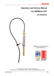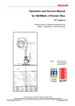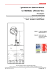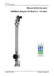
1
Operation and Service Manual for TS 13100 / TS 13101 / TS 13102 / TS 13104 / TS 13108 Intrinsically Safe Digital Thermometer Note: before using the instrument please read this book. This document is subject to changes without notice. Check updates on www.tanksystem.com or contact us at [email protected] 50444/ONECAL/1306 ONECAL This page intentionally left blank 50444/ONECAL/1306 2 ONECAL 1. Table of contents 1. Table of contents ________________ 3 6.6 Automatic shut off ______________ 16 2. General information _____________ 4 6.7 Changing the temperature scale C/F or the resolution 0.1° / 0.01° ____________ 17 2.1 Disclaimer ______________________ 4 2.2 Shipment note ___________________ 4 2.3 Initial inspection _________________ 4 2.4 Documentation discrepancies ______ 4 2.5 Warranty ______________________ 4 6.10 Saving the current temperature _ 19 2.6 Certification ____________________ 5 6.11 Showing the average temperature 20 2.7 Spare parts _____________________ 5 6.12 Scrolling up the saved data _____ 20 2.8 Service and Repair _______________ 5 6.13 Deleting one data point_________ 20 3. Worldwide Service Stations network 7 6.14 Erasing all data _______________ 20 4. Recommendation for safe use ______ 9 5. Description____________________ 10 5.1 6.8 Ullage distance _________________ 18 6.9 Taking a temperature reading ____ 19 6.9.1 6.9.2 7. A smart thermometer ___________ 10 5.1.1 General _______________________ 10 5.1.2 One point calibration_____________ 10 5.1.3 High standard in accuracy, repeatability and reproducibility ______________________ 10 Range up to 163 °C (325 °F) ______ 19 Range over 163 °C (325 °F) _______ 19 Care and maintenance __________ 21 7.1 Care __________________________ 21 7.2 Changing the battery ____________ 21 7.3 Changing the cable with cable holder assembly ____________________________ 22 7.4 Changing the sensor _____________ 23 5.2 Grounding cable with clip ________ 12 7.5 Changing the electronic box ______ 23 5.3 Sensor ________________________ 12 7.6 Temperature calibration _________ 23 7.7 Verification & calibration of the offset 24 5.3.1 5.3.2 5.3.3 Temperature probe ______________ 12 Resistance and response time ______ 12 Connection to the cable ___________ 12 5.4 Load for viscous liquids (option) __ 12 5.5 Cable and frame ________________ 13 5.6 Electronic box __________________ 13 5.7 Carrying belt __________________ 13 5.8 Carrying box (option) ___________ 14 6. 7.7.1 7.7.2 7.7.3 7.7.4 7.7.5 Operation _____________________ 15 6.1 6.1.1 6.1.2 6.2 Installing the battery ____________ 15 6.3 Basic rules concerning the 5-key control pad __________________________ 16 Basic rules concerning the display _ 16 6.5 Switching on the thermometer ____ 16 50444/ONECAL/1306 Storage of HERMetic devices _____ 26 7.9 Recycling of HERMetic devices ___ 26 Trouble shooting _______________ 27 8.1 Personal Protective Equipment _____ 15 Grounding the equipment _________ 15 6.4 7.8 8. Safety _________________________ 15 3 A smart thermometer ____________ 24 Equipment required _____________ 24 Preparing the Ice Point bath _______ 24 Calibrating the thermometer_______ 25 Recovering the previous calibration data 25 Warning and error messages _____ 27 9. Specification __________________ 28 10. Drawings _____________________ 29 10.1 Flowchart____________________ 29 10.2 Spare parts __________________ 30 ONECAL 2. General information 2.1 Disclaimer 2.5 24 months after delivery ex works. This manual is designed and written to provide information with regard to the subject matter involved. Enraf Tanksystem SA makes no warranty, express or implied, that it is fit for any purpose whatsoever; or to the absolute sufficiency of the material presented. The Vendor undertakes to remedy any defect resulting from faulty design, materials or workmanship. The Vendor's obligation is limited to the repair or replacement of such defective parts by his own plant or one of his authorised service stations. The Purchaser shall bear the cost and risk of transportation of defective parts and repaired parts supplied in replacement of such defective parts. Enraf Tanksystem SA assumes no responsibility for any inaccuracies in reproduction or errors in interpretation of any authority. Enraf Tanksystem SA reserves the right to modify or amend this manual, without prior notification, but Enraf Tanksystem SA assumes no responsibility to update or issue corrections. 2.2 This warranty does not apply to which by their nature are deterioration or consumption service, and which must be replaced on a routine basis. Shipment note The following parts should be included in the shipment: - 1 instrument; - 1 battery in the electronic box or separate; - 1 carrying belt; - 2 Allen keys (1.5 mm and 2 mm); - 1 Operation and Service Manual; - 1 Quick Reference Pocket Guide. 2.3 Initial inspection The Purchaser shall notify by fax, telex or in writing of any defect immediately upon discovery, specifying the nature of the defect and/or the extent of the damage caused thereby. Where no other conditions have been negotiated between the Vendor and the Purchaser "General Conditions 188" of United Nations shall apply. This instrument has been certified as Intrinsically Safe Instrumentation for only those classes or categories of hazardous areas stated on the instrument label, bearing the mark of the applicable approval authority. No other usage is authorised. Documentation discrepancies The design of the instrument is subject to continuous development and improvement. Consequently, the instrument may incorporate minor changes in detail from the information contained in the manual. 50444/ONECAL/1306 those items subject to in normal cleaned, or When returned to Enraf Tanksystem SA equipment must be contamination-free. If it is determined that the Purchasers equipment is contaminated, it will be returned to the Purchaser at the Purchasers expense. Contaminated equipment will not be repaired, replaced, or covered under any warranty until such time that the Purchaser decontaminates the said equipment. Check the contents of the shipment for completeness and note whether any damage has occurred during transport. If the contents are incomplete, or if there is damage, do not use the device. A claim should be filled out with the carrier immediately, and Enraf Tanksystem SA Sales or Service organisation should be notified in order to facilitate the repair or replacement of the instrument. 2.4 Warranty Abuse including rough handling, mechanical damage, electrical damage, operation, alteration, or unauthorised repair or component replacement by the Purchaser will void this guarantee and may 4 ONECAL China: NEPSI GYJ12.1052X Ex ia IIB T4 Ga impair the intrinsic safety of the instrument. In particular it is not allowed to repair electronic circuits. This warranty is expressly in lieu of any and all other warranties and representations expressed or implied, and all other obligations or liabilities on the part of the Vendor (Enraf Tanksystem SA) including but not limited to, the warranty of merchantability or fitness for a particular purpose. Russia: GOSGORTECHNADZOR 0ExiaIIBT4X If you need any specific certificate please contact: Enraf Tanksystem SA Rue de l'industrie 2 1630 Bulle, SWITZERLAND In no event shall Enraf Tanksystem SA be liable for indirect, incidental or consequential loss or damage or failure of any kind connected with the use if its products or failure of its products to function or operate properly. Telephone Telefax E-mail Web site Enraf Tanksystem SA do not assume the indemnification for any accident or damage caused by the operation of its product and the warranty is limited to the replacement of parts or complete goods. 2.6 2.7 : +41-26-91 91 500 : +41-26-91 91 505 : [email protected] : www.tanksystem.com Spare parts When ordering spares identify the spare part by TS number and description. Refer to section 10.2. Certification Some spares might be repairable; in this case send the part(s) to any authorised service center or to the factory. Enraf Tanksystem SA is an ISO 9001 certified company by Intertek. In case of urgency, complete replacement units can be made available. Contact the factory or nearest Service Station for details. The equipment has been approved for the electrical intrinsic safety by the following authorities: 2.8 Service and Repair The customer is responsible for any freight and customs clearance charges. If units are sent on a "freight collect" the charges will be invoiced to the customer. Europe: BASEEFA BAS 00 ATEX 1014X/1 II 1 G Ex ia IIB T4 Ga When returning units or parts for repair to the factory please fill out a service request form (see next page). The serial number (OXnnn) and the year of production (nnnn) are printed on the rear of the electronic box USA: Factory Mutual Class I, Division 1, Groups C&D, T4 Class I, Zone 0, AEx ia IIB T4 International: BASEEFA When returned to Enraf Tanksystem SA equipment must be contamination-free. If it is determined that the customers equipment is contaminated, it will be returned to the customer at the customers expense. Contaminated equipment will not be repaired until such time that the customer decontaminates the said equipment. IECEx BAS 12.0031X Ex ia IIB T4 Ga 50444/ONECAL/1306 5 ONECAL Service Request Customer's address: .............................................................................. ................................................................................................................ ................................................................................................................ ................................................................................................................ Contact name:......................................................................................... Telephone: .............................................................................................. Telex: ....................................................................................................... Fax: ......................................................................................................... Type of unit or part: ................................................................................. ................................................................................................................. Serial number: ...O..................................Year:.......................................... Short description of trouble: ..................................................................... .................................................................................................................. .................................................................................................................. .................................................................................................................. Do you want a quotation before repair is started:..........yes / no............. Repaired unit has to be returned to the following address: .................................................................................................................. .................................................................................................................. .................................................................................................................. For the Attention Of: .................................................................................................................. 50444/ONECAL/1306 6 ONECAL 3. Worldwide Service Stations network The updated list can be found on our website www.tanksystem.com COUNTRY ADDRESS TELEPHONE/FAX/E-MAIL SWITZERLAND ENRAF TANKSYSTEM SA 2, rue de l'Industrie CH-1630 BULLE Tel : +41-26-91 91 500 Fax : +41-26-91 91 505 [email protected] CANADA PYLON ATLANTIC A Div. Of Pylon Electronics Inc. 31 Trider Crescent., DARTMOUTH, N.S. B3B 1V6 Tel : +1-902-4683344 Fax : +1-902-4681203 [email protected] CHINA HUA HAI EQUIPMENT & ENGINEERING Tel : +86-21-68183183 CO LTD Fax : +86-21-68183115 Factory 7, Lane 1365, East Kang Qiao Road [email protected] Kang Qiao Industrial Zone, Pu Dong SHANGHAI, P.C. 201315 GERMANY CHRISTIAN BINDEMANN MARINE TECHNICAL SERVICES Antonie-Möbis-Weg 4 HAMBURG 2523 Tel : +49-40-41918846 Fax : +49-40-41918847 [email protected] GREECE SPANMARIN 86, Filonos Street GR-185 36 PIRAEUS Tel : +30-210-4294498 Fax : +30-210-4294495 [email protected] JAPAN DAIWA HANBAI CORPORATION LTD 2-10-31, Mitejima, Nishiyodogawa-ku OSAKA 555-0012 Tel : +81-6-64714701 Fax : +81-6-64729008 [email protected] KOREA World Ocean CO., LTD Rm1001, Hae-deok Bldg., 1212-11 Choryang-dong Dong-Gu BUSAN Tel : +82-51-462-2554/5 Fax : +82-51-462-0468 [email protected] MEXICO URBAN DEL GOLFO SA DE CV Julian Carrillo No. 709 Nte. COL. LOS MANGOS 89440 Cd. MADERO, Tamps, MEXICO Tel : +52-833-2170190 Fax : +52-833-2170190 [email protected] NETHERLANDS B.V. TECHNISCH BUREAU & BELGIUM UITTENBOGAART Brugwachter 13 NL-3034 KD ROTTERDAM 50444/ONECAL/1306 Tel : +31-10-4114614 Fax : +31-10-4141004 [email protected] 7 ONECAL The updated list can be found on our website www.tanksystem.com COUNTRY ADDRESS TELEPHONE/FAX/E-MAIL PORTUGAL CONTROLIS, Lda. Rua Conceição Sameiro Antunes, 26-E Cova da Piedade 2805-122 – Almada Tel : +351-21-2740606 Fax : +351-21-2740897 [email protected] RUSSIA NPP "GERDA" Vilisa Latsisa str. 17 Building 1 125480 MOSCOW Tel : +7-495-7558845 Fax : +7-495-7558846 [email protected] SINGAPORE HUBBELL INT'L (1976) PTE LTD 322 Thomson Road SINGAPORE 307665 Tel : +65-6-2557281 Tel : +65-6-2550464 Fax : +65-6-2532098 [email protected] SPAIN E.N.I. Electronica y Neumatica Industrial, S.A. C/Jon Arrospide, 20 (Int.) 48014 BILBAO Tel : +34-94-4746263 Fax : +34-94-4745868 [email protected] SWEDEN INSTRUMENTKONTROLL Lars Petersson AB Varholmsgatan 1 414 74 GÖTEBORG Tel : +46-31-240510 Tel : +46-31-240525 Fax : +46-31-243710 [email protected] TURKEY YEDI DENIZ Setustu, Izzetpasa Yok.1 TR 34427 Kabatas ISTANBUL Tel : +90.212.251 64 10 / 3 lines Fax : +90.212.251 05 75 [email protected] [email protected] UNITED ARAB EMIRATES MARITRONICS TRADING L.L.C. P.O. Box 6488 Shed # 72, Jadaf Ship Docking Yard DUBAI Tel : +971-4-3247500 Fax :+971-4-3242500 [email protected] UNITED KINGDOM ENERGY MARINE (INTERNATIONAL) LTD. Tel : +44-1525-851234 12 Clipstone Brook Industrial Estate Fax :+44-1525-852345 Cherrycourt Way [email protected] LEIGHTON BUZZARD, BEDS, LU7 4TX U.S.A / TEXAS HONEYWELL HERMETIC 4522 Center Street DEER PARK, TX 77536 50444/ONECAL/1306 Tel : +1-281-930 1777 Fax : +1-281-930 1222 Toll free call in the USA: 1-800-900 1778 [email protected] 8 ONECAL 4. Recommendation for safe use 1. This Operation and Service Manual is a guide in order to help the user to operate the instrument safely and correctly. 2. Nevertheless the maker disclaims all responsibility and liability for damage resulting from the use of the equipment regardless of the cause of the damage. 3. Attention is drawn to the possible hazard due to the fact that this equipment is to be used under open tank gauging conditions. Therefore the operator may be exposed to vapors and/or liquid splash. One must wear the personal protective equipment appropriate to the liquid the temperature of which is to be measured. Refer to the appropriate Material Safety Data Sheet (MSDS) and/or other site specific instructions. 4. Attention is drawn to the possible hazard due to electrostatic charges which may be present in the tank. This may happen in particular with static accumulator liquids, i.e. liquids that have low conductivity of 50 picoSiemens/metre (pS/m) or less. 5. It is very important that the instrument is earthed to the tank before the probe is introduced into the tank, and remains grounded until after complete withdrawal from the tank. The instrument should be grounded by means of the grounding cable and clip provided. 6. It is anticipated that the user will have specific operating methods laid down to ensure safety when using this type of apparatus. In this case the user's instructions shall be strictly observed. 7. In the absence of such instructions the following should be noted: 7.1. If the sensor probe is to be lowered into the tank via a grounded metal stilling well or sounding pipe that reaches below the liquid surface, or if the tank has a floating roof that is fully floating (and is in electrical continuity with the tank shell), then measuring the temperature is permissible at any time with no restriction. 7.2. In any other circumstances where a flammable vapor may be present, the following precautions should be taken: 7.2.1. If the cargo is not a static accumulator liquid, i.e. its conductivity is more than 50 pS/m, then measuring the temperature is permitted provided that the instrument is properly grounded and earthed before the temperature probe is inserted into the tank and remains earthed until the temperature probe has been removed from the tank. 7.2.2. If the cargo is a static accumulator liquid, i.e. its conductivity is less than 50 pS/m, then measuring the temperature is permitted provided that: 7.2.2.1. 7.2.2.2. The instrument is properly grounded and earthed before the temperature probe is inserted into the tank and remains earthed until the temperature probe has been removed from the tank, andThe apparatus is not introduced into a tank until at least 30 minutes have elapsed after completion of any loading or mixing operation or stopping the injection of inert gas. 7.3. For further guidance refer to International Safety Guide for Oil Tankers and Terminals (ISGOTT), ISBN 1 85609 291 7, Fith Edition 2006 or consult the appropriate Legislative Authority for the installation. 8. Warning: Substitution of components may impair the intrinsic safey. Change the battery only in a safe area; Use only an approved battery. To prevent ignition hazard, avoid impact or friction of the device aluminium box. 9. This product and its use is / may be related to international, national, local or company regulations or standards. It is the customer / user responsibility to ensure that the way to use the device complies with such applicable regulations or standards. 50444/ONECAL/1306 9 ONECAL 5. Description 5.1 A smart thermometer 5.1.1 General The thermometer is a hand-held portable digital instrument of the latest generation, designed specifically for use in hazardous locations with outstanding characteristics regarding safety, accuracy, ease of operation, reliability and cost efficient maintenance. It is very user friendly and easy to calibrate: - the is modular; the exchange of parts is extremely easy and cost efficient. No special training or tools are required. - changing the cable does not require the instrument to be re-calibrated, - changing the sensor requires only an offset calibration, i.e. the ice point calibration 5.1.2 One point calibration Temperature calibration and verification are the most important points for keeping a good accuracy, but in most cases these procedures involve costly equipment, are time consuming and therefore quite expensive. stands for: one reference point only for calibration. No special tool or training is required for calibrating this thermometer. The temperature/resistance curve of the Platinum Resistance Temperature Detector (Pt-RTD) is digitally stored in a micro-controller and cannot be changed by the user. The relationship between resistance and temperature is then used to calculate the temperature reading. Therefore the calibration consists of the adjustment of the offset scale value at 0,0 °C. This reference point is the water triple point (ice point), which can be easily and universally reproduced. See 7.7.3. During the calibration procedure the automatically checks the accuracy and stability of the reference temperature. In other words the will not accept a new calibration if this is not done properly. 5.1.3 High standard in accuracy, repeatability and reproducibility The onecal thermometer is specifically designed to meet the highest accuracy standards (ISO 4268, API Manual of Petroleum Measurement Standards Chapter 7) that are commonly accepted best oil industry practice. The goal of the measuring routine is to determine as accurately as possible the Pt-RTD resistor value and to calculate the corresponding temperature. For achieving such a high standard in accuracy, repeatability and reproducibility the resistance of the cable and instrument electronics is continuously measured and compensated for, i.e. a variation of the cable or circuitry resistance due to temperature change does not affect the accuracy and a cable change does not require a new calibration. The measurement routine is totally under the control of the micro-controller. A high precision resistor is used as the reference to calibrate the measuring chain. Figure 1 shows the main features of the 50444/ONECAL/1306 . 10 ONECAL Figure 1 50444/ONECAL/1306 11 ONECAL 5.2 Grounding cable with clip This device is very important for the safe operation of the instrument. As static electricity can cause an explosion if a flammable vapor is present, it is mandatory to ground the by means of the grounding cable and clip. Refer to section 3. 5.3 Sensor 5.3.1 Temperature probe The temperature probe is a Platinum Resistance Temperature Detector (Pt-RTD) located close to the end of the protective probe sheath. This Pt-RTD constitutes the core of the thermometer; and it is therefore specially selected in order to ensure only those individuals that perform to a very strict specification and show the highest level of accuracy, long term stability and reliability over the range of temperature are used. 5.3.2 Resistance and response time The sensor is specially designed to combine a very good shock resistance, with a 6 mm diameter probe sheath, and a quick response time. It is made in stainless steel to withstand most aggressive chemicals. The has a typical response time (time to achieve 90% of a step change in temperature) of less than 15 seconds in water and 35 seconds in lubricating oil, under dynamic conditions. 5.3.3 Connection to the cable The sensor is equipped with a genuine connector, thus connecting it to the cable could not be more easy. There is no need for special tools, soldering, sealing, etc. Just plug in and go! 5.4 Load for viscous liquids (option) A special extra load (300 g) can be provided as an option, in case very viscous liquids are measured. It is very easy to install. Two screws (Allen key 2 mm) secure it on the sensor . Order Number TS 13071 (load delivered with its holder kit to fix on the cable holder) Figure 2 50444/ONECAL/1306 12 ONECAL 5.5 Cable and frame This is a shielded coaxial two conductors cable, with an FEP jacket that withstands most chemicals. It can be easily disconnected from both the sensor and the electronic box if it needs to be replaced. The replacement of the cable does not necessitate the recalibration of the , as its resistance is automatically checked and balanced by the micro-controller. See also section 5.6. The frame is made in antistatic polyamide. It is ergonomic and rugged for easy and safe cable storage. One loop is approximately 0.7 m (2 ft 3"), 1.5 loop is approximately 1 m (3 ft 4"), so it is easy to correctly position the sensor at the desired positions within the tank contents by simply counting the number of cable loops unwound. See also section 6.8. Note: the cable cannot be dismounted or removed from the frame, see 7.3. 5.6 Electronic box The electronic box contains the 5-keys control pad, the display and a circuit board. It is powered by a 9V battery. It is protected against dust and splashing water as per the IEC 529 standards (IP54). By pressing the 5-key control pad the user can select the temperature scale, the operating mode, and store up to 9 temperature measurements, or calculate the average temperature on selected data. See also section 6. The approved batteries are: - Zinc Carbon or Zinc Chloride: 6F22 or 6F22P - Alkaline Manganese: 6LR61, Duracell MN1604/ Procell PC1604 5.7 Carrying belt The is supplied with a special carrying belt. Figure 4 Figure 3 50444/ONECAL/1306 13 ONECAL 5.8 Carrying box (option) Available in option, this special box is fully cushioned and prevents the storage or carrying. of damage during Order Number is TS 13064. Figure 5 Figure 6 50444/ONECAL/1306 14 ONECAL 6. Operation 6.1 Safety 6.1.1 Personal Protective Equipment Appropriate safety precautions should be taken according to the hazard and toxicity of the liquid the temperature of which is to be measured. The purpose of the personal protective equipment is to prevent a hazardous material from coming into contact with the body, either directly to the skin or eyes, through inhalation of vapors or mists or by absorption through the skin. Appropriate respiratory protection and head, face, hand and foot protection shouls be worn prior to opening the hatch and using the . 6.1.2 Grounding the equipment Before opening the tank hatch attach the grounding clip to an electrically conductive grounded structure. Make sure that the surface which the clip is in contact with is electrically conductive. The shall be grounded until complete withdrawal of the temperature probe from the tank and closure of the hatch. Refer to section 3. 6.2 Installing the battery THIS MUST BE DONE ONLY IN A SAFE AREA. (1) Unscrew the 2 screws of the battery cover located at the rear face of the electronic box. (2) Check that the battery is approved, i.e. Duracell MN1604/ Procell PC1604 or any 6F22 or 6F22P. (3) insert the battery. (4) Put the cover back and tighten the screws. Figure 7 50444/ONECAL/1306 15 ONECAL 6.3 Basic rules concerning the 5-key control pad enter (E) on / off + - : activate the function : switch on / off : go into the menu or yes : quit the menu or no Keep the commands pressed until the action is displayed. The "off" key is not active in all menus. Press "-" to leave those menus before switching off the 6.4 . Basic rules concerning the display The degree mark "°" is regularly blinking in the measurement mode. The display is refreshed every second in the measurement mode. All other modes showing saved temperatures do not display the degree mark "°". The display is blinking when the temperature is between 163 °C ( 325 °F) and 200 °C (392 °F). 6.5 Switching on the thermometer Press "on". The following sequence is displayed automatically. on or The second. 6.6 is now ready for measuring the temperature, that is displayed and refreshed every Automatic shut off If there is no action on the automatically. 50444/ONECAL/1306 keyboard during 10 minutes the thermometer switches off 16 ONECAL 6.7 Changing the temperature scale C/F or the resolution 0.1° / 0.01° Press "+" twice, then "enter". Press "+" to switch from the temperature scale mode to the resolution mode. Temperature °C or °F: when "Temp" is displayed press "enter", then "+" to chose the scale. Press "-" 3 times to return to the measurement mode. Resolution 0.1° ou 0.01°: when " displ" is displayed press "enter", then "+" to chose the resolution. Press "-" 3 times to return to the measurement mode. 50444/ONECAL/1306 17 ONECAL 6.8 Ullage distance An approximate relation between the number of loops and the distance is given in the following table: Distance (m) Number of loops Distance (ft) 0,67 1 2ft 3" 1 1.5 2 2 4,5 3 5 4 6 8 11 6 8 18 9 20 11 24,5 12 14 10 31 15 16 12 15 36 18 19 42 21 46.5 22 23 51 24 54 17 25 19 28 62 30 66.5 21 23 31 32 72 33 73 34 35 77.5 25 37 82 27 40 89 42 93 29 43 44 31 33 50444/ONECAL/1306 97.5 46 47 104 49 108.5 51 113 18 ONECAL 6.9 Taking a temperature reading Make sure that the is properly grounded. See sections 3 and 6.1. Take the temperature probe and place it in the liquid to be measured. 6.9.1 Range up to 163 °C (325 °F) Select the location(s) at which measurements are to be made in accordance with established best oil industry practice (ISO 4268, API Manual of Petroleum Measurement Standards Chapter 7), and lower the sensor probe to the required level(s) by counting the number of cable loops unwound (Refer to section 6.8) to reach the required ullage distance(s). At each measurement location, raise and lower the probe by half a cable loop above and below the predetermined level to allow rapid equilibration of the sensor with the surrounding liquid. Observe the display and wait until the reading has stabilized before recording it or saving it (see section 6.10). The probe may be considered to have reached equilibrium with the surrounding liquid when the indicated temperature has not changed by more than 0,1C in approximately 30 seconds. If the temperature does not stabilize, continue to raise and lower the probe in the liquid for a longer time; and make sure that the lack of stability is not caused by the liquid itself. If multiple spot temperatures are required, repeat the procedure at each of the other predetermined levels. Note: when the extra load is used (refer to section 5.4), the time to reach equilibrium is longer. 6.9.2 Range over 163 °C (325 °F) In that range only surface temperatures are allowed, i.e. immersing the sensor by maximum 10 cm or 4 inches. In that range the display of the temperature is blinking. 6.10 Saving the current temperature From the measurement mode press "enter" to save the temperature. The index in the memory appears on the left of the LCD display, as follows. up to measure 9 s E Up to 9 individual measurements can be stored. If 9 measurements are already stored, the memory is full and the following screen is displayed: After saving, the thermometer returns automatically to the measurement mode. 50444/ONECAL/1306 19 ONECAL 6.11 Showing the average temperature From the measurement mode, press "+", and then "enter", to display the average temperature. 6.12 Scrolling up the saved data From the average temperature display, press "enter", and then by pressing "+", scroll up the saved data. 6.13 Deleting one data point It is possible to delete one or more data point(s), one by one. From the average temperature display, press "enter", then "+" as many times as necessary to get the data point to delete, then press "enter". Press "enter" again to erase. Press "+" to confirm. See below an example where data point n°2 is deleted. The recalculates the average temperature of the remaining data. 6.14 Erasing all data To clear the memory, i.e. erasing all the saved data (up to 9 individual data points), from the measurement mode press "-", then "enter", and then "+". 50444/ONECAL/1306 20 ONECAL 7. Care and maintenance 7.1 Care Clean the instrument of any excess of liquid after each use. Wipe the cable after each use. Check regularly the continuity of grounding by measuring the electrical resistance between the sensor and the clip of the grounding cable. The resistance should not exceed 10 ohm. Check regularly the sensor, the cable and the grounding cable for any kink, scratch, cut or other visible damage. Store the equipment in a dry location. 7.2 Changing the battery THIS MUST BE DONE ONLY IN A SAFE AREA. (1) Unscrew the 2 screws of the battery cover located at the rear face of the electronic box. (2) Replace the battery. Use only approved batteries, i.e. Duracell MN1604/ Procell PC1604 or any 6F22 or 6F22P. (3) Put the cover back and tighten the screws again. Figure 8 50444/ONECAL/1306 21 ONECAL 7.3 Changing the cable with cable holder assembly The cable cannot be removed or dismounted from the frame. If the cable needs to be replaced it is therefore necessary to change the subassembly (cable + cable frame) as follows: (1) Unscrew and remove the plug located on the front face of the electronic box. Figure 9 (2) Remove the electronic box from the holder by pressing on top of the rear of it, in order to clip it out of the frame. (3) Unscrew and gently pull the connector from the sensor tube. See Figure 10. Figure 10 (4) (5) (6) (7) On the new sub assembly (cable + frame) connect the cable to the sensor and tighten it with the screw. Mount the electronic box into the frame. Connect the plug to the electronic box and secure it with the screw. Switch the on. The electronic circuit checks and compensates automatically the resistance of the new cable. Therefore changing the cable does not affect the calibration. (8) Verify the correct functionning of the by measuring a known temperature. (9) The is ready to work again. 50444/ONECAL/1306 22 ONECAL 7.4 (1) (2) (3) (4) Changing the sensor Unscrew and gently pull the connector from the sensor tube. See Figure 10. Connect the new sensor. Secure it with the screw. Carry out the one point verification as per 7.7. The is ready to work again. 7.5 Changing the electronic box (1) Unscrew and remove the grounding cable from the rear of the electronic box. See Figure 11. (2) Unscrew and remove the plug located on the front face of the electronic box. See Figure 9. (3) Remove the electronic box from the holder by pressing on top of the rear face, in order to clip it out of the frame. (4) Clip the new electronic box into the frame. (5) Connect the plug to the electronic box and secure it with the screw. (6) Screw the grounding cable onto the correct location on the rear of the electronic box, as shown on Figure 11. The grounding cable shall be held on the left of the plastic finger Figure 11 (7) Check with an Ohmmeter the resistance between the grounding cable clip and the body of the temperature probe. It shall not exceed 10 ohm. (8) Carry out the one point verification as per section 7.7. (9) The is ready to work again. 7.6 Temperature calibration The is calibrated at the factory, i.e. the temperature/resistance curve of all the specially selected Pt RTDs is digitally stored in every electronic box so no further calibration is required. It is still necessary to check the regularly for any drift of the offset. 50444/ONECAL/1306 23 ONECAL 7.7 Verification & calibration of the offset 7.7.1 A smart thermometer The is very user friendly and easy to calibrate. Only one reference point is necessary to calibrate the instrument. Moreover the automatically checks the accuracy and stability of the reference temperature. In other words the will not accept a new calibration if the following conditions are not fulfilled: - the measured reference temperature exceeds 0.2 °C - the temperature stability exceeds 0.03 °C During the calibration process the keeps the previously recorded calibration data, so that in case of a procedural error it is always possible to revert to the previous calibration.. 7.7.2 Equipment required - 7.7.3 A Dewar flask or any vacuum flask, approximately 8 cm in diameter and 36 cm deep. Ice, preferably made from distilled water. Water, preferably distilled and precooled. Preparing the Ice Point bath (1) Shave or crush the ice into small pieces, avoiding direct contact with the hands or any unclean object. The pieces shall be no more then 5 mm. (2) Fill the Dewar flask with the crushed ice and add sufficient water to form a slush, just filling the voids between ice particles but not enough to float the ice. (3) Insert the sensor, packing the ice gently about it. (4) Let it stand for half an hour to permit the sensor temperature, the ice particles and the water to equilibrate. (5) As the ice melts it will be necessary to drain off some water and add more crushed ice. Gently stir the ice with the sensor periodically to assist equilibration. IMPORTANT NOTE: Attention to detail during the preparation of the Ice Point bath is critical to the accuracy and quality of the offset calibration. Therefore be advised that the will accept a new calibration only if the following conditions are fulfilled: - the proposed correction of the offset is within 0.2 °C ( 0.4 °F) compared to the true zero of the Pt-1000 resistance, and - the stability of the temperature is within 0.03 °C ( 0.06 °F). 50444/ONECAL/1306 24 ONECAL 7.7.4 Calibrating the thermometer (6) After 30 minutes have elapsed, gently stir the bath with the sensor again to ensure complete equilibration of temperature. (7) Switch on the . (8) Press "+" 3 times to call up the calibration menu. (9) Press "enter" to activate the function. When in this calibration routine the temperature is displayed to two decimal places of a degree. (10)Observe the reading. The temperature must be stable, i.e. within 0.03 °C ( 0.06 °F). (11)By pressing "enter", store at least 3 readings, up to 9. Wait 30 seconds between each reading in order to check the bath stability. (12)When at least 3 individual readings are stored (but no more than 9), press "+" to activate the offset calculation process. (13)To store the new offset correction press "+". The following sequences will be displayed during the process. (14)Press "-" twice to go back to the measurement mode. (15)If any other message is displayed refer to section 8. 7.7.5 Recovering the previous calibration data If for any reason one wants to return to the previous calibration, this may be achieved from the calibration menu as follows: (1) Press simultaneously the keys "enter" and "+", then "+", and "+". 50444/ONECAL/1306 25 ONECAL 7.8 Storage of HERMetic devices For a proper storage of HERMetic products (UTImeter, Sampler, Thermometer and related spareparts…), we recommend: - Clean the devices after use, - Remove batteries for prolonged storage, - Store batteries in a dry and cold location, - Store the goods in a safe, dry and dust free location with an ambient temperature between +5°C to +45°C. 7.9 Recycling of HERMetic devices Equipment does not contain any dangerous materials inside which can harm the environment and people health during normal use or disposal. However the utilization and recycling of the equipment after the end of its life must be implemented by an authorized organization in accordance to local legislation. Do not throw in rubbish but recycle wastes in accordance to environmental / local rules. 50444/ONECAL/1306 26 ONECAL 8. Trouble shooting 8.1 Warning and error messages (blinking message) The battery voltage is low, temperature readings are still valid, but the battery needs to be changed soon. The battery voltage does not guarantee the temperature integrity. Change the battery, ONLY IN A SAFE AREA. 1) There is no probe or no cable attached to the . 2) The probe or the cable is not properly installed. Check the connections. 3) The probe or the cable is malfunctioning. Check for kinks, breaks, etc. The probe or cable is malfunctioning. Check the connections, and check the cable for mechanical damage. The current temperature is out of the i.e. > 200 °C or > 392 ° F. range, The current temperature is out of the i.e. < - 40 °C or < - 40° F. range, Not enough temperature readings stored during the calibration procedure. The temperature reference is out of range. Check the quality of the ice point bath. It should be (0.0 °C 0.2 °C), (32.0 °F 0.4 °F). The reference temperature is not stable enough. Check that the stability of the ice point bath is within ( 0.03 °C), ( 0.06 °F). You have pressed "enter" although the current temperature is out of the range. The memory is full. To store other individual readings first delete some data or erase them all. The does not shut off and looks as locked on The shuts off automatically 50444/ONECAL/1306 Press (-), then (+), the onecal returns in measurement mode. Press "off" again. If the problem persists, disconnect and reconnect the battery, only in a safe area. There was no action on the during the last 10 minutes. The shuts off automatically to save the battery. 27 ONECAL 9. Specification General Specification Guarantee 2 years Measurement range -40 °F to 325 °F / -40 °C to 163 °C Sensor temperature range -40 °F to 392 °F / -40 °C to 200 °C Ambient temperature range -20 °C to 40 °C Resolution 0.1° or 0.01° selectable Temperature scale °F / °C, selectable Accuracy exceeds API MPMS Chapter 7 -40 °F to -22 °F / -40 °C to -30 °C 0.4 °F / 0.25 °C -22 °F to 212 °F / -30 °C to 100 °C 0.2 °F / 0.1 °C 212 °F to 325 °F / 100 °C to 163 °C 0.4 °F / 0.25 °C Repeatability exceeds API MPMS Chapter 7 0.2 °F / 0.1 °C -40 °F to 325 °F / -40 to 163 °C Calibration digital, one point only (ice point 32 °F / 0 °C) Memory up to 9 individuals Display LCD 8 digits, 10 mm character height Power approved 9 V battery Battery saving automatic shut off 10 minutes after latest action Battery life approx. 100 hours Low battery indication on LCD display Overall dimensions length x width x depth 13.2 " x 8 " x 3.7 " / 336 mm x 202 mm x 94 mm Weight with 75 ft / 22.8 m cable < 3 lbs / 1.4 kg Probe size 0.64 " / 16 mm diam., 6 " / 150 mm long Probe material Stainless steel 316L Cable length 7ft / 2 m, 25 ft / 7.6 m, 50 ft / 15.2 m, 75 ft / 22.8 m, 110 ft / 33.5 m Cable material FEP jacket Instrument protection IP 54 Frame material antistatic polyamide base Electronic box material coated aluminium Temperature sensor Pt-1000 RTD element Maintenance modular design / easy exchange of parts Hazardous environments approvals IECEx (International) Ex ia IIB T4 Ga ATEX (Europe) II 1 G Ex ia IIB T4 Ga FM Approvals (USA) Class I, Division 1, Groups C&D, T4 Class I, Zone 0, AEx ia IIB T4 NEPSI (China) Ex ia IIB T4 Ga GOSGORTECHNADZOR (Russia) 0ExiaIIBT4X Specification subject to change without notice. 50444/ONECAL/1306 28 ONECAL 10. Drawings 10.1 Flowchart Version 2.xx Keyboard Basic Rules : Enter (E) : Execute the Command + : Unroll Menu (Confirm) : Quit the Menu E - Automatic Shut Off 10 min E - + - + - + E E + (Idx + 1) - - + - E - E - + - + Yes E E + - PTB ? - + E - + - No + - E E+ - E + Messages : Battery Cable-RTD Memory - + - Automati c Shut Off active + Check values & Battery Reading out of range + Calibration Readings (up to 9, at least 3) Automatic Shut Off inactive Error Code : Error 12 : Calibration Readings < 3 Error 13 : OFFSET out of range Error 14 : Unstable Reference Bath Error Code EEPROM: Error 01 : Read Temp Unit Error 02 : Write/Read Temp Unit Error 03 : Write/Read Data Error 04 : Write/Read Data Index Error 05 : Read Data Index out of range Error 06 : Read Data Figure 12 50444/ONECAL/1306 29 ONECAL 10.2 Spare parts When ordering spare parts please identify them by their description and TS number. Indicate the serial number and the year of production of the thermometer (printed on the rear of the electronic box). If the cable holder must be changed it is necessary to order 2x "half frame" TS 13035 and 4x rods TS 13049. The cable is always delivered with the cable holder, this is to prevent damage. Check the cable length required and order accordingly. The carrying belt number is TS 13058. Figure 13 50444/ONECAL/1306 30 ONECAL