1
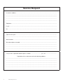
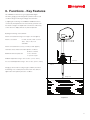
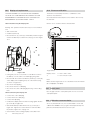
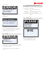
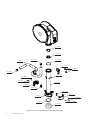
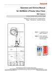
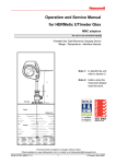
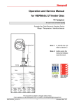
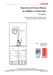
Operation and Service Manual for HERMetic TOMSYS for use in non corrosive liquids Portable digital automatic gas tight Topping-off monitoring system MED-D Note 1: to identify the unit refer to section 2 Note 2: before using the instrument please read this book. Note 3: this document is subject to changes without notice. Check updates on www.tanksystem.com or contact us at [email protected] This page intentionally left blank 2 www.tanksystem.com 1. Table of contents 1. TABLE OF CONTENTS..................................................... 3 2. IDENTIFICATION OF YOUR EQUIPMENT....................... 4 2.1 SERIAL NUMBER..................................................... 4 2.2 ABBREVIATIONS...................................................... 4 9.3.1.3 Menu Language....................................... 25 9.3.2 Battery status.............................................. 25 9.3.3 Sensor parking............................................ 25 9.4CHECKING THE FUNCTIONS BEFORE USING THE UNIT............................................................... 26 3. GENERAL INFORMATION................................................ 6 9.4.1 Battery........................................................ 26 3.1 SHIPMENT NOTE..................................................... 6 9.4.2 Level monitor and Ullage detector............... 26 3.2 INITIAL INSPECTION................................................ 6 3.3 DOCUMENTATION DISCREPANCIES....................... 6 3.4 WARRANTY............................................................. 6 3.5 CERTIFICATION........................................................ 7 3.5.1 Ex Certificates............................................... 7 3.5.2 Classification society certificate..................... 7 3.6 SPARE PARTS.......................................................... 7 3.7 SERVICE AND REPAIR............................................. 7 4. WORLDWIDE SERVICE STATIONS NETWORK.............. 9 5. RECOMMENDATION FOR SAFE USE........................... 10 6. FUNCTIONS - KEY FEATURES...................................... 11 7. DESCRIPTION................................................................ 12 9.5 INSTALLATION OF THE UNIT................................. 26 9.6 LEVEL MONITORING............................................. 26 9.7 ULLAGE DETECTION............................................. 26 9.8 TRANSPORTATION................................................ 26 10. CARE AND MAINTENANCE........................................... 27 10.1 SAFETY WARNING................................................. 27 10.2 CARE..................................................................... 27 10.3 CHECKING THE BATTERY..................................... 27 10.4 BATTERY REPLACEMENT..................................... 27 10.5 DISPLAY UNIT REPLACEMENT.............................. 28 10.5.1 Disconnecting the display unit................... 28 10.5.2 Connecting the display unit....................... 28 10.6DISTANCE VERIFICATION...................................... 28 10.7 PLASTIC PARTS..................................................... 28 10.8 CALIBRATION RECOMMENDATIONS.................... 28 7.1 GENERAL............................................................... 12 7.2 TOMSYS SENSING PROBE................................... 14 7.3 TAPE...................................................................... 14 11. TROUBLE SHOOTING.................................................... 29 7.4 DISTANCE MEASUREMENT................................... 15 11.1 SAFETY WARNING................................................. 29 7.5 GAS TIGHTNESS................................................... 16 7.6 GASKETS............................................................... 16 11.2 EMERGENCY CRANK............................................ 29 7.7 HOUSING AND LID................................................ 16 11.3 POWER SUPPLY TROUBLES................................. 29 7.8 OTHERS................................................................. 16 11.4 TRANSMISSION TROUBLES.................................. 29 7.9 DEMO MODE FUNCTION....................................... 16 11.5SENSOR MOVING TROUBLES.............................. 30 8.EXAMPLES OF INSTALLATION OF THE GAUGING SYSTEM........................................................ 17 8.1 GENERAL............................................................... 17 8.2EXAMPLE OF INSTALLATION ON A PIPE, CONNECTOR Q2................................................... 18 9. OPERATION.................................................................... 20 9.1BASIC RULES CONCERNING THE 5-KEY CONTROL PAD...................................................... 20 9.2QUICK START........................................................ 21 9.2.1 Level monitoring.......................................... 21 9.2.2 Ullage detection.......................................... 21 9.2.3 Preset......................................................... 22 11.5.1 Moving trouble on the way down.............. 30 11.5.2 Moving trouble on the way up................... 30 11.6DISTANCE MEASUREMENT TROUBLES............... 30 11.7 SENSOR ERRORS................................................. 30 11.8 TILT ERRORS......................................................... 31 11.9VISUAL INSPECTION FOR DAMAGED OR MISSING PARTS.................................................................... 31 8.3EXAMPLE OF INSTALLATION ON THE DECK, CONNECTOR Q2................................................... 19 9.3SERVICE MENU..................................................... 24 9.3.1 Settings....................................................... 24 9.3.1.1 Distance measurement scale................... 24 9.3.1.2 Distance measurement resolution............ 24 12. SPECIFICATIONS........................................................... 32 13. SPARE PARTS................................................................ 33 13.1 HOW TO PROCEED............................................... 33 13.2 LIST OF PARTS DESCRIPTIONS............................ 33 13.3 SPARE PARTS DRAWINGS.................................... 33 14. VALVES DRAWINGS....................................................... 39 14.1 VALVES DRAWINGS LIST....................................... 39 14.2 DRAWINGS............................................................ 39 15 DECLARATION OF CONFORMITY................................ 51 3 2. Identification of your equipment 2.1 Serial number Identification plate Each HERMetic instrument is individually identified with a 6 digits serial number starting with the letter T, example T10025. This serial number is printed on the identification plate that is located on top of the device. See Figure 2-1. Figure 2-1 2.2 Abbreviations Some abbreviations are used to define the equipment. Refer to following table and to Figure 2-2. Abbreviation Meaning ETCE Special PTFE used for extruding FFKM Perfluoro rubber, special for chemical applications FKM Fluoro rubber for crude oil and some products applications NBR Acrylonitrile-butadiene rubber (nitrile rubber) PE Polyethylene PEHD Polyethylene High Density PFA Perfluoro alkoxyl alkane PTFE Polytetrafluoroethylene Q1 Connector 1” Q2 Connector 2” SS1 Stainless steel Storage tube 1” SS2 Stainless steel Storage tube 2” TEFZEL ETFE coating of the tape 4 www.tanksystem.com Mechanical housing Display unit Storage tube SS2 Quick connector Q2 Sensing probe TOMSYS Figure 2-2 5 3. General information 3.1 Shipment note The following parts should be included in the shipment: When returned to Enraf Tanksystem SA or any of its agreed Service Stations equipment must be contamination-free. If it is determined that the Purchasers equipment is • 1 instrument fitted out with six (6) batteries in the display; contaminated, it will be returned to the Purchaser at the • 1 Allen keys: 3 mm; Purchasers expense. Contaminated equipment will not be • 1 emergency crank, repaired, replaced, or covered under any warranty until • 1 Operation and Service Manual. such time that the said equipment is decontaminated by the Purchaser. 3.2 Initial inspection Check the contents of the shipment for completeness and note whether any damage has occurred during transport. Carry out the “Initial test” refer to 9.4 “Checking the functions before using The Purchaser shall notify by fax, email or in writing of any defect immediately upon discovery, specifying the nature of the defect and/or the extend of the damage caused thereby. the unit” to verify the good functioning. Where no other conditions have been negotiated between the If the contents are incomplete, or if there is a damage, do Vendor and the Purchaser “General Conditions 188” of United not use the device, a claim should be filled with the carrier Nations shall apply. immediately, and Enraf Tanksystem SA Sales or Service organization should be notified in order to facilitate the repair or replacement of the instrument. This instrument has been certified as Intrinsically Safe Instrumentation for only those classes or categories of hazardous areas stated on the instrument label, bearing the mark of the applicable approval authority. No other usage is 3.3 Documentation discrepancies authorized. The design of the instrument is subject to continuous Unauthorized repair or component replacement by the development and improvement. Consequently, the instrument Purchaser will void this guarantee and may impair the intrinsic may incorporate minor changes in detail from the information safety of the instrument. In particular it is not allowed to repair contained in the manual. electronic circuits. In no event shall Enraf Tanksystem SA be liable for indirect, 3.4 Warranty One (1) year after installation but max. 18 months after delivery ex works except batteries. The Vendor undertakes to remedy any defect resulting from faulty design materials or workmanship. The Vendor’s obligation is limited to the repair or replacement of such defective parts by his own plant or one of his authorized service stations. The Purchaser shall bear the cost and risk of transportation of defective parts and repaired parts supplied in replacement of such defective parts. 6 www.tanksystem.com incidental or consequential loss or damage or failure of any kind connected with the use if its products or failure of its products to function or operate properly. Enraf Tanksystem SA do not assume the indemnification for any accident or damage caused by the operation of its product and the warranty is limited to the replacement of parts or complete goods. 3.5 Certification 3.5.2 Classification society certiifcates The HERMetic TOMSYS is certified by following classification 3.5.1 Ex certificates societies: ABS Certificate of design assessment Enraf Tanksystem SA is an ISO 9001 certified company by QMI and MED-D certified company by Det Norske Veritas Certification GmbH. 3.6 Spare parts When ordering spares identify the spare part by TS number and description. Refer to section “Drawings”. Some spares might be repairable; in this case send the part(s) to any authorised service center or to the factory. The equipment has been approved for the electrical intrinsic safety by the following authorities : In case of urgency, complete replacement units can be made available. Contact the factory or nearest Service Station for details. IECEx Ex ia IIB T4 Ga -20°C < Ta < 50°C Standards used: IEC 60079-0, ed. 5.0 (2007-10), IEC 60079-11, ed. 5.0 (2006-07), IEC 60079-26, ed. 2.0 (2006-08) 3.7 Service and Repair The customer is responsible for any freight and customs clearance charges. If units are sent on a “freight collect” the charges will be invoiced to the customer. When returning units or parts for repair to the factory please fill ATEX II 1 G Ex ia IIB T4 Ga out a service request form (see next page). The serial number -20°C < Ta < 50°C (letter “T” followed by 5 digits) is printed on the identification Standards used: plate as shown on the Figure 2-1. EN 60079-0:2009, EN 60079-11:2007 When returned to Enraf Tanksystem SA equipment EN 60079-26:2007 must be contamination-free. If it is determined that the customers equipment is contaminated, it will be Factory Mutual returned to the customer at the customers expense. (FM Approvals) CL I, DIV 1, GP C & D, Tamb 50°C Contaminated equipment will not be repaired until such time that the customer decontaminates the said CL I, ZN 0, AEx ia IIB T4 Tamb 50°C Standards used: equipment. 3600:1998 (General) 3610:2010 (Instrinsic Safety) Regarding product compliance against standards updates or new standards, please refer to the Declaration of conformity. If you need a copy of any of these certificates please contact: Enraf Tanksystem SA Rue de l’industrie 2 1630 Bulle, SWITZERLAND Telephone : +41-26-91 91 500 Telefax : +41-26-91 91 505 Web site : www.tanksystem.com E-mail : [email protected] 7 Service Request Customer’s address: .................................................................................................................................. ..................................................................................................................................................................... ..................................................................................................................................................................... ..................................................................................................................................................................... ..................................................................................................................................................................... Telephone: .................................................................................................................................................. E-mail: ......................................................................................................................................................... Fax: ............................................................................................................................................................. Type of unit or part: .................................................................................................................................... ..................................................................................................................................................................... Serial number: ............................................................................................................................................ Short description of trouble: ...................................................................................................................... ..................................................................................................................................................................... ..................................................................................................................................................................... ..................................................................................................................................................................... Do you want a quotation before repair is started: . ............................... yes / no ................................... Repaired unit has to be returned to the following address: ..................................................................................................................................................................... ..................................................................................................................................................................... ..................................................................................................................................................................... ..................................................................................................................................................................... ..................................................................................................................................................................... 8 www.tanksystem.com 4. Service station network Service station network list can be found on our website at www.tanksystem.com. For repairs, please contact the after sales department at [email protected] or Send your device to Enraf Tanksystem SA Rue de l’Industrie 2 1630 Bulle Switzerland 9 5. Recommendation for safe use 1.This Operation and Service Manual is a guide in order 6.In the absence of such instructions the following should to help the user to operate the instrument to our best knowledge. be noted: 6.1. If a metal sounding pipe is fitted beneath the 2.Nevertheless the maker disclaims all responsibility and deck valve or tank is inerted, then ullaging, etc. is liability for damage resulting from the use of the equipment regardless of the cause of the damage. permissible at any time with no restriction. 6.2. If there is no sounding tube or tank is not inerted, the following precautions shall be taken: 3.Attention is drawn to the possible hazard due to electrostatic charges which may be present in the 6.2.1. If the cargo is not a static accumulator liquid, tank. This may happen in particular with static i.e. its conductivity is more than 50 pS/m, accumulator liquids, i.e. liquids which have low then ullaging is permitted provided that the conductivity of 50 picoSiemens/metre (pS/m) or less. instrument is properly grounded and earthed before the probe is inserted into the tank and 4.It is very important that the instrument is grounded to remains earthed until the probe has been the tank before the probe is introduced into the tank and remains grounded until after complete withdrawal from the tank. removed from the tank. 6.2.2. If the cargo is a static accumulator liquid, i.e. its conductivity is less than 50 pS/m, then ullaging 4.1. If the instrument is installed with the genuine Tanksystem quick connect coupler, grounding is effected through the quick connect coupler and the is permitted provided that: earthed before the probe is inserted into mating nipple of the valve provided that these parts the tank and remains earthed until the are kept clean and free from corrosion in order to guarantee electrical conductivity. If a grease is used for this purpose, it must be one which contains probe has been removed from the tank. completion of any loading operation or 4.2. If the instrument is not connected to the mating deck valve, the instrument has to be also earthed by means of the grounding cable and clamp. 5.It is anticipated that the user will have specific operating methods laid down to ensure safety when using this type of apparatus. In this case the user’s instructions shall be strictly observed. 6.2.2.2. The apparatus is not introduced into a tank until at least 30 minutes have elapsed after graphite. 6.2.2.1. The instrument is properly grounded and stopping the injection of inert gas. 6.3. For further guidance refer to International Safety Guide for Oil Tankers and Terminals (ISGOTT), ISBN 1 85609 291 7, Fifth Edition 2006, or consult the appropriate Legislative Authority for the installation. 7.Warning: change of battery must be carried out in safe area only (non flammable atmosphere). Use only the approved model and brand. Refer to the Care and Maintenance section of this manual. 8. This product and his use is / may be related to international, national, local or company regulations or standards. It is the customer / user responsibility to ensure that the way to use the device complies with such applicable regulations or standards. 9. This device is a portable product. It must not be permanently installed on the tank and must be disconnected after use and stored in a safe and dry area. 10 www.tanksystem.com 6. Functions - Key Features This HERMetic instrument is a gas tight portable digital automatic gauging system designed to perform under closed conditions ullage monitoring and ullage measurements: a) Topping off monitoring. The HERMetic TOMSYS monitors continuously the liquid level over the last three (3) meters from his reference height. The liquid level is monitored continuously on the electronic display without any manual operation b) Ullage monitoring / measurement. Distance measurement range: 3.6 m (up to 12 feet approx.) Distance resolution: 0.1 mm, 0.5 mm, 1mm or 5 mm 1/64”, 1/32”, 1/16”, 1/8” selectable Distance measurement accuracy: ±2 mm (± 0.08” approx.) Hazardous areas under normal atmospheric conditions: 80 kPa to 110 kPa Maximum Tank Over pressure: -0.1 to +0.2 bar -1.5 psi to 2.9 psi Ambient temperature range: -20°C to 50°C (-4°F to 122°F) Tank top Process Fluid temperature range: -10°C to 70°C (14°F to 158°F) Vapour Gauging is done under closed gas tight conditions, therefore maintaining over or under pressure in the tank. The device is approved for atmospheric pressure conditions. Ullage level Product Figure 6-1 11 7. Description 7.1 General Each HERMetic instrument is individually identified with a Fast double beep: •• •• •• •• •• •• •• 6 digits serial number starting with the letter T, example T10025. Liquid level reaches Preset Level 2 or Ullage level detected This serial number is printed on the identification plate as shown in Ullage mode, distance on display with Preset 2 or Ullage on Figure 7-1. message Identification plate Continuous ton: Error or malfunctioning unit combined with error message (No message, No reference, Too close, Low battery, Tilt error, Sensor jam) Control beep • • • Double beep •• •• •• Accelerated double beep •• •• •• •• •• Fast double beep •• •• •• •• •• •• •• Continuous beep •••••••••••••••• Continuous tone Figure 7-1 The unit displays distance (Ullage) measurement combined with An automatic backlight manages LCD Display contrast sounds according to level measured value. according to ambient light. The unit emits and displays: Control beep: • • • The HERMetic TOMSYS instrument is powered by six (6) AA Liquid level is outside measurement range cells stored in a battery holder located in the main housing. Battery status is displayed on the screen. When battery voltage is too low buzzer emits continuous tone and display shows a battery error message. Every time it is possible to check battery status. Battery must be replaced by approved battery in safe area only. Waiting Menu QUIT Between >4’523 and >4’534 depending on the settings Double beep: •• •• •• Liquid is detected, distance on the display. Accelerated double beep: •• •• •• •• •• Liquid level reaches Preset Level 1, distance on display with Preset 1 message 12 www.tanksystem.com Maintenance is easy because design is modular and allows quick exchange of parts. See Figure 7-2 to get to know the equipment. Mechanical housing Display unit LCD Display LED Buzzer Handle keys Storage tube SS2 Quick connector Q2 Tape Sensing probe TOMSYS Figure 7-2 13 7.2 TOMSYS sensing probe The TOMSYS sensing probe consists of a stainless steel tube terminated by a high-tech plastic concentrator. The sensing Probe body probe includes an ultrasonic liquid level transducer. The sensitivity for ullage measurement is not adjustable. Concentrator Figure 7-3 7.3 Tape • It contains 2 wires for transmitting the signal and the power The ETFE (TEFZEL®) coated tape provides 2 main functions : • It holds the sensing probe. TEFZEL between the display unit and the probe. The steel tape itself is used as a grounding wire between the sensing probe tube and the display unit. STEEL TAPE Figure 7-4 14 www.tanksystem.com WIRE 7.4 Distance measurement HERMetic UTImeter HERMetic TOMSYS Zero ullage Reference level of tank 3.6 m max. distance Liquid level Reaction point Figure 7-5 The distance reading at the height of the reading index of the The distance reading corresponds to the portable HERMetic instrument is indicating the distance between the reaction point UTImeter tape reading. If the virtual reading index is positioned and the virtual index. If the instrument is installed in such a way below or above the reference level a positive or negative that the virtual index is at the same level as the zero-ullage correction of the tape reading is necessary. reference level, the distance reading corresponds to the ullage providing the reaction point of the sensing probe is positioned at the liquid level. See also chapter 8 “Examples of installation of the gauging system”. 15 7.5 Gas tightness 7.7 Housing and lid All parts are assembled together with either gaskets or O-rings, These parts are made in high-tech antistatic plastic. that makes the device completely tight. The sealing of the axle is ensured by a special V-shape gasket. 7.8 Others The tape is coiled on a drum driven by an electrical motor or by 7.6 Gaskets the emergency manual crank. Gaskets are made in FKM material The storage tube is screwed to the frame. The storage tube is equipped with a quick-connector which fits on the HERMetic valves. 7.9 Demo Mode function The DEMO Mode is specifically dedicated to explain the operation of TOMSYS at end user office. To test the device, a horizontal, flat and stable surface to place TOMSYS and a target surface made of solid, flat and smooth material are required only (a desk on a flat and smooth concrete, tiles or linoleum for instance) Demonstration Process: 1. Place TOMSYS vertically on a desk, put on its handle. The sensor goes down or up until the floor detection (in our 2. Switch on TOMSYS and select the menus below. exemple up to 2 152.3mm). M ain M enu Lev el M onitor . U llage D etec t. P res et (D is able ) S erv ic e M enu D OW N S elec t 3. Press “Key I” – Up 1st mode By pressing “Key I”, the sensor lifts up one step by about - 50mm. The measure displayed is still the same, the system compensates automatically the sensor displacement. S erv ic e M enu S ens or P ark ing S ettings B attery S tatus P os ition D em o /C ontrol M enu D O W N S elec t R eturn 4. Press “Key II” – Auto mode By pressing “Key II”, the sensor lifts up by step of about 50mm with 15-20 seconds break until the target is no more detected. The Auto mode allows to simulate the raising of the liquid level. This mode simulates the actual operating of TOMSYS during the Topping-Off monitoring process. D em o/C ontrol M enu D E M O M ode C ontrol M ode 5. Press “Key III” – Quit / Return Mode By pressing “Key III”, the sensor lift-up up to its park position in D OW N S elec t R eturn 2'152 .3 B attery : █ █ 19 % Q U IT U p 1s t A uto 16 www.tanksystem.com the storage tube. Note: Make sure the target surface is of solid, flat and smooth material (floor, rigid paper sheet, steel plate but not a carpet or liquid). 8. Examples of installation of the gauging system 8.1 General The valves should be installed in such a way that the The gauging system consists of the HERMetic instrument and the associated HERMetic valve. The TOMSYS is fitted with a 2” connector as shown on Figure 8-1. Q2 (2”) with Quick Cap zero-ullage level coincides with the virtual reading index level, so that no correction would be necessary. For achieving this it may be necessary to install an adjusting pipe between the deck and the valve. If the valves are installed directly on deck or if for any reason the level of the virtual reading index is below or above the zeroullage level, then a correction table should be used. There should be no internal tank structure between the valve outlet and the 4 metre below such that will impede the path of the equipment into the tank. All valves shall be installed at the same level. There is no way to correct systematic level errors. When designing the gauging port and to avoid damaging the tape during rewinding it is advised to chamfer or to grind all sharp edges (on pipes, flanges, etc.) that could damage the tape when operating the gauge. Figure 8-1 The following sections describe 2 examples for installing the valves and adjusting the height of the gauging system. 17 8.2 Example of installation on a pipe, connector Q2 Tank Zero Ullage level Reading index 474mm HV H ETS supply Customer supply Flange HT Tank Deck Figure 8-2 Valve designation C.2-SS; C.2-SS-W; C.2-SS-BL; C.2-SS-SEC Bottom connection thread or flange Boring 2” *) HV (mm) 141 *) HT (mm) H-615 *) Dimension HV is without gasket. If gaskets are used dimension HT is reduced by thickness of gasket. 18 www.tanksystem.com Example of installation on the deck, connector Q2 8.3 Tank Zero Ullage level HX H Reading index 474 mm HV Tank Deck Flange Figure 8-3 Valve designation C.2-SS; C.2-SS-W; C.2-SS-BL; C.2-SS-SEC Bottom connection thread or flange Boring 2” *) HV (mm) 141 *) HX (mm) H-615 *) Dimension HV is without gasket. If gaskets are used dimension HX is reduced by thickness of gasket. 19 9. Operation 9.1 Basic rules concerning the 5-key control pad Before operating the unit, please read carefully this Operation and Service Manual. are three (3) other soft keys (I ,II and III) that help in managing all the unit functions: 20 Select depending on which menu they are applied. Soft keys main use: Apart from the “ON” / “OFF” keys that are self-explanatory, there Cursor DOWN Those three keys are menu oriented and have functions Return or Quit www.tanksystem.com • key “I” moves the cursor DOWN • key “II” selects the highlighted function • key “III” return to previous menu or QUIT selected function. Figure 9-1 9.2 Quick start 9.2.1 Level monitoring 9.2.2 Ullage detection a) Press “ON” key to switch on the unit a) Press “ON” key to switch on the unit After displaying some information about software version and setup, display shows: After displaying some information about software version and setup, Main Menu Display shows: Level Monitor. Ullage Detect. Preset (Disable) Service Menu DOWN Select Main Menu - b) If necessary move cursor by pressing soft key “I” to “Level Monitor” Level Monitor. Ullage Detect. Preset (Disable) Service Menu DOWN Select - c) Then press soft key “II” (Select) to activate the function. Unit starts by resetting the distance measurement. b) If necessary move cursor by pressing soft key “I” to “Ullage Then sensor moves down and stop when liquid is detected or Detector” moves to lower position waiting on liquid level detection Display shows following for a liquid detected at ullage level 2’152.3 m Main Menu Level Monitor. Ullage Detect. Preset (Disable) Service Menu DOWN Battery : Menu 19% Select - c) Then press soft key “II” “Select” to activate the function. QUIT Unit starts by resetting the distance measurement. Then sensor moves down and stops when liquid is detected. The displayed distance corresponds to ULLAGE LEVEL. Or in Inch scale Display shows: Battery : Menu 19% 47 64 QUIT Stand-By Menu QUIT 21 This measured value has the same value as ULLAGE LEVEL To setup PRESET level do the following: measured by UTI or UTImeter. a) Press “ON” key to switch on the unit If there is no detectable liquid sensor moves to lower position After displaying some information about software version and waiting on liquid level detection. setup, displays shows : Main Menu Display shows: Level Monitor. Ullage Detect. Preset (Disable) Service Menu Waiting ... Menu DOWN QUIT Select - b) Move the cursor by pressing soft key “I” to “Preset” Main Menu Level Monitor. Ullage Detect. Preset (Disable) Service Menu 9.2.3 Preset TOMSYS allows you the possibility to setup two (2) preset liquid levels. Those two levels can be used to draw the user’s attention when liquid level reaches one of those levels. DOWN Select - c) Then press soft key “II” “Select” to activate the function Preset level values are ULLAGE level values in mm. When liquid level reaches PRESET level 1 buzzer sounds accelerated double beep. Control beep • • • Double beep •• •• •• Accelerated double beep •• •• •• •• •• Fast double beep •• •• •• •• •• •• •• Continuous beep •••••••••••••••• When liquid level reaches PRESET level 2 buzzer sounds fast double beep. Preset Menu Enable / Disable Preset #2 : 0850 Preset #1 : 1500 DOWN Select - d) Enable or disable the Preset function by moving the cursor Down by pressing soft key “I”. Press soft key “II” to “Select” Preset Menu Enable Disable PRESET level function can be enabled or disabled. DOWN Select - The setup for the two level values is described in the flowchart on Figure 9-2 22 www.tanksystem.com Flowchart to set up the two Preset level values Preset 1 is the lower ULLAGE level value Preset 2 is the upper ULLAGE level value Enable or Disable the PRESET function Preset Menu Enable / Disable Preset# 2 : 0850 Preset# 1 : 1500 DOWN Select - Preset #2 Preset Menu Enable / Disable Preset# 2 : 0850 Preset# 1 : 1500 DOWN Select INC Next QUIT Preset #2 Save AND Quit Quit WITHOUT Saving Preset #1 INC DOWN Next Exec QUIT Preset 1 and 2 position Preset #1 Save AND Quit Quit WITHOUT Saving Preset 2 DOWN Exec Preset 1 Figure 9-2 23 The distance will be displayed accordingly 9.3 Service Menu In Metric scale 9.3.1 Settings This function allows you setting up: - Distance Measurement Scale - Distance Measurement Resolution Battery : Menu - Menu Language 9.3.1.1 Distance Measurement Scale 19% Or in Inch scale To setup measurement scale in Metric or Imperial units, follow the instructions according to the flowchart hereunder. Main Menu Level Monitor. Ullage Detect. Preset (Disable) Service Menu DOWN Select QUIT Battery : Menu - 19% 47 64 QUIT 9.3.1.2 Distance Measurement Resolution To setup measurement unit resolution follow the instructions according to flowchart hereunder. Service Menu Main Menu Sensor Parking Settings Battery State Position DOWN Select Return Level Monitor. Ullage Detect. Preset (Disable) Service Menu DOWN Select - Service Menu Sensor Parking Settings Battery State Position DOWN Dist. Scale mm inch DOWN 24 Select www.tanksystem.com Return Select Return SETTINGS - Resolution 0.1 mm 0.5 mm 1 mm 5 mm 10 mm DOWN Select Return Or in Inch resolution SETTINGS - Resolution Fract. x/8 xy/16 xy/64 DOWN Display shows the remaining battery capacity in %: Val. : ADC : Mot.Up 8.90V 3.29V Mot.Do Return 9.3.3 Sensor Parking Select Return This function forces sensor to be lifted up to park position. From Main Menu, follows the instructions according to following 9.3.1.3 Menu Language flowchart. Only English language is available Main Menu 9.3.2 Battery status This function allows you to check the remaining battery capacity at any time. The battery capacity is expressed in % of capacity and voltage. From Main Menu, follow the instructions according to flowchart hereunder. - DOWN Select Return position and display the distance ascending values during the sensor return. Display automatically switches to main menu after Sensor Parking Settings Battery Status Position Select - Selecting sensor parking will return the sensor into the park Service Menu DOWN Select Sensor Parking Settings Battery Status Position Level Monitor. Ullage Detect. Preset (Disable) Service Menu Select DOWN Service Menu Main Menu DOWN Level Monitor. Ullage Detect. Preset (Disable) Service Menu park position is reached Main Menu Return Level Monitor. Ullage Detect. Preset (Disable) Service Menu DOWN Select 25 9.4 Checking the functions before using the unit 9.5 Installation of the unit Before installing the HERMetic TOMSYS unit as described in • This HERMetic equipment must be coupled to a certified section 9.5, the following tests are recommended to ensure that the unit is ready to work. HERMetic valve. • Before starting please read carefully the chapter “Recommendation for safe use” and follow your company’s safety instructions. 9.4.1 Battery • Before removing the valve cover check that the HERMetic Refer to section 9.3.2 “Battery status”. If battery capacity is lower than 20% please replace the battery if you plan to use the unit for several hours without disruption. valve is closed. • Remove the valve cover (weather cap / blind cover / security cover) of the HERMetic valve. • Clean the seal surfaces of the nipple of the valve and of the For battery replacement please refer to section 10.3. coupler of the instrument from dust or grease. Note: Cleaning of the mating surfaces is very important for 9.4.2 Level monitor and Ullage detector earth grounding purpose and for good accuracy on Install the unit on a table / desk or workbench according to fig. 9.3 hereunder. Make sure the target surface is of solid, flat and smooth material (floor, hardpaper, steel plate). zero reference level. • Install the HERMetic TOMSYS on top of the valve by means of the quick coupler. Ensure that the equipment is properly earthed. If not, ground it with the grounding cable before operating (optional TS 13051 grounding cable). • Equipment must be installed in vertical position. A tilt detector prevent any tape movement if unit is not in vertical position. Table / workbench 9.6 Level monitoring Refer to section 9.2.1 9.7 Ullage detection Refer to section 9.2.2 9.8 Transportation H The TOMSYS is equipped with a specific handle enabling its transportation in horizontal position. The transportation of the unit must be made in Off mode only. Always move the device with the sensor parked in its storage tube and with its cap properly in place. This is critical to avoid damaging the motorisation system. Target surface Figure 9-3 Refer to section 9.2.1 or 9.2.2 accordingly for function tests. The Display shows you the distance H (between table plate and the target) + 162.5 mm ± 2 mm ( 6 Inch 25/64 ± 5/64 ) corresponding to the distance between the “Virtual internal reading index” and the target. 26 www.tanksystem.com 10. Care and Maintenance 10.1 Safety warning Or in Inch scale As this equipment is designed and approved for use in an 47 64 explosive area (intrinsic safe equipment), only authorized service stations and the factory are allowed to repair electronic circuits. However the customer can exchange parts and modules if the following points are observed : 1. Never open the instrument nor carry out any repair or trouble Battery : Menu 19% QUIT shooting in an hazardous area. 2. Use only original spare parts. 3. Work shall be done only by maintenance personnel who has an experience with intrinsically safe equipment. 10.2 Care Clean the instrument of any excess of liquid after each use. Make sure that the sensing probe is completely stored in the storage tube after use. Check that sensor is clean and dry for storage. Store the instrument in a dry location. Check periodically (at least every 6 months) the continuity of 10.4 Battery replacement Warning : change the battery only in a non hazardous area. • Switch off the unit • Install the Quick Cap • Unscrew the 2 screws of the battery holder using the 2,5 mm Hex Allen key which is located on the carrying case. See Figure 10-1. grounding by measuring the electrical resistance between the tape adaptor (or the sensing probe tube) and the quick connect coupler. Resistance should not exceed 10 Ω. Periodically clean carefully the sensor probe and the mechanical parts, as storage tube, main housing with an appropriate solvent. 10.3 Checking the battery Please note that in case you have to change the battery, it must be done only in a safe area. Refer to section 10.3 “Battery replacement”. Figure 10-1 Before starting gauging Switch on the unit. The buzzer tones every 2 seconds if the battery is not too low. If the power left is less than 50% we recommend to have a spare battery ready for exchange. See also 10.3 “Battery replacement”. If the power left is less than 20% battery status appears on the display and battery should be exchanged for longer use: • Pull it gently out. Do not use knife or screwdriver to remove the battery cover to avoid damaging the gasket. • Remove the battery holder form the battery cover. • Change the batteries. Respect the polarity when you insert battery in battery holder • Place the battery holder in the battery cover by pushing it gently. • Install the battery cover back in the housing. • Tighten the two (2) screws. Only one type of battery is approved: Duracell MN1500 / Procell PC1500 Battery : 19% Menu QUIT 27 10.5 Display unit replacement 10.6 Distance verification THE REPLACEMENT OF THE DISPLAY UNIT REQUIRES The distance measured by the unit is a combination of two TO SETUP THE CONFIGURATION ACCORDING TO YOUR electronic measurements. REQUIREMENTS. CUSTOMER SPECIFIC SETTINGS FOR One measurement is done by the sensor and the other one by MEASUREMENT SCALE AND PRESET 1 AND 2. the main unit. 10.5.1 Disconnecting the Display unit. Refer to 9.4.2. check the distance measurement Warning: This operation must be done only in a non hazardous area • Switch off the unit • Install the Quick Cap • Unscrew the two (2) screws (A) of the battery holder using the Table / workbench 2.5mm Hex Allen key located in the carrying case. See Figure 10-1 (B) H Target surface Figure 10-2 • Pull it gently out. Do not use knife or screwdriver to remove the battery cover in order to avoid damaging the gasket. • Unscrew with the 2.5mm Hex Allen key the five (5) screws (B) of the display unit and pull it gently out of the main housing, as shown on Figure 10.2 • Disconnect the tape plug • Disconnect the motor cable plug • Disconnect the coder cable plug by pressing on the locking lever 10.5.2 Connecting the Display unit Display shows: H + 162.5 mm ± 2mm. or H + 6 Inch 25/64 ± 5/64 Note: Make sure the target surface is of solid, flat and smooth material (floor, hardpaper, steel plate). 10.7 Plastic parts Use only light solvent to clean plastic parts. Do not use acid to clean plastic parts. • Connect the coder cable plug • Connect the motor cable plug • Connect the tape plug • Put back the display unit in the main housing; tighten the five (5) screws (B) of Figure 10.2 • Reinstall the battery holder with the two (2) screws (A) of Figure 10.1. Tighten the screws with the 2.5mm Hex Allen key. Refer to Figure 10-1 on page 27x. • Check that the unit is working properly as describe in 9.4. 28 www.tanksystem.com 10.8 Calibration recommendation As for any measurment tools, it is recommended to check and calibrate the HERMetic Tomsys against master periodically. The period recommended should not exceed 1 year. 11. Trouble shooting 11.1 Safety warning 3. Work shall be done only by maintenance personnel who has an experience with intrinsically safe equipment. As this equipment is designed and approved for use in an explosive area (intrinsic safe equipment), only authorized The design of the equipment is modular, i.e. in case of service stations and the factory are allowed to repair electronic breakdown the customer can find out which modules have to be circuits. replaced. The instrument consists of the following modules: However the customer can exchange parts and modules if the • Mechanical parts following points are observed : • Sensing probe • Display unit 1. Never open the instrument nor carry out any repair or trouble shooting in an hazardous area. 2. Use only original spare parts. The following sections should allow to identify the defective module and to replace it. 11.2 Emergency crank The emergency crank aims to rewind the tape manually. Turn clockwise to rewind the tape and lift up the sensor. Never force on the crank if you feel some resistance. Use emergency crank only if equipment is installed in a vertical position or on a 2” valve or 2” coupling device. The emergency crank must be fully inserted till the end in order to come up against the guide entry. Doing so will permit proper function of the crank. See below section where appropriate 11.3 Power supply troubles Symptom The unit does not switch on The unit switches on but stops on the message “battery”; the buzzer tones continuously Origin Action Section Battery too low Change the battery Corrosion of terminals (battery side) Clean the battery terminals 10.3 Corrosion of terminals (display unit side) Clean the display unit terminals Switch defective Change the display unit 10.4 Battery too low Change the battery 10.3 ----- 11.4 Transmission troubles Symptom “No Msg “ is displayed Origin Action Section Sensor out of work or Send the unit to factory --- Tape out of work Send the unit to factory --- SENSOR : NO MSG Error from Sensor Sensor Parking 29 11.5 Sensor moving troubles 11.6 Distance measurement troubles 11.5.1 Moving trouble on the way down Distance verification out of tolerance (Refer to section 10.5). The sensor can get blocked during descent at valve crossing Check the handle position. The handle must be installed due to a mechanical obstacle. If this happens, the sensor will according to below figure and distance A verified. automatically get back in the top parking position and following A Handle position A message will be displayed. SENSOR : Valve Closed Error from Sensor Sensor Parking Distance A = 53 mm ± 1mm reduces the 2 Inch full bore opening. = 2 Inch 5/64 ± 3/64 11.5.2 Moving trouble on the way up 11.7 Sensor errors Check if the connection valve is fully open and no obstacle In case of sensor movement trouble, low battery or even when sensor is blocked into the tank, use Emergency Crank to move Sensor: No reference down or to lift up the sensor to release it from its blocking position. This emergency crank must only be used or activated if the equipment is installed in vertical position. Sensor - BLOCKED T u r n SOEFNFSeOqRu i p m e n t and move MANUALY SENSOR : NO REF Error from Sensor Sensor Parking a) Check the inside of the concentrator end. If necessary clean and dry it b) If concentrator end is damaged, it must be replaced Inside concentrator end 30 www.tanksystem.com Sensor: Too Close SENSOR : Too Close E rror from Sensor Sensor Parking Visual inspection for damaged or missing 11.9 parts General condition:missing parts Display unit: 5-key control pad, buzzer, front face, screen Sensing probe: sensors broken, smashed or damaged Concentrator: Clean and dry, not damaged Mechanical parts:check housing, handle, storage tube, quick Target must be foam free liquid or horizontal unruffled flat couplerr surface Sensor blocked 11.10 OFF message Sensor - BLOCKED T u r n SOEFNFSeOqRu i p m e n t and move MANUALY Use Emergency Crank to move down and to lift up the sensor in PLEASE - Close the Valve - Block Sensor with the CAP order to release it from its blocking position. The sensor must be fully lift up manually in its parking position This emergency crank must only be used or activated if equipment is installed in vertical position. BYE 11.8 Tilt error Please install the Quick Cap when you I nstall the unit on a valve or in vertical position remove the equipment from the connection to switch OFF the equipment completely. The display shows this message if equipment is not installed in a fully vertical position. A tilt detector prevents any tape movement in order to avoid any damage. Install the equipment in a vertical position as described in section 8. 31 12. Specifications General Specifications Accuracy of distance measurement ±2 mm (± 0.08” approx.) Distance measurement range 3.6 m (up to 12 feet approx.) Distance resolution 0.1, 0.5, 1.0, 5 mm selectable 1/64”, 1/32”, 1/16”, 1/8” selectable Hazardous areas under normal atmospheric conditions: 80 kPa to 110 kPa Maximum Tank Over pressure -0.1 to +0.2 bar -1.5 psi to 2.9 psi Ambient temperature range -20°C to 50°C (-4°F to 122°F) Process Fluid temperature range -10°C to 70°C (14°F to 158°F) Product Range Crude oil, non corrosive petroleum products Display Reading mm or Inch selectable LCD display Graphic 128 x 64 dot with automatic backlight Mechanical connection Q2 (2”) Probe diameter 43 mm (1.7”) Weight 8.1 kg Battery Only one type of battery is approved: Duracell MN1500 / Procell PC1500 Hazardous environments approvals IECEx Ex ia IIB T4 Ga -20°C < Ta < 50°C ATEX II 1 G Ex ia IIB T4 Ga -20°C < Ta < 50°C Factory Mutual (FM Approval) CL I, DIV 1, GP C & D, Tamb 50°C CL I, ZN 0, AEx ia IIB T4 Tamb 50°C Specifications subject to change without notice. 32 www.tanksystem.com 13. Spare parts 13.1 How to proceed Each spare part is identified by the letters TS followed by a 5 digits number, as for instance. Proceed as follows to identify the part you need to order: 1) Find the adequate drawing on the next pages; 2) Note the item TS number, ex. TS 20541; 3) With the assistance of the below table, identify its description, ex. “O-Ring ø 56.74 x 3.53”. For each order, please note the item number, its description and the required quantity. Example: “TS 20541, O-Ring ø 56.74 x 3.53”, 1x. 13.2 List of parts descriptions TS number Description 15004 Cap G1/4" 15021 Storage Tube 15024 Crank assy 15025 Magnet holder 15028 Battery cover assy 15033 Reference washer 15034 Spring for washer 15044 Clamp for handle 15047 Grip assembly 15050 Sensor 15059 Concentrator 15063 O-Ring ø47.35x1.78 15070 Display unit assy 15075 Cap for tube 15085 Quick Cap 20537 Female quick coupler 20541 O-Ring ø 56.74 x 3.53 37155 Magnet 37373 Battery holder 37374 Alkaline Battery AA MN1500 40004 Hex nut M4 40301 Socket head cap screw M4x 8 40302 Socket head cap screw M4x10 40308 Socket head cap screw M4x20 40309 Socket head cap screw M4x14 40754 Socket button head cap screw M3x10 40777 Socket button head cap screw M3x6 50714 Carrying case TOMSYS Notes Will be delivered with TS 20537 Will be delivered with TS 15021 13.3 Spare parts drawings The next pages show the following drawings: • general assembly, list of the main spare parts • battery holder assembly, details • display unit assembly, details • TOMSYS sensor assembly TS 15050, details • Cap G1/4” , details 33 TS 15034 TS 15033 TS 15075 TS 15047 TS 15063 TS 15044 TS 40309 (4x) TS 15075 TS 40302 (6x) TS 40004 (2x) TS 40308 (2x) TS 15021 TS 15025 TS 37155 TS 37155 TS 15025 TS 20537 TS 40308 (2x) TS 20541 TS 15085 Figure 13-1: general assembly, list of the main spare parts 34 www.tanksystem.com TS 40004 (2x) TS 37374 (6x) TS 37373 TS 15028 TS 40301 (2x) Figure 13-2: battery holder assembly, details 35 TS 40754 (5x) TS 15070 Figure 13-3: display unit assembly, details 36 www.tanksystem.com TS 15050 TS 15059 TS 40777 (4x) Figure 13-4: TOMSYS sensor assembly TS 15050, details 37 TS 15004 TS 15024 Figure 13-5: Cap G1/4” , details 38 www.tanksystem.com 14. Valves drawings 14.1 Valves drawings list Refer to the table and find the drawing in next section. Description ND TS Valve C2-SS-W, 2” flange DUJ, weather cap 20291 10083 Valve C2-SS-SEC, 2” flange DUJ, security cover 20287 10082 Valve C2-SS-BL, 2” flange DUJ, blind cover 20288 10081 Valve C2-SS-BL, 2” female, blind cover 30596 10085 Valve C2-SS-W, 2” female, weather cap 30391 10076 Valve C2-SS-SEC, 2” female, security cover 30374 10078 Deck valve A-4”/2”/1” SS 30812 98172 Security cover with lock 40495 10408 Cover with weather cap 41040 10415 Weather cap assy 40543 22609 Blind cover 41034 10414 14.2 Drawings See next pages. 39 40 www.tanksystem.com 41 42 www.tanksystem.com 43 44 www.tanksystem.com 45 46 www.tanksystem.com 47 48 www.tanksystem.com $ $ &283($$ ,WHP 4W\ :HLJKW 'HVFULSWLRQ &DSIRUQLSSHO &OLS 25LQJ¡[ &DEOHDVV\ 72/(5$1&(681/(6627+(5:,6(63(&,),(' 1RUP6L]H )LW )LQH 2YHU 7R &3, 9DOYHV &RQWURO $,6, ).0 :HLJKW $QJOHV (II 5(029($//%8556$1'6+$53('*(6 'UDZQ 0DWHULDO &)0 :HDWKHUFDSDVV\ 7KLVGUDZLQJLVRXUSURSHUW\DQGPXVWQRWZLWKRXWRXU SHUPLVVLRQEHFRSLHGRUPDGHDYDLODEOHWRRWKHUV 7KHUHFHLYHULVUHVSRQVLEOHIRUHYHU\PLVXVH 76 1' ,668( 036$ <<<1 5HSODFHPHQWIRU 1' 5HSODFHGE\ 1' 76 1' 5()1' (QUDI7DQNV\VWHP6$ 58('(/ ,1'8675,(&+%8//( 7HO)D[ 49 50 www.tanksystem.com 15. Declaration of conformity 51 Honeywell Enraf Tanksystem SA Rue de l’Industrie 2 1630 Bulle, Switzerland Phone: +41 (0) 26 91 91 500 Fax: +41 (0) 26 91 91 505 [email protected] www.tanksystem.com 50474/TOMSYS/1207 July 2012 © 2012 Honeywell International Inc.