1
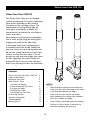
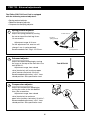
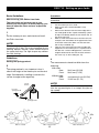
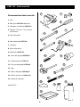
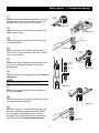
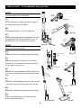
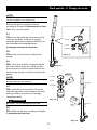
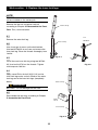
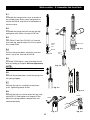
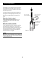
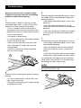
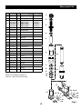
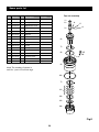
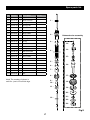
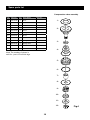
Front Fork RR 125cc
FGR 710
Owner’s Manual
FGR 710 - Safety Precautions
Note!
The front fork is a very important part of the
vehicle and will affect the stability.
Safety Symbols
In this manual, mounting instructions and
other technical documents, important
information concerning safety is
distinguished by the following symbols:
Read and make sure that you understand
the information in this manual and the mounting
instructions before you use this product. If you
have any questions regarding installation or
maintenance please contact an Öhlins dealer.
The Safety Alert Symbol means: Warning!
Your safety is involved.
Öhlins Racing AB can not be held
responsible for any damage to the front fork,
vehicle, other property or injury to persons, if
the instructions for installing and maintenance
are not followed exactly.
Warning!
The Warning Symbol means: Failure to
follow warning instructions can result in
severe or fatal injury to anyone working with,
inspecting or using the front fork, or
to bystanders.
Warning!
This product was developed and designed
exclusively for a specific vehicle model and
shall only be installed on the intended vehicle
model in its original condition as delivered from
the vehicle manufacturer.
Caution!
The Caution Symbol means: Special
precautions must be taken to avoid damage
to the front fork.
After installing this product, take a test ride
at low speed to make sure that your vehicle
has maintained its stability.
Note!
The Note Symbol indicates information that
is important regarding procedures.
If the suspension makes an abnormal noise,
or the function is irregular, or if you notice any
leakage from the product, please stop the
vehicle immediately and return the product to
an Öhlins Service Centre.
Note!
When working on this product, always consult
your Vehicle Service Manual.
This Manual shall be considered a part of
the product and shall therefore accompany the
product throughout its life cycle.
© Öhlins Racing AB. All rights reserved. Any
reprinting or unauthorized use without the written
permission of Öhlins Racing AB is prohibited.
Printed in Sweden.
Öhlins Front Fork FGR 710
Öhlins Front Fork FGR710
The Öhlins Front Forks use a Cartridge
system for damping. This gives a damping
force which depends on the speed of
the piston in the cartridge system. The
combination of spring and air-gap (oil
level) gives a possibility to adjust the
characteristics of the fork to suit different
tracks and riders.
For example a soft spring in combination
with a small air-gap (high oil level) gives a
progressive action of the front forks.
A telescopic front fork is depending on
a smooth friction free action. Make sure
your front forks are serviced regularly and
do not use strong solvents such as brake
cleaner to clean the front forks. This will
dry out the seal and steel tubes and cause
friction. Regularly, put some Öhlins red
grease (00146-01) on the steel tube and
work in by pushing the forks up and down.
Contents
Öhlins Front Fork RR 125cc FGR 710 External adjustments
Setting up your forks Work section - Tools 1. Change the Spring 2. Disassemble the Front Fork 3. Change the Seals 4. Replace the Tubes 5. Assemble the Front Fork Oil level adjustment Technical Information Troubleshooting Spare parts list
3
4
5
6
7
8
9
10
11
NOTE!
•
Read through the whole work section and
make sure that you understand all the steps
in the procedure before you begin.
12
13
14
15
•
Make sure that you have all the proper
tools needed for the section you are about
to work on, before you begin.
•
Clean all parts thoroughly after disassembly
•
Contact an Öhlins dealer if you have any
questions regarding the front fork.
FGR 710 - External adjustments
The Öhlins FGR 710 Front Fork is equipped
with the following external adjusters:
• Spring preload adjuster
• Rebound damping adjuster
• Compression damping adjuster
1
Spring preload adjuster
14 mm wrench
Adjust the spring preload by turning
the nut on top of the fork leg. Use a
14 mm wrench.
Increase
spring preload
Adjustment range: 0-18 mm.
On the adjustment nut, one turn will
change 1 mm in spring preload.
Recommended static sag is 15-25 mm.
2
Reduce
spring preload
Rebound adjuster
Adjust the rebound damping by turning
the screw at the top of the front fork. Use
tool 00794-01.
Adjustment range, from closed
valve (clockwise) until maximum open
valve (counter clockwise): 20 clicks.
Recommended adjustment “click”, from
closed position: See specification card.
3
Tool 00794-01
Compression adjuster
Adjust the compression damping by
turning the screw at the fork bottom.
Use a flat screwdriver.
Adjustment range, from closed
valve (clockwise) to maximum
open valve (counter clockwise): 20 clicks”.
Recommended adjustment “click”, from
closed position: See specification card.
FGR 710 - Setting up your forks
Basic Guidelines
Procedure
We recommend you to have an assistant for this
procedure.
How to set up your Öhlins front forks
The front forks are just one part of your
motorcycle and to get it to work properly, you
have to adjust the front and rear suspension
together.
1.
2.
3.
1
Put the motorcycle on a workstand and install
the Öhlins front fork.
4.
NOTE!
The lower triple clamp must not be tightened to
more than 12-15 Nm. This is also important for the
steering damper bracket, when located around
the upper front leg. Too high torque may deform
the front fork leg.
5.
Put the motorcycle on a stand.
Make sure that the shock absorber is fully
extended.
Measure the distance from the lower edge of the
rear mud guard or from a point marked by a piece
of tape, immediately above the rear wheel axle, to
the wheel axle. (R1)
Make a similar measurement on the front axle, for
example, from the bottom of the upper fork crown
to the front wheel axle. Make sure that the front
fork is fully extended. (F1)
Take the same measurements with the rider and
equipment on the motorcycle. It is important that
the rider has a correct riding posture, so that the
weight is balanced on the front and rear wheel in
the same way as when riding (R3, F3).
Guidelines
4
Setting the Spring preload
The measurements should not differ from the
following:
2
The spring preload is very important since it
affects the height of the motorcycle and the fork
angle. Consequently, handling characteristics
can be changed, even negatively.
14 mm
wrench
With rider:
Rear: Front: 30±5 mm (R1-R3)
30±5 mm (F1-F3)
Without rider:
Rear: Front: Just top out 0 mm (R1-R2)
15-25 mm (F1-F2)
NOTE!
An RR125 cannot afford to loose the momentum
that the sag would give in a straight line (loss of
top speed).
Increase
spring preload
Reduce
spring preload
F1
R1
F2
R2
Bike on a stand.
F3
R3
Bike on the ground.
Bike with rider on.
FGR 710 - Tools and oils
1
Recommended tools and oils
2
1. Vice
3
2. Soft jaws 00727-02 (one pair)
3. Hexagon screwdriver 00794-01
5
4. Wrench: 14 mm, 17 mm, 19 mm
and 24 mm.
4
5. Wire with hook
7
6. Seal head tool 01797-08
6
7. Heat gun
8. Brass wire brush
9. Sleeve pin 00797-01
8
10. Inner fork leg tool 00786-02
9
11. Attachment bar 01757-01
12. Pull-up spring tool 01765-03
11
10
13. Rag
14. Öhlins red grease 00146-01
15. Öhlins front fork oil 01311-01
12
16. Waste oil container
13
15
14
Loctite 2701
16
Work section - 1. Change the spring
1.1
14 mm
wrench
Release the spring preload completely by turning
the adjustment nut counter clockwise as far as
possible. Use a 14 mm wrench or socket.
Fig. 1.1
1.2
Loosen the screws that hold the fork legs in the
upper triple clamps.
Fig. 1.2
1.3
Tool
00797-01
Loosen the top nut assembly from the fork leg.
Use tool 00797-01.
1.4
Fig. 1.3
Remove the top nut assembly from the piston
shaft. Use a 14 mm wrench on the top nut and a
19 mm on the shaft.
14 mm
wrench
1.5
Remove the spring support and the spring. Use
a wire with a hook and carefully pull out the
preload tube.
Spring
support
19 mm
wrench
Spring
Fig. 1.4
1.6
Check the oil level according to Chapter Oil level
adjustment.
NOTE!
Use Öhlins Front fork oil 01311-01 only.
Fig. 1.5
1.7
Preload tube
Reinstall the preload tube, the new spring and
the spring support.
20 Nm
1.8
Reinstall the top nut assembly to the piston shaft
with tightening torque 20 Nm.
Fig. 1.8
1.9
Reinstall the top nut into the outer fork leg, with
the front wheel off the ground (use tool 0079701) and tighten with torque 10 Nm. Tighten
the upper triple clamps and adjust the preload
according to Chapter External adjustments.
Tool
00797-01
Fig. 1.9
Work section - 2. Dissasemble the front fork
NOTE!
This worksection can not be done while the forks
still are installed on the motorcycle.
14 mm
wrench
Fig. 2.3
2.1
Put the fork legs in upright position for about 5
minutes to allow the oil to settle.
Tool
00797-01
2.2
Fasten the fork leg in a vice with soft jaws.
Fig. 2.4
2.3
Release the spring preload completely by turning
the adjustment nut counter clockwise as far as
possible. Use a 14 mm wrench or a socket.
14 mm
wrench
Fig. 2.2
NOTE!
Do not use the preload adjuster to tighten or
loosen the top nut assembly.
19 mm
wrench
2.4
Spring support
Loosen the top nut assembly. Use tool 00797‑01.
Fig. 2.5
Spring
2.5
Remove the top nut assembly from the piston
shaft. Use a 14 mm wrench to the top nut and a
19 mm wrench to the shaft.
24 mm
wrench
Preload tube
2.6
Fig. 2.6
Remove the spring support and the spring. Use a
wire with a hook and carefully pull up the preload
tube.
Piston
rod unit
2.7
Use tool 01797-08 together with an 24mm wrench
to unscrew the piston rod unit from the fork leg.
Fork leg
2.8
Fig. 2.7
Use tool 01765-03 to remove the piston rod unit.
Washer
2.9
Drain all oil from the fork leg. Make sure that
washer 04729-02 falls out.
Fig. 2.8
Fig. 2.9
Work section - 3. Change the seals
NOTE!
This worksection can not be done while the forks
still are installed on the motorcycle.
Remove the top nut and piston rod unit
according to Chapter 2. Disassemble the Front
Fork. Then, continue below.
3.1
Remove the outer fork leg, clean the seal and
check the condition. If the seal is in good
condition apply some red grease (00146-01) to
the seal before reassembling the fork.
A damaged seal must be replaced!
1) Circlip
2) Seal
3) Washer
3.2
Remove the circlip, the seal and finally the
washer.
Tire lever or
equivalent
Fig. 3.2
3.3
Apply a thin layer of Öhlins red grease (0014601) to the washer and to the sealing surfaces
of the fork seal. Install the washer and the seal
into the outer fork leg. Install the circlip into the
groove.
Fig. 3.1
NOTE!
3) Circlip
NOTE!
It is important to use the correct grease in order to
achieve optimum fork function.
2) Seal
3.4
1) Washer
Re
dg
rea
se
Outer fork
leg
Apply some Öhlins fork oil (01311-01) on the
inner fork legs outer surface. Slide on the outer
fork legs carefully on to the inner fork legs
(completely down).
Fig. 3.3
WARNING!
Be careful - Do not damage the fork seal!
Öhlins
fork oil
3.5
Reassemble the fork legs according to Chapter
5. Assemble the Front fork.
Fig. 3.4
Inner fork
leg
Work section - 4. Replace the inner fork legs
NOTE!
This worksection can not be done while the forks
still are installed on the motorcycle.
Remove the top nut and piston rod unit
according to Chapter 2. Disassemble the Front
Fork. Then, continue below.
Outer fork leg
4.1
Tool
Remove the outer fork leg.
Inner fork leg
4.2
00786-02
Use a heat gun to warm up the fork bottom.
Use tool 00786-02 to unscrew and remove the
inner fork leg. Clean the threads thoroughly from
Loctite.
Fig. 4.1
4.3
Install the new inner fork leg using tool 0078602. Use Loctite 2701 on the threads. Tighten
with torque to 160 Nm.
Fig. 4.2
4.4
Apply some Öhlins fork oil (01311-01) on the
inner fork legs outer surface. Slide on the outer
fork legs on to the inner fork legs (completely
down).
Outer fork leg
WARNING!
Be careful - Do not damage the fork seal!
4.5
Reassemble the fork legs according to Chapter
5. Assemble the Front Fork.
Öhlins
fork oil
Inner fork leg
Fig. 4.4
10
Work section - 5. Assemble the front fork
5.1
Assemble the compression valve assembly to
the cylinder tube. Smear some red grease on
washer 04729-02 and stick it to the bottom of
the base valve.
5.2
20 Nm
Assemble the piston rod unit into the fork leg
and tighten with 20Nm. Use tool 01797-08.
5.3
Pour Öhlins Front Fork Oil 01311-01 into the
inner fork leg, approximately 20-25 mm above
the cylinder tube.
Compr.
valve
assy
5.4
20-25 mm
Fig. 5.3
Washer
Pull the rod up and down and make sure that
there is no air left. Use tool 01765-03.
Piston
rod
Fig. 5.1
5.5
Push tool 01765-03 to a stop and check the oil
level according to Chapter Oil level adjustment.
Fig. 5.2
NOTE!
Use Öhlins Front Fork oil 01311-01 only!
5.6
Reinstall the preload tube. Install the spring and
the spring support.
5.7
Reinstall the top nut assembly to the piston
shaft. Tightening torque 20 Nm.
Fig. 5.5
Fig. 5.6
5.8
Reinstall the top nut into the outer fork leg. Use
tool 00797-01 and tighten with torque 10 Nm.
Adjust the spring preload, compression and
rebound damping.
10 Nm
20 Nm
Tool
00797-01
Fig. 5.7
11
Fig. 5.8
Oil level adjustment
Compared with conventional type of front forks,
the upside down front forks are very sensitive
to variations in oil level. Therefore, adjust the oil
level with special care.
A change in the fork oil level will not affect the
spring force at the beginning of the fork travel,
but will have a great effect at the end of the
travel.
Push to a stop,
use tool 01765-03
Öhlins Front Fork
fluid 01311-01
When the oil level is raised:
The air spring in the later half stage of travel
is stronger, and make the front forks more
progressive.
The edge of the
outer fork leg
When the oil level is lowered:
Check the
oil level
The air spring of the travel is reduced, and thus
the front fork less progressive. The oil level
works most efficient at the end of the fork travel.
Air spring characteristics shown, is a general
card description to understand the difference
when the oil level is changed.
Fig. 5.4
NOTE!
Adjust the oil level according to the figure with
the fork leg fully compressed (with springs and
preload tube taken out). For the correct oil level
- see specification card.
12
Technical information
Front Fork length 615 mm
Stroke 100 mm
Free spring length 260 mm
Recommended settings
Torque
Compression: 10 clicks
Lower triple clamp bolt 12-15 Nm
Upper triple clamp bolt 18-22 Nm
Rebound: 12 clicks
Grease
Spring preload: 4 turns from fully compressed
position
Öhlins Front Fork
Red Grease 00146-01
Preload range: 0-15 mm (0-15 turns)
Spring rate
21610-55 5.5 N/mm
Service intervals
Optional springs available
This product is designed for racing use
only.
21610-50
21610-60
21610-65
21610-70
5.0 N/mm
6.0 N/mm
6.5 N/mm
7.0 N/mm
Recommended service every 10 hours.
Disposal
Oil capacity
Discarded products should be handed over
to an authorized Öhlins Service Centre for
proper disposal.
See specification card.
Use Öhlins high performance front fork
oil no. 4 (01311-01) only.
13
Troubleshooting
3
Below you will find a few examples of how
to adjust for the most common road holding
problems in Road Racing driving.
The front end feels unpredictable and un-safe in
the middle of the corner (between braking and
getting on power).
1
• Not enough rebound damping. Put on more
damping.
The front wheel “chatters” entering a corner,
the problem goes away, as soon as you let the
brakes off, or when you get on the power.
• Too much rebound damping. If it at the
same time feels harsh, take off some rebound
damping.
• This is caused by the fact that the fork is
working too low in the travel and reaches the
progressive, hard part at the end of the travel.
• Too much compression damping. Also gives
a harsh feeling. Take off some compression
damping.
• Put on more preload.
• Change to a harder spring.
4
• If a lot of stroke remains after riding, drop the
oil level. See oil level chart.
The front end loses grip coming out of a corner.
• Make sure the front forks have no friction.
• Not enough rebound damping. Put on some
more rebound damping.
• Rear ride height is to high, too much rear
spring preload.
• Too much preload. Take off some preload.
• Lower the rear end by taking off preload
from rear shock spring.
• Rear end is too soft. Put on a harder rear
spring.
• Front end is too high. Lower the front end by
pulling the fork legs through the triple clamps.
1
As mentioned in the beginning, the whole bike
setup affects the front forks. Try to understand
the feelings and work step by step.
NOTE!
We advise to change only one thing at a time and
do everything step by step.
2
4
The front wheel is jumping during the last part of
braking.
• If a lot of stroke remains, the oil level is too
high. Lower the oil level.
• If the fork is bottoming, put in harder springs
and keep the oil level.
14
Spare parts list
Pos
Part No.
1-1
-
Pcs Description
-
Top nut assembly
Remarks
1-2
03316-01
2
Spring support
1-3
21610-55
21610-50
21610-60
21610-65
21610-70
2
2
2
2
2
Spring
Option spring
Option spring
Option spring
Option spring
1-4
21611-01
2
Guide ring
1-5
01460-50
2
Preload tube
1-6
01550-03
2
Fork leg outer
1-7
01683-03
2
Bushing
1-8
01684-03
2
Bushing
1-9
02463-01
2
Washer
1-10
02461-01
2
Seal MX
1-11
02465-01
2
Circlip
1-12
21606-01
2
Cylinder tube
1-13
02469-03
2
Fork leg inner
1-14
01902-17
1
Fork bottom LH
Left
1-15
01902-18
1
Fork bottom RH
Right
1-16
01046-02
4
Screw
1-17
01669-01
2
Sleeve
1-18
01473-02
2
Circlip
1-19
00338-53
2
O-ring
1-20
01242-03
2
Adjustment needle
7-
1-21
01474-01
2
Spring
8-
1-22
00884-02
4
Ball
See page 16
12-
4.0/163/5.5
4.0/158/5.0
4.2/154/6.0
4.2/157/6.5
4.4/148/7.0
3-
45-
612 -
13 -
910 -
Note! The number of pieces is
valid for 1 pair of Front fork legs
11 17
17
14
15
20 22
21
22
20 22
21
22
16
15
19
18
16
19
18
Fig.1
Spare parts list
Pos
Part No.
Pcs Description
2-1
01473-01
2
Circlip
2-2
00577-01
2
O-ring
2-3
01467-02
2
Adjustment screw
2-4
00884-04
4
Ball
2-5
01474-01
2
Spring
2-6
03312-01
2
Adjuster
2-7
03309-01
4
Shim
2-8
00338-72
2
O-ring
2-9
03318-09
2
Adjustment housing
2-10
00338-92
2
O-ring
2-11
03317-01
6
Spring
2-12
03309-02
2
Shim
2-13
03313-01
2
Nut
2-14
03315-01
2
Preload socket
2-15
00382-06
2
Screw
2-16
00338-56
2
O-ring
Top nut assembly
Remarks
123-
4
5
4
t=0,1mm
6-
7t=0,38mm
8-
15
16
9Note! The number of pieces is
valid for 1 pair of Front fork legs
10 7-
11 12 13 14 -
Fig.2
16
Spare parts list
Pos
Part No.
3-1
02366-16
Pcs Description
2
Adjustment rod
3-2
03314-12
2
Shaft extension
3-3
00338-76
2
O-ring
3-4
02302-10
2
Spring guide
3-5
01582-12
4
Spacer
3-6
01582-10
2
Spacer
3-7
01580-01
2
Bump rubber
3-8
21607-01
2
Tube top cap
3-9
00110-01
2
Bushing
3-10
00438-28
2
O-ring
3-11
01582-12
4
Spacer
3-12
02367-09
2
Shaft
3-13
00438-31
2
O-ring
3-14
01698-10
2
Rebound needle
3-15
02322-01
2
Spring
3-16
01654-11
2
Piston holder
3-17
-
-
Shim stack
3-18
02061-03
2
Piston, rebound
3-19
01447-02
2
Piston ring
3-20
-
-
Shim stack
See spec. card
See spec. card
3-21
-
-
Washer
3-22
00153-01
2
Washer
3-23
01675-01
2
Nut
Remarks
1-
2-
Rebound valve assembly
313 -
4-
14 -
15 See spec. card
5-
Note! The number of pieces is
valid for 1 pair of Front fork legs
6-
16 -
78-
17 -
910 -
18 -
11 -
19 20 -
12 -
21 22 23 -
Fig.3
17
Spare parts list
Compression valve assembly
Pos
Part No.
4-1
00520-26
Pcs Description
2
Shim
Remarks
4-2
21609-01
2
Base valve
4-3
-
-
Washer
See spec. card
4-4
-
-
Shim stack
See spec. card
4-5
01670-04
2
Piston
4-6
00438-02
2
O-ring
4-7
01669-01
2
Sleeve
4-8
00530-22
2
Shim
4-9
01671-02
2
Spring
4-10
01672-01
2
Spring collar
4-11
00120-01
2
Washer
4-12
01675-01
2
Nut
1-
2-
3-
4-
Note! The number of pieces is
valid for 1 pair of Front fork legs
5-
6-
78-
9-
10 11 12 -
18
Fig.4
www.ohlins.com
Öhlins Owner’s Manual FGR 710| Part No. 07280-14_3 | Issued 2009-02-16 | © 2009 Öhlins Racing AB
Your Öhlins retailer:
Öhlins Racing AB
Box 722
SE-194 27, Upplands Väsby
Sweden
Phone: +46 (0)8 590 025 00
Fax: +46 (0)8 590 025 80
www.ohlins.com