1
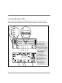
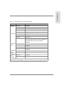
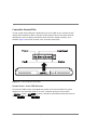
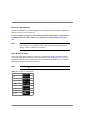
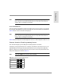
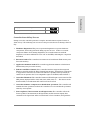
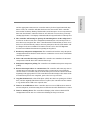
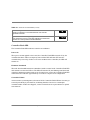
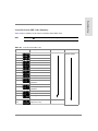
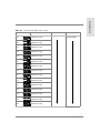
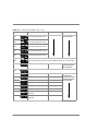
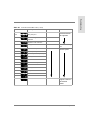
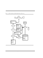
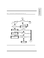
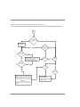
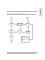
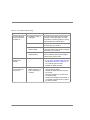
Troubleshooting
Controller Enclosure Troubleshooting
Introduction
This chapter discusses how to identify interface problems, how to identify a controller
failure, and how to service the controller modules and the memory modules within the
controller enclosure as shown in Figure 92. For troubleshooting procedures, refer to the
"Master Troubleshooting Table" on page 565
Figure 92 Controller Modules in Controller Enclosure
Controller Enclosure Troubleshooting
505
Controller Enclosure LEDs
Figure 93 shows the locations of the status LEDs for the controller enclosure. Table 61
summarizes the operating LED states for all components within the controller enclosure.
A
B
C
D
E
F
G
H
I
J
K
L
M
N
O
P
Q
Figure 93 Controller Enclosure LEDs
506
Controller Enclosure Troubleshooting
Power On LED
Power Fault LED
Fan Fault LED
Controller Fault LED
Fast Write Cache LED
Controller Power LED
Controller Fault LED
Heartbeat LED
Status LEDs
Fault B LED
Full Charge B LED
Fault A LED
Full Charge A LED
Power 1 LED
Power 2 LED
Fan Power LED
Fan Fault LED
Troubleshooting
Table 61 Normal LED Status for Controller Enclosure
Module
LED
Normal State
Controller
Enclosure
Power On
On (green)
Power Fault
Off
Fan Fault
Off
Controller Fault
Off
Fast Write Cache
On (green) while data is in cache
Controller Power
On (green)
Controller Fault
Off
Heartbeat
Blink (green)
Status
Green
There are 8 status LEDs. The number and pattern of
these LEDs depend on how your system is
configured.
Fault - B
Off
Full Charge - B
On (green)1
Fault - A
Off
Full Charge - A
On (green)1
Controller
Power
Assembly
Power 1
On (green)
Power 2
On (green)
Controller
Fan
Assembly
Fan Power
On (green)
Fan Fault
Off
Controller
Controller
Battery
1. Both Full Charge A and Full Charge B LEDs are ON after batteries are fully charged.
The LEDs flash while charging is in progress, and remain on when charging is complete.
Controller Enclosure Troubleshooting
507
Controller Status LEDs
A bank of eight status LEDs plus a Fault LED and a Power LED on the controller module
display status information. Each controller module displays only its own status and fault
information; it does not display information about the other controller module, if it is
installed. Figure 94 shows the location of the controller status LEDs.
.
Figure 94 Controller Module Status LEDs
Normal Active -Active LED Patterns
The Heartbeat LED is in the most-significant position of the 8 status LEDs. The pattern
displayed on the Status LED bank for an active controller alternates between 0x00
to 0x80
. A passive controller’s status LEDs will alternate between
0x6E
to 0xEE
.
508
Controller Enclosure Troubleshooting
Troubleshooting
Errors During Normal Operations
It is possible for the controller to encounter errors from which it is unable to recover
during normal operations. Specific status LED patterns are used to give a visual indication
of any problem. The error pattern returns to the normal setting after the problem has been
fixed. These error patterns are listed in Table 66 on page 519.
If the controller encounters an unexpected processor exception, the error pattern of 0xE1
will briefly be displayed before the controller reboots itself.
Note
Note that a l indicates the LED is ON or Flashing.
If the controller encounters a PCI bus fault while running, the error pattern of 0xAA will be
displayed solid ON the LED bank
.
Controller Hardware Reset Pattern
Whenever the controller is held in a hardware reset state, all LEDs are on. Therefore, the
pattern displayed by the LEDs is 0xFF
.
Hardware Diagnostics Errors
Hardware diagnostics are run during power ON or when a controller module is reset. As
diagnostics are run, the LEDs display information indicating which diagnostics are running.
The patterns displayed by the LEDs correspond to the Component Code of the component
being tested.
Note that the codes are 16-bit and the LEDs display the most significant byte first, followed
by the least significant byte. The displays cycle approximately once every 2 seconds.
If a fatal diagnostic error occurs, the controller will not boot, and the LEDs will
continue to display a code that gives an indication of the failed component. See
Table 66 on page 519 for these codes.
Controller Enclosure Troubleshooting
509
Hardware Initialization
Hardware initialization codes are displayed on the LED bank as the hardware is initialized
during a power up or reset sequence.
If the controller encounters errors during hardware initialization, error patterns
are displayed on the LEDs. These error patterns are listed in Table 66 on page
519.
These status codes are displayed only momentarily and are typically not visible
if the controller is operating normally. They are only visible if the firmware
“hangs” while executing these functions.
Note
Boot Menu Execution
Prior to the Boot Menu actually executing, the controller will display a number of status
codes indicating various functions being executed (see Table 66 on page 519). Once the
Boot Menu is invoked, the controller will cycle through all of the LEDs one by one, and the
LED pattern displayed is shown in Table 62.
Note that a l indicates the LED is ON or Flashing.
Note
Table 62 LEDs Prior to Boot Menu
0x01
0x02
0x04
0x08
0x10
0x20
0x40
0x80
x01, etc.
510
Controller Enclosure Troubleshooting
Kernel
Troubleshooting
Note
These status codes are displayed only momentarily and are typically not visible
if the controller is operating normally. They are only visible if the firmware
“hangs” while executing these functions.
Initialization
After the hardware is initialized, and the Boot Menu has been given a chance to be invoked,
the controller will initialize the kernel as the final part of the Boot Firmware initialization.
Table 66 lists the status codes that are displayed.
Note
These status codes are displayed only momentarily and are typically not visible
if the controller is operating normally. They are only visible if the firmware
“hangs” while executing these functions.
Table 66 lists the LED patterns while diagnostics are run, or when diagnostic failures occur.
Firmware Download / Flash Programming Patterns
The controller displays specific LED patterns during firmware download.
If firmware is being downloaded to the controller, the LEDs are all turned ON one by one,
until all LEDs are on. They are then all turned OFF one by one. The speed at which the
LEDs are turned ON or OFF depends on the rate at which code is being downloaded. The
LED pattern displayed is shown in Table 63.
Note
Note that a l indicates the LED is On or Flashing.
Table 63 Firmware Download LED Patterns
0x01
0x03
0x07
0x0F
0x1F
Controller Enclosure Troubleshooting
511
0x3F
0x7F
0xFF
0x7F
0x3F
0x1F
0x0F
0x07
0x03
0x01
0x03, etc...
LED patterns are also displayed when the controller programs Flash EEPROM with
downloaded code. See Table 64. Different patterns are displayed when the download
occurs. These LED patterns are also displayed during automatic code synchronization.
Note that a l indicates the LED is On or Flashing.
Note
Table 64 EEPROM LEDs
Description
LED Pattern
In-between programming steps
0x80
Erasing boot flash segments
0x81
Writing boot flash segments
0x82
Verifying erase of boot segments
0x83
Verifying write of boot segments
0x84
Erasing file flash segments
0x89
Writing file flash segments
0x8A
512
Controller Enclosure Troubleshooting
0x8B
Verifying write of file flash segments
0x8C
Troubleshooting
Verifying erase of file flash segments
Controller Start-Of-Day Process
During a reset the controller performs a complete internal selftest sequence known as
“Start Of Day”. The following is an overview of the processes that occur during a Start-OfDay.
1.
Hardware diagnostics: This process performs diagnostics on specific hardware
components, and is only performed during a power-on reset. If there is a critical
component failure when running diagnostics, the controller firmware will halt
diagnostics execution and flash an error code on the LEDs, indicating the component
that failed.
2.
Bootware loaded: The controller’s boot firmware is loaded from Flash memory into
Processor memory.
3.
Application firmware loaded: The controller application firmware is loaded from
Flash memory into processor memory.
4.
Ethernet and Fibre Channel: If the controller hardware supports the integrated
Ethernet controller and/or the Fibre Channel host interface, the firmware components
to support these interfaces are loaded. The Ethernet capability must specifically be
enabled via an option in the User-configurable region of NVSRAM, offset 0x28 bit 3.
5.
Controller Heartbeat: The controller heartbeat LED will begin to turn on and off. The
LED pattern displayed will be 0x00, 0x80, 0x00, 0x80, 0x00, etc.… The absence of the
heartbeat LED, is an indication that a fatal error has occurred.
6.
Controller firmware components to handle host operations: The controller will
initialize the host operations to allow the controller to receive and handle operations
issued by a host system.
7.
Power-up/Reset Unit Attention for all logical units: The controller will set the
Power-up/Reset Unit Attention for all logical units, and the first non-inquiry host
command to the logical unit will be returned with a Check Condition, along with the
Controller Enclosure Troubleshooting
513
sense data indicating that a power-on or reset has occurred. The Sense Key, ASC, and
ASCQ will be 0x06, 0x29, and 0x00 respectively.
8.
Mode Select Commands disabled: The controller will now disable Mode Select
Commands until the Start-Of-Day process is complete. This is required so that
subsystem configuration changes are prohibited until the controller has finished
booting. Mode Select commands issued by a host during this time period, will be
returned with an error by the controller, indicating that the addressed logical unit is
currently not ready, and is in the process of becoming ready.
9.
Host Side selection enabled: The controller will now enable selection on the host
side, allowing host to select the controller. On a bus reset, this step is completed within
250ms of receiving the bus reset. On power-up, this step is completed within 10 seconds.
10. Respond to host’s Inquiry commands: The controller is now able to respond to host
Inquiry commands, based on the knowledge of previously-existing logical units, as well
as their ownership information. An Inquiry issued by a host to a logical unit, will return
information indicating whether the logical unit exists, and if it is owned by this
controller. If the controller receives a non-Inquiry command, it delays the command a
period of time determined by the value set in NVSRAM, before returning a “Not Ready
– logical unit is in process of coming ready” error.
11. Drive operations initialized: The controller will now initialize firmware components
to handle drive operations, allowing the controller to issue commands to the drives.
12. LUN ownership read: The controller will read LUN ownership from the NVSRAM.
13. Loaded firmware modules displayed: The controller will display a list of loaded
firmware modules on the serial port.
14. Spin up of drives: The controller reads NVSRAM information for previously existing
drives, and spins up the drives, following the Drive Spin-up algorithm as defined in
NVSRAM. If the Drive-Spin-up algorithm defined in the NVSRAM, requires the controller
to wait for a Start-Unit command from the host before spinning up the drives, the StartOf-Day process will be suspended at this time, until the host issues a Start Unit
command.
15. Read drive and LUN configuration information from dacStore. The controller will
now read the drive and LUN configuration information from the dacStore on the drives,
514
Controller Enclosure Troubleshooting
Troubleshooting
and the appropriate structures are created in memory. If these logical units had dirty
data in cache, the controller will flush the data to the drive media. If the controller
believes that it’s Battery Backup Unit has failed, it will attempt to recover any mirrored
data from the alternate controller. Hosts are now allowed access to these previouslyexisting logical units. Non-Inquiry commands will no longer fail with a Not Ready error.
16. The controller will attempt to spin up all remaining drives in the subsystem. If
new drives are discovered, their configuration information is read, and any LUNs on
these drives are brought on line. If the controller finds LUN information on these “new”
drives for a LUN that already exists in the array subsystem, then the LUN number will
be changed to the next available LUN number. Please refer to the LUN Migration
document for additional information regarding moving drives.
17. Read array subsystem configuration: The controller will read the array subsystem
configuration from the dacStore on the drives to confirm the correct mode of redundant
controller operation.
18. Drive and controller hot-swap enable: The controller now initializes the firmware
components to handle drive and controller hot-swaps.
19. Subsystem component polling: The controller now initializes subsystem component
polling.
20. Restart interrupted drive re-constructions: The controller will restart any drive reconstruction processes that were interrupted due to power-fail or resets. With the
current release of controller FW, the reconstruction process will be restarted from the
beginning of the appropriate LUN. The controller has no knowledge of how much of the
reconstruction process was completed, prior to the reset or power-fail.
21. Copy-Back initiated: If a Global Hot Spare (GHS) drive has been sparing for a Failed
drive, and the originally Failed drive has been replaced, the controller will now initiate
a copy-back from the GHS to the replaced drive.
22. Discover new GHS drives: If the controller discovers a new GHS has been inserted
into the subsystem, it will start using the new GHS drive should a Failed drive be found.
23. Discover missing drives: The controller will display a list of drives that had LUN
configuration on them but were cold-removed during the last power-down.
Controller Enclosure Troubleshooting
515
24. Spin down Failed Drives: Drives that are marked Failed, are now spun down, and
their Fault LEDs are lighted.
25. Restart LUN binding: The controller will discover and restart LUNs that were in the
process of being bound when the reset or power fail occurred.
26. LUN 0 created: If no LUNs are discovered, a default LUN is created.
27. Enable Mode Select commands: The controller will now enable Mode Select
commands, allowing users to make configuration changes, such as adding or deleting
LUNs, changing controller modes, or drive states.
28. Controller Start-Of-Day completed.
516
Controller Enclosure Troubleshooting
Troubleshooting
Errors During / After Firmware Download
Different patterns are displayed after downloading firmware. The patterns are shown in
Table 65.
Note
Note that a l indicates the LED is On or Flashing.
.
Table 65 Firmware Download LEDs
Error
LED Pattern
Download file is lacking header record.
0x61
Download file header fails checksum test.
0x64
Download file header contains unexpected download type.
0x65
The user should attempt to download a known good file.
0x67
Intermodule error call to flash function passed bad flash type. There is
a mismatch between the Boot Firmware and the Application Firmware.
The user must download matched versions of both controller
Bootware and controller Application Firmware.
0x91
Invalid address in flash device.
0x92
Unable to fully erase boot flash segments (bad voltage or device).
Replace the controller board.
0x95
Unable to fully erase file flash segments (bad voltage or device).
Replace the controller board.
0x96
Unable to program boot flash after 3 cycles of erase and write.
Replace the controller board.
0x97
Unable to program application file flash after 3 cycles of erase and
write. Replace the controller board.
0x98
Software load failure. There is a mismatch between the Boot Firmware
and the Application Firmware. The user must download matched
versions of both code types.
0xE6
Controller Enclosure Troubleshooting
517
Table 65 Firmware Download LEDs (cont’d)
Kernel missing, or kernel CRC mismatch. The user must download a
matching combination of controller Bootware and controller
Application Firmware.
0xE7
Application Firmware missing, or Application CRC mismatch. The user
must download a version of controller Application Firmware that
matches the currently loaded controller Bootware.
0xE8
Controller Fault LED
The Controller Fault LED indicates a number of conditions.
Power On
When power is first applied to the board, the Controller Fault LED is turned ON by the
controller hardware. This is a temporary state and the LED will turn OFF after the
controller has powered up. If there is an error condition in the controller, the LED will
remain On.
Firmware Download
When the downloadable firmware is initialized, it takes control of the Controller Fault LED
and continues to drive the LED on. The LED will remain ON (not blinking) until the board
completes diagnostics with no fatal errors. If a fatal error occurs, the Controller Fault LED
will remain on. It will take approximately 6 seconds to complete level 0 diagnostics.
Controller Failure
A timeout timer (watchdog timer) also turns ON the Controller Fault LED if it does not get
serviced periodically by the firmware, indicating that there has been a catastrophic
controller failure. If this error happens, contact a trained service representative to upload
new firmware.
518
Controller Enclosure Troubleshooting
Troubleshooting
Controller Status LED Codes Summary
Table 66 lists a summary of the various controller Status LED codes.
Note
Note that a l indicates the LED is On or Flashing.
Table 66 Controller Status LEDs codes
Code
Description
Comments
Cause / Solution
0x20
Kernel Start
Kernel Init. status
0x21
Kernel cache initialization
Controller module /
reseat or replace
0x22
Kernel IDT set-up
0x23
Kernel hardware initialization
0x24
Kernel initialization
0x25
Kernel Task Manager start-up
0x26
Kernel memory initialization
0x27
Kernel clock start
0x28
Kernel service initialization
0x29
Kernel symbol table initialization
0x2A
Kernel network initialization
0x2B
Kernel flash EEPROM file system
initialization
0x2C
Kernel NMI enabled
0x2D
Kernel page management
initialization
0x2E
Kernel shell initialization
0x2F
Kernel application load
0x30
Kernel application start
0x33
0x00
Non-volatile Memory (8 Kbytes)
diagnostics running
HW Diag. status
Controller Enclosure Troubleshooting
519
Table 66 Controller Status LEDs codes (cont’d)
Code
Description
Comments
Cause / Solution
0x36
0x00
Processor DRAM diagnostics
running
HW Diag. status
Controller module /
reseat or replace
0x37
0x00
RPA DRAM diagnostics running
0x38
0x00
Processor Level 2 Cache
diagnostics running
0x44
0x01
CDC diagnostics running
0x44
0x02
SIO diagnostics running
0x44
0x03
RPA diagnostics running
0x44
0x12
SIO Interrupt diagnostics running
0x54
0x00
ICON diagnostics running
0x55
0x00
FReD diagnostics running
0x61
Download file is lacking header
record
0x64
Download file header fails
checksum test
0x65
Download file header contains
unexpected download type
0x65
0x00
Host SCSI Channel (53C825)
diagnostics running
0x65
0x10
Host SCSI Channel (53C875)
diagnostics running
0x65
0x20
Host Fibre Channel Interface
diagnostics running
0x67
CRC failure on downloaded data
520
Controller Enclosure Troubleshooting
Firmware file is bad /
Download Firmware
with a good file.
Controller module /
reseat or replace
Troubleshooting
Table 66 Controller Status LEDs codes (cont’d)
Code
Description
Comments
Cause / Solution
0x6B
0x01
Drive SCSI Channel 1 (53C810)
diagnostics running
HW Diag. status
Controller module /
reseat or replace
0x6B
0x02
Drive SC SI Channel 2 (53C810)
diagnostics running
0x6B
0x03
Drive SCSI Channel 3 (53C810)
diagnostics running
0x6B
0x04
Drive SCSI Channel 4 (53C810)
diagnostics running
0x6B
0x05
Drive SCSI Channel 5 (53C810)
diagnostics running
0x6B
0x11
Drive SCSI Channel 1 (53C825)
diagnostics running
0x6B
0x12
Drive SCSI Channel 2 (53C825)
diagnostics running
0x6B
0x13
Drive SCSI Channel 3 (53C825)
diagnostics running
0x6B
0x14
Drive SCSI Channel 4 (53C825)
diagnostics running
0x6B
0x15
Drive SCSI Channel 5 (53C825)
diagnostics running
0x6B
0x21
Drive SCSI Channel 1 (53C875)
diagnostics running
0x6B
0x22
Drive SCSI Channel 2 (53C875)
diagnostics running
0x6B
0x23
Drive SCSI Channel 3 (53C875)
diagnostics running
0x6B
0x24
Drive SCSI Channel 4 (53C875)
diagnostics running
0x6B
0x25
Drive SCSI Channel 5 (53C875)
diagnostics running
Controller Enclosure Troubleshooting
521
Table 66 Controller Status LEDs codes (cont’d)
Code
Description
Comments
Cause / Solution
0x6C
0x01
Drive SCSI Channel 1
Turnaround diagnostics running
HW Diag. status
Controller module /
reseat or replace
0x6C
0x02
Drive SCSI Channel 2
Turnaround diagnostics running
0x6C
0x03
Drive SCSI Channel 3
Turnaround diagnostics running
0x6C
0x04
Drive SCSI Channel 4
Turnaround diagnostics running
0x6C
0x05
Drive SCSI Channel 5
Turnaround diagnostics running
0x6E
0xEE
Passive controller - Normal during Firmware download. The controller may be in this
state after power ON (in this case, use the AM60 software to set to “Active” state).
0x80
In-between programming steps
0x80
0x00
Active controller - Normal State
0x81
Erasing boot flash segments
0x82
Writing boot flash segments
0x83
Verifying erase of boot segments
0x84
Verifying write of boot segments
0x89
Erasing file flash segments
0x8A
Writing file flash segments
0x8B
Verifying erase of file flash
segments
0x8C
Verifying write of file flash
segments
522
Controller Enclosure Troubleshooting
Firmware file is bad /
Download Firmware
with a good file.
Firmware file is
downloading or
Firmware file is bad /
Download Firmware
with a good file.
Troubleshooting
Table 66 Controller Status LEDs codes (cont’d)
Code
Description
Comments
Cause / Solution
0x91
Intermodule error call to flash
function passed bad flash type
Firmware file is bad / Download Firmware
with a good file. Attempt to download Firmware
again. If the problem persists, replace the
controller module.
0x92
Invalid address in flash device
0x93
Length too long for flash device
Firmware file is bad / Download Firmware
with a good file. Attempt to download Firmware
again. If the problem persists, replace the
controller module.
0x95
Unable to fully erase boot flash
segments
0x96
Unable to fully erase file flash
segments
0x97
Unable to program boot flash
after 3 cycles of erase and write
0x98
Unable to program application file
flash after 3 cycles of erase and
write
0xA1
Start Boot Firmware
0xA2
Initialize core hardware
0xA3
Determine hardware configuration
0xA4
Determine CDC memory size
0xA5
Determine RAID Parity Assist
memory size
0xA6
Initialize BIOS timer
0xA7
Initialize serial interface
0xA8
General software initialization
0xA9
Display Boot banner
0xAA
Test Boot Menu invocation
0xAA
(steady)
PCI fatal fault
0xAB
Test Boot Menu memory
Controller module /
reseat or replace
Boot Funct. Status
Boot Funct. Status
Memory problem /
reseat or replace
Controller Enclosure Troubleshooting
523
Table 66 Controller Status LEDs codes (cont’d)
Code
Description
Comments
Cause / Solution
0xAC
Load Boot Menu
Boot Funct. Status
Controller module /
reseat or replace
0xAD
Invoke Boot Menu
0xAE
Exit Boot Menu
0xAF
Test Diagnostics Manager
memory
Memory problem /
reseat or replace
0xB0
Load Diagnostics Manager
Controller module /
reseat or replace
0xB1
Invoke Diagnostics Manager
Controller module /
reseat or replace
0xB2
Clear work memory
Memory problem
0xB3
Clear extended memory
0xB4
Kernel set-up
Controller module /
reseat or replace
0xB5
Enable Level 2 cache
0xB6
Load kernel
0xB7
Load network manager
0xB8
Load Application code symbol
table
0xB9
Invoke kernel
0xBE
Unexpected return from kernel
0xBF
Rebooting after Boot Firmware
download
0xE3
No host channel devices on the
PCI bus
0xE4
Wrong number of drive channel
devices on the PCI bus
0xE5
No RPA device on the PCI bus
524
Controller Enclosure Troubleshooting
HW Init. status
Troubleshooting
Table 66 Controller Status LEDs codes (cont’d)
Code
Description
0xE6
Software load failure
0x66
RPA parity error
0xE7
Kernel missing, or kernel CRC
mismatch
0xE8
Application Firmware missing, or
Application CRC mismatch
0xEA
Swapped controller
0xF1
Processor set-up
0xF2
CDC chip set-up
0xF3
RAID Parity Assist chip set-up
0xF4
Memory Test
0xF5
Load Boot Firmware
0xF7
Clear Boot memory
0xF8
Enable Protected mode
0xF9
Memory test failure
0xFA
Exception error
0xFB
Start mode determination
0xFC
Invoke Boot Firmware
0xFF
Hardware reset
Comments
Cause / Solution
Firmware file is bad /
Download Firmware
with a good file.
Controller is in wrong
slot.
HW Init. status
Controller module /
reseat or replace
Hardware reset is in
progress or there is a
bad controller
module.
Controller Enclosure Troubleshooting
525
Identifying Interface Problems
Types of Interface Problems
Interface problems include any malfunctions that delay, interrupt, or prevent successful
input/output (I/O) activity between the hosts and other devices. This includes
transmissions between the controller enclosure and disk enclosures attached to it. For the
purpose of this discussion, the controller enclosure’s interface components include the
following:
•
Internal components
– Two Fibre Channel controller modules
– Controller enclosure card cage (includes midplane w/SCSI connectors)
•
External components:
– Fibre Channel host adapters, cables, and hub or switching devices
– SCSI cables, terminators, BCC modules in the disk enclosure
Interface problems can be caused by either software or hardware.
•
Software problems, which indicate operating system or disk array application errors,
typically involve one or more of the following:
– Host operating system software error
– Disk array or other application error
– Incorrect configuration settings
•
Hardware problems, which indicate defective equipment, include the following:
– Loose, disconnected, or damaged interface cables or connectors
– Improper SCSI termination on disk enclosure bus or defective terminators
– Improper interface ID settings (hardware switches)
– Failed controller modules, memory modules, or controller enclosure midplane
– Failed disk modules, host adapter boards, or other devices on the Fibre Channel
network
– Failed disk modules
526
Controller Enclosure Troubleshooting
Troubleshooting
Hints for Troubleshooting Interface Problems
The first step in troubleshooting interface problems is determining whether the problem is
caused by hardware or software. The following information should aid in making this
determination:
•
If the problem occurred during or immediately following a software activity, try to undo
whatever the software did, then step through each software function (in smaller
increments) until the problem occurs again. This will identify the function that is
working incorrectly.
•
If the problem occurred without an apparent software-related activity, check the
operating system and storage management software for error messages and associated
procedures. This may help determine if it is a software or hardware problem.
•
Check the controller modules for faults.
•
Check all the interface cables, particularly the host Fibre Channel cables, to make sure
that they are securely connected and undamaged.
•
If you moved the controller enclosure to another host or attached new devices to it,
check the following:
– Loop ID settings for both controller modules. Make sure these settings are
unique and do not conflict with other devices. Change the settings if necessary.
– SCSI ID settings on all attached disk enclosure BCC modules. Change the
settings as necessary. Make sure all switch settings are set the same for both BCCs
in each disk enclosure.
– Interface cable connections. Make sure that all cables are routed correctly.
Change the cable connections as necessary. For cable connection information for
other devices, refer to applicable hardware manuals. Make sure that the Split/Full
bus switch is set on the disk enclosure for the desired configuration.
Problems resulting from a defective host adapter board, controller module, memory
module, or controller enclosure midplane may be difficult to detect. If checking all the
items listed above does not identify the problem, try:
•
Replacing the host adapter and appropriate interface cable to each host.
Controller Enclosure Troubleshooting
527
•
Replacing the disk array controller module (including memory).
•
Replacing the controller enclosure midplane (controller card cage).
Controller Servicing Notes
Here are a few suggestions to consider when servicing disk array controller modules:
•
Always use proper precautions against electrostatic discharge when removing and
handling disk array components.
•
Always read pertinent documentation. This includes software instructions on replacing
failed interface components and documentation shipped with the replacement FRUs,
particularly the kit instructions. Kit instructions often contain the most current
information regarding servicing.
•
Always stop all I/O activity to the controller and associated disk modules before
replacing the suspect or failed component unless alternate LVM links are properly
configured.
•
Memory modules, controller modules, and the controller enclosure card cage assembly,
which includes the midplane are not user replaceable. These components must be
serviced by a qualified, trained service technician only.
•
A failed controller module can be hot swapped if the failed controller Is one of a
redundant pair.
•
If cache mirroring is enabled and one controller module fails, the remaining controller
module will assume operation of the disk array, but write cache will be disabled.
•
Remove the front cover to service the controller modules or to view the LEDs on each
module.
•
Make sure that the new controller module has the same amount of memory as the one
you are replacing.
Note
•
528
Do not swap a controller when the power is off!
SCSI interface cables are not hot swappable.
Controller Enclosure Troubleshooting
Troubleshooting
•
A controller fault may be due to a failed memory module.
Memory Module Servicing Notes
CAUTION
Memory modules must be serviced by a trained service technician
ONLY.
Before replacing a failed SIMM or DIMM, remember the following tips:
•
Always use proper precautions against electrostatic discharge before removing and
handling controller modules, SIMMs, and DIMMs.
•
Always use the same type and size of memory module to replace a failed module.
•
The Fault LED on the affected controller module will turn ON if one of its memory
modules fail. This is the same LED used to indicate a controller failure. The controllers
do not contain an LED or other mechanism for identifying individual memory module
failures. The following information should help you determine if the problem is
memory- or controller-related:
•
Remove the failed controller module and replace a failed memory module while the
other controller module is running.
•
If cache mirroring is enabled and one controller module fails, the remaining controller
module will assume operation of the disk array, but write cache will be disabled.
Controller Enclosure Troubleshooting
529
Controller Enclosure Troubleshooting
Introduction
This section describes procedures to troubleshoot the controller enclosure. See Figure 95.
For troubleshooting procedures, refer to Table 68 or the "Master Troubleshooting Table" on
page 565.
Figure 95 Controller FRU, Slots and LEDs
530
Controller Enclosure Troubleshooting
Troubleshooting
Table 67 Controller Enclosure Troubleshooting Flowchart (Sheet 1 of 5)
Start
A
Yes
Look at the
Array Controller's
FRONT PANEL
LEDs
Power LED on?
Array Enclosure Power Problem
Power is being
applied to the Array
Enclosure.
Fast Write
Cache LED on or
flashing?
Check for:
1. Power Cords
2. Power Switch
3. PDU
4. A/C Breaker
5. Controller Fan module is unplugged
6. BOTH Power Supplies are bad
7. BOTH Power Supplies overheated
(Thermal Shutdown)
8. Midplane is bad
9. Wiring harness is bad
No
No Data in Write Cache.
Indicates one of the
following conditions:
1. No I/O
2. Cache disabled
No
BBU may be faulted or
charging, proceed to E.
Yes
Data is in
Write Cache
Go to
E
Normal Array
Enclosure LED
Status
No
Any Other
FRONT PANEL LEDs
on besides Power or
Cache?
Yes
Experiencing Intermittent
or interface
problems?
Yes
No
Fault
Condition
End
Check the Host for errors using STM, AM60 and
syslog.log. Intermittnet problems can be caused
by the following:
1. Missing patches
Install latest driver patches
2. Firmware level
Install latest Firmware levels
3. Unsupported configurations.
4. Host adapter
5. FC Cables
6. Controller Module
Go to
B
Controller Enclosure Troubleshooting
531
Table 67 Controller Enclosure Troubleshooting Flowchart (Sheet 2 of 5)
Is the
FRONT PANEL
Controller Fault LED
on?
B
Yes
Contact the
Response
Center
THIS Controller is unseated
or has failed:
1. Reseat Controller
2. Replace Controller
3. Replace Midplane
4. Replace Memory
5. Replace Wiring Harness
No
Controller Fault
Fixed?
No
Is
Controller A or B
fault LED on?
No
Yes
Yes
Go to
THIS Controller has failed
POST diagnostics:
1. Reseat Controller
2. Replace Controller
3. Replace Midplane
4. Replace Wiring Harness
A
Memory failure:
1. Replace memory on THIS Controller
Module
2. Replace Controller Module
3. Replace Memory and Controller
Yes
Is
Controller A or B
status LEDs other than
0x80/0x00?
Yes
Is Controller
Module status LEDs
0xAB, 0xAF, or
0xB2 ?
No
Possible Overheating or
Midplane Problem.
Check:
1. Environment
2. Power Supply Fan
3. Controller Fan
If OK then replace:
1. Midplane
2. Wiring Harness
532
C
Yes
Controller Subsystem FAULT. Open
door and look at each Controller module
for:
- Power LED
- Fault LED
- 8 Status LEDs
Is
Controller A or B
power LED off?
Go to
No
Controller Enclosure Troubleshooting
No
THIS Controller is running diagnostics
or has failed POST. If the LED status
is changing, it is running diags. If the
status is "latched", THIS Controller has
failed. See the status LED section of
the service manual for more information
on the exact LED meanings.
Otherwise:
1. Reseat Controller
2. Replace Controller
3. Replace Memory
4. Repalce Midplane
5. Replace Wiring Harness
Troubleshooting
Table 67 Controller Enclosure Troubleshooting Flowchart (Sheet 3 of 5)
C
Is the FRONT
COVER Fan Fault
LED on?
Yes
No
Fan
Subsystem
FAULT.
Is
Power Supply Fan
Fault LED on?
Go To
D
Yes
Bad Power Supply Fan
module. Replace the
power supply fan module.
No
Reseat the Power
Supply fan Module
Front Cover
Fan Fault?
No
Front Cover
Fan Fault?
No
Front Cover
Fan Fault?
No
Yes
Controller Fan module
has failed. Replace the
Controller Fan module.
Yes
Circuitry failed or power LED
burned out on Power Supply
fan Module. Replace Power
Supply Fan Module
Yes
Go to
Contact the
Response Center
A
Controller Enclosure Troubleshooting
533
Table 67 Controller Enclosure Troubleshooting Flowchart (Sheet 4 of 5)
D
Is the
FRONT COVER
Power Supply Fault LED
on?
Yes
No
Inspect both power
supply module power
LEDs.
Yes
Power Supply A
power LED on?
Yes
No
Possible Causes:
1. Power Switch on this supply is OFF.
2. No input power to supply.
3. Power Supply Module has failed.
Is the
FRONT COVER
power supply Fault
LED on?
No
No
Go to
Fixed?
Yes
A
Yes
Power Supply B
power LED on?
No
Yes
Fixed?
Yes
No
Check that each power supply is well seated in the
midplane by firmly pushing the supply into its slot. Do
not pull a power supply out of the array enclosure with
a Front Panel Power FAULT condition unless you
know the remaining supply in the array is functioning.
CAUTION:
If a supply is unseated and its the only remaining
functioning supply the array enclosure will abruptly
power down!
534
Controller Enclosure Troubleshooting
Possible causes:
1. Possible Midplane
2. Power supply to Midplane
Connector damage
Fixed?
Troubleshooting
Table 67 Controller Enclosure Troubleshooting Flowchart (Sheet 5 of 5)
Go to
A
E
Yes
Is the Fault-A
or Fault-B BBU
LED on?
Yes
Yes
No
BBU
Full Charge-A
AND
Full Charge-B
LEDs are on?
Has the new
BBU fully charged
in 7 hours?
The BBU has failed.
Replace the BBU
No
Has the BBU
been charging for
7 hours?
No
Wait 7 hours
for BBU to fully
charge
No
Yes
BBU status
is good.
Go to
A
1. Faulty Battery charging circuit or
harness
a. Replace both Power Supplies
b. Replace the Battery Harness
2. DOA BBU
3. Midplane
Controller Enclosure Troubleshooting
535
Table 68 Controller Troubleshooting
Symptom
Possible Cause
Procedure
Controller LED (front
cover) is ON and the
fan LED is off.
A Controller missing or
unplugged
Check the Power LEDs on both controller
modules. If one Power LED is off, make
sure that the module is plugged in correctly
and its handles are locked in place.
B Controller failed
If the Fault LED remains ON after replacing
the Controller, go to cause C.
C One or more memory
modules failed
Replace the memory modules.
If the Fault LED remains ON after replacing
the memory, go to cause D.
D Controller enclosure
midplane failed
Replace the Midplane. If the Fault LED
remains ON after replacing the midplane,
call the factory service center.
Software issued a
Controller error
message
A Controller failed
– Check the Fan LED on the front cover. If
it is on, go to "Troubleshooting Controller
Fan Module Problems" on page 547. If
not, continue at the next step.
– Replace the failed Controller.
Controller enclosure
and Fan LED (front
cover) are on
A Controller enclosure fan – Stop all activity to the Controller module
failure caused one or
and turn OFF the power.
both Controller(s) to
– Replace the failed Controller enclosure
overheat
fan module.
– Allow the Controller to cool down, then
turn ON the power.
– Check both Controllers for fault LEDs. If
a Controller Fault LED turns on, replace
the failed Controller.
536
Controller Enclosure Troubleshooting