1
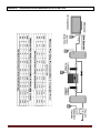
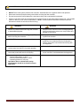
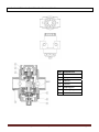
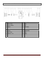
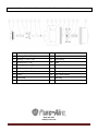
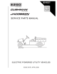
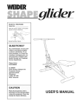
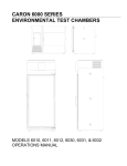
Installation, Operation and Maintenance Manual System Flow Controller “SFC” © 2012 Pure-Aire System Flow Controller Operation Manual - # M-SFC-10 Page 1 GENERAL INFORMATION Pure-Aire is a global leader in the design and manufacturing of products for the drying and purification of compressed air and gas. Our product line includes pressure flow controllers, fluid coolers, water separators, compressed air filters, refrigerated air dryers and heatless, patented zero-purge and heat reactivated desiccant air dryers. Please review this detailed and comprehensive instruction manual for the use of Pure-Aire system flow controllers (SFC). Operational information is supplied for the user and supporting information for the technical personnel who maintains the compressed air system. It is recommended that all who operates or installs the flow controller should carefully read all sections of this manual before commencing with the installation. Thank you for choosing Pure-Aire to service your compressed air needs. Please call if we can be of further assistance. IMPORTANT Warranty registration will improve the parts availability with your Local Authorized Dealer and Service Center and extend the warranty. (800) 274-3233 www.pure-aire.net © 2012 Pure-Aire System Flow Controller Operation Manual - # M-SFC-10 Page 2 TABLE OF CONTENTS Design Concept ........................................................................................................................................................ 4 Diagram # 1: Compressed Air Recommended Installation Flow ........................................................................ 5 Safety Warnings & Precautions.............................................................................................................................. 6 Receiving & Start-Up Review .................................................................................................................................. 7 Pressurization & Start-Up Procedure .................................................................................................................... 8 Trouble Shooting Guide .......................................................................................................................................... 9 Low Plant or Flow Control Pressure. ...................................................................................................... 9 High Flow Control Discharge Pressure. ................................................................................................. 9 Unstable Flow Control Discharge Pressure. .......................................................................................... 9 1.5” Flow Control Valve Parts List: SFC-500 & SFC-750 .................................................................................. 10 1.5” Flow Control Valve Service Drawing & Parts List: SFC-500 & SFC-750.................................................. 11 2” Flow Control Valve Parts List: SFC-1000 & SFC-2000 ................................................................................. 12 2” Flow Control Valve Service Drawing & Parts List: SFC-1000 & SFC-2000................................................. 13 © 2012 Pure-Aire System Flow Controller Operation Manual - # M-SFC-10 Page 3 DESIGN CONCEPT The Pure-Aire System Flow Controller’s (SFC) design, consistently delivers +/- 1% of pressure set point. Most plant air systems have an ever changing fluctuation of demand and changes in plant air pressure. Peak air demands will draw from the air system and tend to disrupt the air capacity. The Pure-Aire SFC will show a direct compressed air system improvement when installed in conjunction with an adequate supply side storage tank. The system will utilize the new supply side storage tank installed with the compressors operating at an appropriately set control pressure and the SFC will deliver the desired plant air pressure set point. Peak air consumptions will be drawn from storage and less compressor HP will be required for peak events. Install the flow control system at the intermediate point of the compressed air system. Install downstream from the filtration, drying equipment & air receiver storage and upstream from the main piping distribution system. The flow controller constantly monitors air pressure as it is delivered to production and releases air from the receiver storage as needed to maintain a continuous, stable air pressure supply. © 2012 Pure-Aire System Flow Controller Operation Manual - # M-SFC-10 Page 4 DIAGRAM # 1: COMPRESSED AIR RECOMMENDED INSTALLATION FLOW © 2012 Pure-Aire System Flow Controller Operation Manual - # M-SFC-10 Page 5 SAFETY WARNINGS & PRECAUTIONS DO NOT service the system pressure flow controller, associated filters or equipment while under pressure. Disconnect electrical (and pneumatic) power before servicing the flow controller. Eye and ear protection should always be used when working with compressed air equipment. Failures on the SFC valves and components can result in a large air loss and/or high pressure loss. One possible reason for failures is from a lack of maintenance. NOTE: Recommended maintenance schedule should be followed to minimize the chances of this occurring. WARNING WARNING 1. Relieve air pressure before servicing flow controller or associated equipment. 1. Always use two wrenches when installing/tightening piping connections to prevent over torque stress and damage to connection. 2. Disconnect power and Lockout/Tagout (LOTO) before servicing flow controller. 2. Always read and follow instructions before servicing system flow controller. 3. NOT SAFE for human respiration (breathing). 3. Comply with electrical installation and service guidelines for the National Electrical Codeand the Federal, State and Local Codes when working with this equipment. 4. Condensate automatic drains are recommended to remove water from the SFC for proper operation. 4. Follow the Pressurization Procedures. 5. Secure drain lines to prevent bodily injury due to unsecured pressurized drain lines whipping. 5. Review the operations of the automatic drains for proper removal of condensate/water drainage daily. 6. Standard designed operations for a unit are: - Ambient temperature of 100°F. - Inlet air process temperature of 100°F. - Operating pressure of 100 psig. Operations above or below these design specifications should be reviewed for proper application. © 2012 Pure-Aire System Flow Controller Operation Manual - # M-SFC-10 Page 6 RECEIVING AND START-UP REVIEW RECEIVING & INPSECTION: Inspect SFC carefully upon arrival. Uncrate and inspect for concealed damage. Any damage should be notified to the freight carrier immediately on the freight bill. File claims with the freight carrier immediately and notify Pure-Aire’s Sales Department. WARNING DO NOT install, operate, maintain, adjust or service this unit without thoroughly reading this manual. All SFC’s are tested and inspected at the factory prior to shipping. Improper operation will cause poor results or mechanical failures from the SFC. SFC LOCATION: Locate the SFC in an area accessible for maintenance. The area should be clean, cool and well lighted. Ambient temperature should be between 50ºF and 100ºF. The SFC should have clearance on all sides for service. See dimensional print for specific clearance requirements. INSTALLATION: (See typical installation drawing) Pure-Aire recommends that an inline strainer be installed on the inlet side of the SFC to guard against contaminants and ensure proper operation. Condensate automatic drains are recommended to remove water from the SFC for proper operation. 1. The SFC unit has air "IN" and "OUT" connections with labels and/or directional flow arrows cast right into the control element. Orient the SFC unit in accordance with compressed air system flow. 2. The SFC unit can be installed in any place. The headers are capable of supporting the weight of the unit for either vertical or horizontal mounting. Do Not support the unit from the flow control valves or the associated control piping. Always use two wrenches when installing piping connections to prevent over torque stress and damage to connection when tightening. 3. Install a 3-valve bypass around the SFC to allow routine maintenance and insure that compressed air will always be available for plant use. A bypass can be supplied with the SFC unit as an option or can be field installed using full line size service valves. As the primary design of the control valves are for precision control of positive flow conditions, backpressure caused by having higher pressure on the downstream side of the SFC than the supply side should be avoided. LEAK TEST: Pressurize system and check the installation for leaks before starting. WARNING Air from system is not safe for human respiration (breathing). DISCLAIMER OF WARRANTY If this unit is used to produce breathing air, OSHA 29 CFR 1910.134 specifications of the necessary equipment and special precautions to make breathing air MUST be used or any warranties are VOID and manufacturer disclaims any liability whatsoever for loss, personal injury or damage. © 2012 Pure-Aire System Flow Controller Operation Manual - # M-SFC-10 Page 7 PRESSURIZATION & START-UP PROCEDURE This procedure is to be followed every day at start-up: Prior to start-up, check for unusual pressure drops and piping restrictions to the SFC flow controller, air receiver and from the air OUT connection of the SFC to the main plant system. Pressure operations and the air compressor system fluctuations may change dramatically after the SFC unit is put on-line resulting in consequential events. In most cases, air compressor controls and set points may require adjustments. During start-up, relief valves in the air receiver storage tank system may open. Observe operation during start-up. Open the 3-valve bypass around the system flow controller. Turn the ADJUSTMENT control valve to the full clockwise position, this will open the SFC flow control valves. The adjustment control valve will be mounted on the SFC or it can be mounted in the remote control panel (if the remote control panel option is supplied/purchased). While leaving the isolation valves open, slowly close the bypass valve around the SFC. Turn the adjustment control valve counter clockwise slowly to dial in the desired discharge pressure. Turn the SFC adjustment in small pressure changes allowing the system to stabilize between adjustments. Failure to adjust the SFC in this manner may result in a system pressure drawdown. The "AIR OUT" gauge displays discharge pressure of the SFC unit. Maximum inlet pressure is shown on the SFC nameplate. Maximum regulating pressure is 5 psi below the lowest operating compressor inlet pressure. NOTE: If the instrument air or adjustment controls air pressure is disconnected, the control valves will close. OPTIONAL REMOTE CONTROL PANEL: Mount the control panel where most convenient for the operator. The appropriately labeled connections are on the control panel. Do not exceed 150 feet from the SFC header to the control panel. Consult factory for greater distances. Pilot air tubing between the SFC piping header and the control panel is ¼” OD and must be bubble tight. See the general arrangement drawing for control panel pneumatic connections. LEAK TEST: Pressurize system and check the installation for leaks before starting. SHUTDOWN PROCEDURE ISOLATION & DEPRESSURIZATION: The following should be completed if the SFC is being shut down for a weekend/shift: Slowly isolate the SFC with the manual bypass open and the inlet/outlet isolation valves closing. Open the bypass valve to allow process flow to continue downstream, then close the SFC outlet isolation valve. At this time, the SFC is isolated and can be depressurized for servicing. Leave drain valves open while servicing. To restart, follow the “PRESSURIZATION & START-UP PROCEDURE”. WARNING © 2012 Pure-Aire ALWAYS REMOVE ALL PRESSURE AND DISCONNECT ALL POWER BEFORE SERVICING UNIT. System Flow Controller Operation Manual - # M-SFC-10 Page 8 TROUBLE SHOOTING GUIDE LOW PLANT OR SFC FLOW CONTROL PRESSURE REMEDY Verify the operations of all the air compressors in the system are operating correctly. Make adjustments or repairs to the compressors. The pneumatic control tubing is leaking or damaged. Repair the leak. Adjustment control valve is defective. Replace the ACV and inspect all of the valves. Controls have stuck in the closed position. Check the control valves for contamination. If necessary, clean and perform annual service. HIGH SFC FLOW CONTROL DISCHARGE PRESSURE REMEDY Bypass valve is open. Make adjustments or repairs. Adjustment control valve is defective. Replace the ACV and inspect all of the valves. Controls have stuck in the OPEN position. Check the control valves for contamination. If necessary. clean and perform annual service. UNSTABLE SFC FLOW CONTROL DISCHARGE PRESSURE REMEDY The inlet air pressure is within 2 to 4 psi of the discharge air pressure set point. Make adjustments or repairs to the compressors. The pneumatic control tubing is leaking or damaged. (This line should be bubble-tight.) Repair the leak. Adjustment control valve is defective. Replace the ACV and inspect all of the valves. Controls valves are contaminated and/or the valve internals have been damaged over time. Perform annual service. © 2012 Pure-Aire System Flow Controller Operation Manual - # M-SFC-10 Page 9 1.5” FLOW CONTROL VALVE PARTS LIST: SFC-500 & SFC-750 KEY © 2012 Pure-Aire DESCRIPTION 1 Cap Kit 2 Spring 3 Valve Kit 4 Head Kit 5 Diaphragm Kit * 6 Retaining Ring 7 Dome System Flow Controller Operation Manual - # M-SFC-10 Page 10 1.5” FLOW CONTROL VALVE SERVICE DRAWING & PARTS LIST: SFC-500 & SFC-750 KEY DESCRIPTION KEY DESCRIPTION 1 Valve, O-Ring 11 Valve 2 Pushnut Fastener 12 Cap 3 Support 13 Valve Spring 4 Diaphragm 14 Cap O-Ring 5 Holder 15 Head 6 O-Ring 16 Retaining Ring 7 Stem O-Ring 17 Dome 8 Retainer x 1/16 W 18 Spring 9 Stem 19 Pitot Tube 10 Screw - Allen Plug © 2012 Pure-Aire System Flow Controller Operation Manual - # M-SFC-10 Page 11 2” FLOW CONTROL VALVE PARTS LIST: SFC-1000 & SFC-2000 KEY © 2012 Pure-Aire DESCRIPTION 1 Cap 2 Valve Spring 3 O-Ring 4 O-Ring 5 Valve 6 Head 7 Valve Stem 8 O-Ring 9 O-Ring 10 Retaining Ring 11 O-Ring 12 O-Ring 13 Piston 14 O-Ring 15 Dome System Flow Controller Operation Manual - # M-SFC-10 Page 12 2” FLOW CONTROL VALVE SERVICE DRAWING & PARTS LIST: SFC-1000 & SFC-2000 KEY DESCRIPTION 1 KEY 1 DESCRIPTION 1 O-Ring (2 /8 ID x /8 W) 10 Valve Stem 2 O-Ring (1 1/4 ID x 1/8 W) 11 Valve Spring 1 3 O-Ring (5 ID x /8 W) 12 Head 4 O-Ring (3 7/8 ID x 3/16 W) 5 13 Dome (Teflon Coated) 1 1 14 Piston 1 1 O-Ring (1 /4 ID x /8 W) 6 O-Ring (1 /4 ID x /16 W) 15 Bias Spring 7 Valve 16 Cap (Teflon Coated) 8 Valve Seat 17 Allen Plug 9 Retaining Ring (800) 274-3233 www.pure-aire.net © 2012 Pure-Aire System Flow Controller Operation Manual - # M-SFC-10 Page 13