1
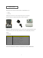
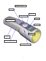
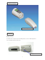
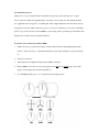
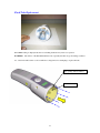
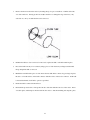
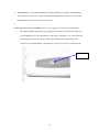
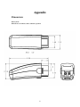
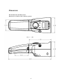
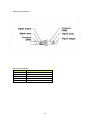
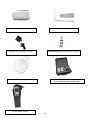
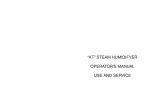
Table of Contents
Introduction . . . . . .. …………………………………………………………………………………….1
Features
Safety Warning……………………………………………………………………………………………2
Servicing and Repair …………………………………………………………………………………….3
Getting Started……………………………………………………………………………………………4
Accessories
Stroboscope Overview……………………………………………………………………………………5
Description of Parts………………………………………………………………………………………6
Operation………………………………………………………………………………………………….7
True RPM……..……………………………………………………………………………………..8
Internal Triggering Mode……………………………………………………………………………9
External Triggering Mode…………………………………………………………………………..9
Adjusting Flash Rate………………………………………………………………………………...10
Phase Shift Function………………………………………………………………………………..11
Tachometer Mode Function…………………………………………………………………………12
Flash tube Replacement……………………………………………………………………………..13
Charging the Battery………………………………………………………………………………….15
Troubleshooting ………………………………………………………………………………………….17
Appendix
Dimensions
Battery ……………………………………………………………………………………………….18
DT-900 Techstrobe…………………………………………………………………………………..19
Phono Connector …………………………………………………………………………………………20
Specification & Accessories………………………………………………………………………………21
Mode Displays……………………………………………………………………………………………...23
Application Pictures ………………………………………………………………………………………24
Table of Contents
OPERATIONS MANUAL
INTRODUCTION
Thank you for purchasing this Shimpo product. This manual explains how to operate your equipment
safely and correctly.
This manual covers the DT-900 Techstrobe series of the Shimpo Stroboscope.
In this manual, you will learn the many features and capabilities of this hand held stroboscope.
Kindly read this manual thoroughly before operation as it holds important information that will help you
fully utilize this unit.
Specifications of this product are subject to change without notice.
DT-900 SERIES
FEATURES
•
The new DT-900 Series is an addition to the growing family of reliable Shimpo test equipment.
•
Ergonomically designed to meet the needs of our customers.
•
Lightweight and versatile, can be carried easily.
•
Can be operated with one hand, or mounted on a tripod.
•
Includes an external connector for remote triggering.
•
Adjustable flash rates that can be doubled and divided in half by using buttons and a rotary dial.
•
Alphanumeric LCD with user friendly features.
•
Complete with charger and spare bulb.
•
Optional plastic case and accessories are available. Please contact your dealer for pricing and options.
Check appendix for additional features.
1
WARNING READ CAREFULLY BEFORE OPERATING UNIT.
For Safety and proper operation, please read this manual carefully. For additional information please call
Shimpo Instruments at (800) 842-1479.
•
Failure to operate this equipment correctly could result in malfunction or accidents.
•
Be sure to operate this stroboscope as described in this manual.
•
Keep this manual handy so as to be ready for use when necessary.
•
If the stroboscope fails to operate, review the operational procedure and troubleshooting section. If
this fails to remedy the problem, contact your nearest dealer.
•
DT-900 handheld stroboscope operates at HIGH VOLTAGE inside the lamp and the electronic
compartment. Please disconnect battery prior to lamp replacement.
•
Direct view of the lamp may trigger epileptic seizure
•
Eye damage may result in improper use of the lamp, please use best judgement in using this
equipment.
•
Damage due to the use of other AC adapter beside the one provided will void the warranty. Kindly
make sure that your AC adapter is Shimpo approved.
•
Remove battery pack prior to recharging. Do not use the adapter as an external source for the
techstrobe.
•
It is recommended that the battery be charged when the “Low Batt” indicator flashes on display. This
is to prolong the life of your battery.
2
SERVICING AND REPAIR
This equipment is free of defects prior to shipment; each strobe is tested and checked to guarantee proper
operation. Repairs beyond changing the lamp and battery pack should be performed by a qualified Shimpo
technician.
This limited warranty period is one year from date of acquisition with proof of purchase. Unit should be
used in context with its design. Modification and misuse will void the warranty.
For inquiries and repair, please contact Shimpo Instruments at (800) 842-1479. Authorization number must
be obtained to properly document repairs and warranty issues. Returns made without prior authorization
maybe refused.
Nidec-Shimpo America
Shimpo Instruments Division
1701 Glenlake Avenue
Itasca, IL 60143
You can also visit us at WWW.SHIMPOINST.COM
3
GETTING STARTED
Each package should contain the following in addition to the DT-900 Stroboscope.
•
Charger
•
Spare lamp
Additional parts such as sensors, holster, and spare battery pack are sold separately.
Optional carrying case is available. Please check your dealer for information
Damage due to shipping should be directed to your local dealer. Please notify them immediately if unit is
damaged upon receipt. Have all receiving documentation ready for expediting damage claim due to
shipping.
ACCESSORIES
Part Number
FLASHTUBE900
DT-900-1
DT-900-2
DT-900-3
DT-900-4
DT-900-5
DT-900-6
DT-900-8
Description
FLASH TUBE REPLACEMENT DT-900
REPLACEMENT BATTERY DT-900
120V AC 60 HZ, AC ADAPTER
LENS REPLACEMENT
HANDLE PAD, REPLACEMENT
PLASTIC CARRYING CASE
HOLSTER, PADDED
UNIVERSAL AC ADAPTER WITH WORLD PLUGS
PLEASE SEE APPENDIX FOR ADDITIONAL INFORMATION AND KIT COMBINATIONS.
4
Do not store instrument on the following places
•
Explosive or combustible areas
•
Near water, oil, dust and chemicals.
•
Areas where temperature is above 104 degrees Fahrenheit (40 degrees Centigrade)
Do not disassemble or repair unit while in operation.
STROBOSCOPE OVERVIEW
Stroboscopes are used in various applications such as quality machine inspection and timing. At highspeed or high frequency operation the human eye can not discern a single image of a moving object.
Stroboscopes are used to freeze these images by matching the speed of the moving object with short
duration flashes. An indicator or reference point such as a small tape or paint mark can be visually rotated
in any direction depending on the phase angle and flash rate it is subjected into.
The Shimpo DT-900 Techstrobe has many of the same capabilities as our DT-300 and DT-700 series
stroboscopes, without the size; these capabilities are incorporated in this unit so as to enjoy these features
with the mere touch of a button.
Check diagram of the parts overview to gain familiarity with this strobe.
5
DESCRIPTION OF PARTS
Power Button
Adjustment Dial
Flash rate divided ÷2
Mode Control
Flash rate multiplied X2
Power Indicator
Phase Control
Battery Pack
Rechargeable
Easy tab for Battery Pack removal
External triggering connector
6
Strobe-Battery Pack Separated
AC Adapter Charger Connector
OPERATION
Mounting Stroboscope
To mount the strobe on a tripod (or any other mounting surface), use screw ¼ -20unc, length 8mm or
shorter for the tripod screw hole on the bottom.
`
Mounting Screw Hole ¼ x 20unc
7
True RPM Measurement
Shimpo Stroboscopes are DUAL function instruments that give the operator the illusion of “stopped
motion” where in actuality the equipment under observation is in a moving state. By adjusting the flash
rate, equipment in motion appears to be standing still. With a slight adjustment, movement can be viewed
in apparent slow motion, which enables the operator or observer to study the process in action. All Shimpo
Stroboscopes can also measure rotational (RPM) or reciprocating (strokes per minute) speeds with the same
high precision as with an electronic digital tachometer.
To measure true revolutions per minute (RPM):
1.
“Mark” the object to be measured by either visually noting an inherent distinguishing characteristic
(such as a label, scratch, etc.) or physically marking the object with a small piece of tape, pencil mark,
etc.
2.
Turn power switch on.
3.
Adjust flash rate from highest Flash per minute (FPM ) downward.
4.
The true RPM can be noted once the action appears frozen and the first single image of the “mark”
appears (see diagram below for further explanation).
5.
To verify RPM reading, press “÷2”. A single image should appear again.
8
Internal Triggering Mode
To use the DT-900 stroboscope in internal triggering mode:
1.
Turn power switch on.
2.
Press “MODE” button and the power indicator will light up, the tachometer is default to internal mode.
Unless there are sensors connected to the external signal connector, the display will show “EXT.Mode
No Signal”. Press mode again to select “TachMode”, then press mode again for “Internal mode”.
3.
Aim light beam at object under observation. The optimal distance between the strobe and moving
object is approximately 2 feet.
4.
Measure RPM by turning the dial to adjust the flashing rate to the rotational speed of the object.
NOTE: To achieve a particular RPM or FPM quickly, use the “x2” or “÷2” switches and then the dial for
fine-tuning.
External Triggering Mode
To use the DT-900 stroboscope in external triggering
mode:
1.
Firmly plug in external sensor. This unit accepts
TTL Logic, high of +5V and low of 0V.
2.
Turn power switch on.
3.
Press “MODE” button to select External Mode option. Power indicator will light up and automatically
detect the presence of an external source of signal, otherwise the indicator will lit up to red to indicate
absence of external source of signal
FPM
Flash indicator will flash in correspondence with input signal. The input signal will be
displayed as FPM (Flash per Minute). Check Appendix for Additional Information
Ext.Mode
no
input
External Mode, automatically look for an external source of
signal. If source is found, LED power indicator will light up
green otherwise it will be red, and the message “no input”
appears. Maximum 12,500 FPM, Minimum 15 FPM. If max
value is exceeded the strobe will stop flashing but the clock
source frequency will continue to be displayed.
9
Phono Style Connector Information:
The phono connector is 3.5mm in diameter size. Stereotype tip, it is the signal output from the strobe and
ring is the signal input to the strobe (Check Diagram Above). Electrically the signals are TTL logic levels,
0-5 V swing, high impedance.
Adjusting Flash Rate
1.
2.
After powering on the strobe, you can adjust the flash rate in 2 ways:
•
Use the central dial to spin to the desired rate.
•
Use the “x2” and “÷2” buttons to increase or decrease the rate.
Turn the dial counter clockwise to decrease the flash rate. Turn the dial clockwise to increase the
flash rate. Flash step is 0.5 flash per turn of the knob.
3.
The faster you turn the dial, the faster the rate will change.
4.
Press the “x2” button to double the current flash rate. For example, if the strobe is set to 1000 FPM,
pressing the “x2” button will change the rate to 2000 FPM.
5.
Press the “÷2” button to reduce the flash rate in half. For example, if the strobe is set at 5000 FPM,
pressing the “÷2” button will change the rate to 2500 FPM.
10
6.
If the “x2” or “÷2” buttons are pressed and the calculated rate is beyond the range of 40-12,500 FPM,
the flash rate will be set to the limit of the strobe. For example, if the strobe is set to 8000 FPM,
pressing the x2 button will change the rate to 12,500 FPM.
NOTE: The DT900 is only limited to the following FPM
Max Flash: 12,500 FPM
Min Flash: 40 FPM (Internal Triggering Mode)
Min Flash: 15 FPM (External Triggering Mode)
Phase Shift Function
The Phase Shift function button is used to read the angular delay or advancement in degrees between the
trigger signal and the actual speed of the moving object.
Phase shifting is used to examine the entire circumference of a gear or reciprocating machine while in
operation. This important handy feature that allows the operator to examine the object in motion, providing
a “real time” view for predictive and preventive maintenance.
The operator can rotate the view by changing the phase of the strobe flash.
1.
Lock onto the desired speed by adjusting the strobe flash rate until the object appears stationary.
2.
Enter the “Phase Mode” by pressing the Phase button. The display will show “Phase: 0 deg”.
3.
Rotate the knob counter clockwise to decrease the phase angle. Turn the knob clockwise to
increase the phase angle. Angle is change by 5 degrees by each step on the dial.
Alternatively, you can spin the phase angle using the “x2” and “÷2” buttons. Hold down the “x2”
button to spin positively through the phase angles. Hold down the “÷2” button to spin negatively
through the phase angles. Releasing the button will stop and hold the last phase angle.
4.
Press “Phase button” again to exit the Phase Shift Mode and return to normal operation.
11
Tachometer Mode
In Tachometer Mode the strobe will not flash but can be used like a Shimpo handheld tachometer. The
DT-900 Techstrobe will display the frequency of the signal source connected to it.
1.
To use the tachometer mode, power the strobe “On” and press the “Mode button” until
“TachMode” is displayed.
2.
Connect a signal source to the external signal connector (Seeplease refer to the description of
parts page) using a stereo type phono connector. Review phono connector signal description
(See Phono style connector information under External triggering section).
3.
If no valid signal source is detected, the strobe will display “TachMode – no input” and the
LED will be red.
4.
If a valid signal source is detected, the DT-900 Techstrobe LCD will display the signal rate
and the LED will be green.
5.
For tachometer mode, the maximum signal rate is 59,000 FPM and the minimum signal rate is
40 FPM.
6.
To exit tachometer mode and return to normal strobe operation, disconnect the signal source
and press the “Mode button” once.
TachMode
no
input
Tachometer Mode, automatically look for an external source
of signal. If source is found, LED power indicator will light up
green otherwise it will be red, and the message “no input”
appears. Maximum 59,000 FPM, and the minimum is 40 FPM.
12
Flash Tube Replacement
When FPM reading is displayed but unit is not flashing, flash tube may need to be replaced:
WARNING: The surface of the DT-900 TechStrobe lens especially the bulb can get hot during continued
use. Caution should be taken to allow sufficient cooling time before attempting to replace the bulb.
Pry opening with screwdriver
Protective Lens
13
1.
Remove the front lens from the strobe by inserting the tip of a pen, screwdriver or similar device into
one of the vent holes. Gently pry the lens out (Be careful not to damage the edge of the lens.). Pry
each side out, one by one until the lens can be removed.
2.
NOTE: The reflector does not need to be removed to replace the bulb. It should remain in place.
3.
Protect the bulb from any oil or residue by using a piece of cloth between your fingers and the bulb.
Grasp and pull the bulb to remove it
4.
Handle the new bulb with a piece of cloth. Insert the new bulb in the connector by pressing it in place.
Be sure to orient the red dot on the bulb connector with the red dot on the strobe connector. If the bulb
is inserted backwards, it will fail to operate as specified.
5.
Ensure the bulb is centered in the reflector.
6.
Re-install the protective lens. Line up the four tabs of the lens with the four slots of the strobe. Insert
one tab in place, and then press the lens back into the strobe so that the remaining tabs snap into place.
14
Charging the Battery
If the battery is low, the stroboscope will not turn on completely and the display will eventually disappear.
It is recommended to recharge the battery once the message “LOW BATT flash on screen. Charge battery
as follows:
1.
Turn power off.
2.
Push the two tabs on the sides of the DT-900 Techstrobe to release the battery. Always remove the
battery from the DT-900 Techstrobe before charging.
Tab release for rechargeable battery pack
3.
Insert AC adapter/charger plug into the strobe receptacle (CAUTION: Charge the unit only with the
Shimpo provided AC adapter/charger).
15
4.
The LED indicator on the handle will light up, indicating the battery is charging. Normal charging
time is within 2 to 4 hours. It is strongly recommended charging the battery fully before using. Red
LED light will turn off after the battery is fully charge.
5.
NOTE: The adapter/charger may NOT be used as a power supply to power the strobe continuously.
If the LED is flashing when the charger is plugged into the battery, it means that the battery has
been discharged below its safe charging level. The charger will attempt to recover the battery by
trickle charging. If it is successful, the charger will continue with the regular charge time,
otherwise it will continue flashing. If this happens you may need to replace your battery pack.
LED Indicator
16
Troubleshooting
FPM reading is displayed but unit is not flashing:
Flash tube may need to be replaced (See Flash tube replacement section)
Stroboscope is in external trigger mode, with no flash:
Check flash tube
Check Sensor
Check wire continuity
Check phono connector wiring (see phono connector section), possible loose connection
Stroboscope is in internal trigger mode, no flash:
Check flash tube
Check battery and recharge if needed.
Stroboscope will not turn on completely
Check Battery, it may need to be charged.
The DT-900 Techstrobe may have reached Max Flash Rate, triggering auto shutoff feature. The DT900 Techstrobe will shutoff after 60 seconds if no buttons are pressed, or the dial knob is not turned. If
the Max Flash rate is reached, allow a couple of minutes to make adjustments.
Allow the unit to cool down if unit turns off due to high flash rate and continuous operation.
Red LED flashing from Battery while charging
Continue charging, the battery has been drained below its safe charging level
Observe the LED indicator, it should stop flashing after a couple of minutes if flashing does not stop
charger can not recover battery by trickle charging. A replacement is needed.
IMPORTANT: Remove battery pack prior to charging.
IF AFTER PERFORMING THE PROCEDURES ABOVE AND THE DT-900 TECHSTROBE IS
STILL NOT WORKING, CONTACT YOUR DEALER FOR SERVICE INFORMATION.
Warranty
1 YEAR LIMITED WARRANTY
See enclosed warranty card with the DT-900 Techstrobe for details.
17
Appendix
Dimensions
Battery Pack
Dimensions are in Inches, unless otherwise specified.
18
Dimensions
DT-900 Dimensions with Battery Pack
Dimensions are in Inches, unless otherwise specified
19
Phono Connector DT-900
Phono Jack Information
Phono Connector Description DT-900
Size
3.5mm
Type
Stereo
Signal Input
Tip
Signal Output
Ring
Ground
Lower end of the Jack
20
Accessories
Part Number
FLASHTUBE900
DT-900-1
DT-900-2
DT-900-3
DT-900-4
DT-900-5
DT-900-6
DT-900-8
Description
FLASH TUBE REPLACEMENT DT-900
REPLACEMENT BATTERY DT-900
120V AC 60 HZ, AC ADAPTER
LENS REPLACEMENT
HANDLE PAD, REPLACEMENT
PLASTIC CARRYING CASE
HOLSTER, PADDED
UNIVERSAL AC ADAPTER WITH WORLD PLUGS
21
DT-900-1 Replacement battery for DT-900.
DT-900-4 Handle Pad, Replacement.
DT-900-2 120V AC 60 HZ, AC Adapter
FLASHTUBE900, Replacement Flashtube DT-900
DT-900-5, Carrying Case for DT-900
Can be purchased with two battery pack
DT-900-3, Lens Replacement
DT-900-6 Holster, Padded
22
Mode Displays
Message
LOW BATT
1200.0
Low Battery indicator, needs recharging. Although the
Stroboscope will continue to flash it is recommended that you
charge the battery when this message appears. Approximately
2.5 hours of continuos use per charge
RPM
Ext.Mode
no
input
TachMode
TachMode
no
input
External Mode, automatically look for an external source of
signal. If source is found, LED power indicator will light up
green otherwise it will be red, and the message “no input”
appears. Maximum 12,500 FPM, Minimum 15 FPM. If max
value is exceeded the strobe will stop flashing but the clock
source frequency will continue to be displayed.
Tachometer Mode, automatically look for an external source
of signal. If source is found, LED power indicator will light
up green otherwise it will be red, and the message “no input”
appears. Maximum 99 rpm, and the minimum is 15 rpm.
23
Application Pictures
ROTATIONAL SPEED OF SHAFT
WITH THE USE OF AN INDICATOR MARK YOU CAN FREEZE AND CHECK THE SPEED OF A
MOVING SHAFT.
24
DRILL INSPECTION/RPM
CHAIN INSPECTION /RPM
25
ROTATIONAL SPEED OF MOTOR
GAP INPSECTION OF ROTOR AND STATOR, THIS IS GOOD FOR QC/QA NOISE REDUCTION
AND ISPECTION OF DAMAGE DUE TO UNBALANCE SPACING.
26
27
28
29