1
An Oracle White Paper
July 2007
Beginners Guide to
Oracle VM Server for SPARC:
Understanding and Deploying Logical Domains
Important note: this paper was originally published before the acquisition of Sun Microsystems
by Oracle in 2010. The original paper is enclosed and distributed as-is. It refers to products
that are no longer sold and references technologies that have since been re-named.
BEGINNERS GUIDE TO LDOMS:
UNDERSTANDING AND DEPLOYING
LOGICAL DOMAINS
for Logical Domains 1.0 release
Tony Shoumack, Systems Group Software Engineering
Sun BluePrints™ OnLine — July 2007
A Sun CoolThreads™ Technology Solution
Part No 820-0832-21
Revision 2.1, 10/9/2007
Edition: July 2007
Copyright © 2007 Sun Microsystems, Inc., 4150 Network Circle, Santa Clara, California 95054, U.S.A. All rights reserved.
Sun Microsystems, Inc. has intellectual property rights relating to technology embodied in the product that is described in this document. In
particular, and without limitation, these intellectual property rights may include one or more of the U.S. patents listed at http://www.sun.com/
patents and one or more additional patents or pending patent applications in the U.S. and in other countries.
U.S. Government Rights - Commercial software. Government users are subject to the Sun Microsystems, Inc. standard license agreement
and applicable provisions of the FAR and its supplements.
Parts of the product may be derived from Berkeley BSD systems, licensed from the University of California. UNIX is a registered trademark in
the U.S. and in other countries, exclusively licensed through X/Open Company, Ltd.
Sun, Sun Microsystems, the Sun logo, Java, Solaris, JumpStart, Netra, OpenBoot, Sun Fire, SunSolve, Sun BluePrints, Sun Blade, Sun Ultra,
and SunVTS are service marks, trademarks, or registered trademarks of Sun Microsystems, Inc. in the U.S. and other countries.
All SPARC trademarks are used under license and are trademarks or registered trademarks of SPARC International, Inc. in the U.S. and other
countries. Products bearing SPARC trademarks are based upon architecture developed by Sun Microsystems, Inc.
Products covered by and information contained in this service manual are controlled by U.S. Export Control laws and may be subject to the
export or import laws in other countries. Nuclear, missile, chemical biological weapons or nuclear maritime end uses or end users, whether
direct or indirect, are strictly prohibited. Export or reexport to countries subject to U.S. embargo or to entities identified on U.S. export exclusion
lists, including, but not limited to, the denied persons and specially designated nationals lists is strictly prohibited.
DOCUMENTATION IS PROVIDED "AS IS" AND ALL EXPRESS OR IMPLIED CONDITIONS, REPRESENTATIONS AND WARRANTIES,
INCLUDING ANY IMPLIED WARRANTY OF MERCHANTABILITY, FITNESS FOR A PARTICULAR PURPOSE OR NON-INFRINGEMENT,
ARE DISCLAIMED, EXCEPT TO THE EXTENT THAT SUCH DISCLAIMERS ARE HELD TO BE LEGALLY INVALID.
------------------------------------------------------------------------------------------------------------------------------------------------------------------------------------------Copyright © 2007 Sun Microsystems, Inc., 4150 Network Circle, Santa Clara, California 95054, Etats-Unis. Tous droits réservés.
Sun Microsystems, Inc. détient les droits de propriété intellectuels relatifs à la technologie incorporée dans le produit qui est décrit dans ce
document. En particulier, et ce sans limitation, ces droits de propriété intellectuelle peuvent inclure un ou plus des brevets américains listés à
l’adresse http://www.sun.com/patents et un ou les brevets supplémentaires ou les applications de brevet en attente aux Etats - Unis et dans
les autres pays.
Des parties de ce produit pourront être dérivées des systèmes Berkeley BSD licenciés par l’Université de Californie. UNIX est une marque
déposée aux Etats-Unis et dans d’autres pays et licenciée exclusivement par X/Open Company, Ltd.
Sun, Sun Microsystems, le logo Sun, Java, Solaris, JumpStart, Netra, OpenBoot, Sun Fire, SunSolve, Sun BluePrints, Sun Blade, Sun Ultra,
et SunVTS sont des marques de fabrique ou des marques déposées de Sun Microsystems, Inc. aux Etats-Unis et dans d’autres pays.
Toutes les marques SPARC sont utilisées sous licence et sont des marques de fabrique ou des marques déposées de SPARC International,
Inc. aux Etats-Unis et dans d’autres pays. Les produits portant les marques SPARC sont basés sur une architecture développée par Sun
Microsystems, Inc.
Les produits qui font l’objet de ce manuel d’entretien et les informations qu’il contient sont regis par la legislation americaine en matiere de
controle des exportations et peuvent etre soumis au droit d’autres pays dans le domaine des exportations et importations. Les utilisations
finales, ou utilisateurs finaux, pour des armes nucleaires, des missiles, des armes biologiques et chimiques ou du nucleaire maritime,
directement ou indirectement, sont strictement interdites. Les exportations ou reexportations vers des pays sous embargo des Etats-Unis, ou
vers des entites figurant sur les listes d’exclusion d’exportation americaines, y compris, mais de maniere non exclusive, la liste de personnes
qui font objet d’un ordre de ne pas participer, d’une facon directe ou indirecte, aux exportations des produits ou des services qui sont regi par
la legislation americaine en matiere de controle des exportations et la liste de ressortissants specifiquement designes, sont rigoureusement
interdites.
LA DOCUMENTATION EST FOURNIE "EN L’ETAT" ET TOUTES AUTRES CONDITIONS, DECLARATIONS ET GARANTIES EXPRESSES
OU TACITES SONT FORMELLEMENT EXCLUES, DANS LA MESURE AUTORISEE PAR LA LOI APPLICABLE, Y COMPRIS NOTAMMENT
TOUTE GARANTIE IMPLICITE RELATIVE A LA QUALITE.
Please
Recycle
i
Sun Microsystems, Inc.
Table of Contents
Preface . . . . . . . . . . . . . . . . . . . . . . . . . . . . . . . . . . . . . . . . . . . . . . . . . . . . . v
Introduction . . . . . . . . . . . . . . . . . . . . . . . . . . . . . . . . . . . . . . . . . . . . . . . . . . . v
Intended Audience . . . . . . . . . . . . . . . . . . . . . . . . . . . . . . . . . . . . . . . . . . . . . v
How This Document Is Organized . . . . . . . . . . . . . . . . . . . . . . . . . . . . . . . . . v
Other Sources of Information . . . . . . . . . . . . . . . . . . . . . . . . . . . . . . . . . . . . .vi
Typographic Conventions . . . . . . . . . . . . . . . . . . . . . . . . . . . . . . . . . . . . . . . .vi
Shell Prompts . . . . . . . . . . . . . . . . . . . . . . . . . . . . . . . . . . . . . . . . . . . . . . . . vii
Ordering Sun Documents . . . . . . . . . . . . . . . . . . . . . . . . . . . . . . . . . . . . . . . vii
Accessing Sun Documentation Online . . . . . . . . . . . . . . . . . . . . . . . . . . . . . vii
Acknowledgments. . . . . . . . . . . . . . . . . . . . . . . . . . . . . . . . . . . . . . . . . . . . . vii
Concepts and Architecture . . . . . . . . . . . . . . . . . . . . . . . . . . . . . . . . . . . . . 1
1 Introduction to Logical Domains . . . . . . . . . . . . . . . . . . . . . . . . . . . . . . . 1
What Are Logical Domains? . . . . . . . . . . . . . . . . . . . . . . . . . . . . . . . . . . . . . . 1
How Do Logical Domains Assist in the Data Center?. . . . . . . . . . . . . . . . . . . 1
Where and When to Use Logical Domains?. . . . . . . . . . . . . . . . . . . . . . . . . . 2
Scenario 1 - Combining Several Small UNIX and Linux Servers . . . . . . . . 3
Scenario 2 - Using Different Kernels . . . . . . . . . . . . . . . . . . . . . . . . . . . . . 4
Scenario 3 - Managing Independent Kernels . . . . . . . . . . . . . . . . . . . . . . . 4
Scenario 4 - Providing Maximum Isolation and Security . . . . . . . . . . . . . . 4
Scenario 5 - Allowing Mixed Access to Devices . . . . . . . . . . . . . . . . . . . . . 5
Scenario 6 - Combining Many Environments on a Single System . . . . . . . 6
Scenario 7 - Replacing Multiple Legacy Servers . . . . . . . . . . . . . . . . . . . . 6
Conclusion . . . . . . . . . . . . . . . . . . . . . . . . . . . . . . . . . . . . . . . . . . . . . . . . . . . 6
2 Logical Domains Architecture Overview. . . . . . . . . . . . . . . . . . . . . . . . . 9
Heart of Logical Domains . . . . . . . . . . . . . . . . . . . . . . . . . . . . . . . . . . . . . . . . 9
SPARC Hypervisor and sun4v Architecture . . . . . . . . . . . . . . . . . . . . . . . . 9
Deciding What to Partition . . . . . . . . . . . . . . . . . . . . . . . . . . . . . . . . . . . . 11
What Is a Logical Domain?. . . . . . . . . . . . . . . . . . . . . . . . . . . . . . . . . . . . 11
Logical Domain Roles. . . . . . . . . . . . . . . . . . . . . . . . . . . . . . . . . . . . . . . . . . 11
Control Domain . . . . . . . . . . . . . . . . . . . . . . . . . . . . . . . . . . . . . . . . . . . . . 12
Service Domain . . . . . . . . . . . . . . . . . . . . . . . . . . . . . . . . . . . . . . . . . . . . 13
I/O Domain . . . . . . . . . . . . . . . . . . . . . . . . . . . . . . . . . . . . . . . . . . . . . . . . 13
Guest Domain. . . . . . . . . . . . . . . . . . . . . . . . . . . . . . . . . . . . . . . . . . . . . . 13
How Do Logical Domains Communicate? . . . . . . . . . . . . . . . . . . . . . . . . . . 13
Virtual Machine Description . . . . . . . . . . . . . . . . . . . . . . . . . . . . . . . . . . . . . 14
Virtual Devices . . . . . . . . . . . . . . . . . . . . . . . . . . . . . . . . . . . . . . . . . . . . . . . 14
CPU . . . . . . . . . . . . . . . . . . . . . . . . . . . . . . . . . . . . . . . . . . . . . . . . . . . . . 14
Memory. . . . . . . . . . . . . . . . . . . . . . . . . . . . . . . . . . . . . . . . . . . . . . . . . . . 15
I/O Devices . . . . . . . . . . . . . . . . . . . . . . . . . . . . . . . . . . . . . . . . . . . . . . . . 15
Beginners Guide to LDoms — July 2007
ii
Sun Microsystems, Inc.
Networking . . . . . . . . . . . . . . . . . . . . . . . . . . . . . . . . . . . . . . . . . . . . . . . . 17
Console. . . . . . . . . . . . . . . . . . . . . . . . . . . . . . . . . . . . . . . . . . . . . . . . . . . 19
Cryptographic Devices . . . . . . . . . . . . . . . . . . . . . . . . . . . . . . . . . . . . . . . 19
Reconfiguration - Dynamic and Otherwise . . . . . . . . . . . . . . . . . . . . . . . . . . 19
Security. . . . . . . . . . . . . . . . . . . . . . . . . . . . . . . . . . . . . . . . . . . . . . . . . . . . . 20
OpenBoot PROM . . . . . . . . . . . . . . . . . . . . . . . . . . . . . . . . . . . . . . . . . . . 21
3 Guidelines and Gotchas . . . . . . . . . . . . . . . . . . . . . . . . . . . . . . . . . . . . . 23
Introduction . . . . . . . . . . . . . . . . . . . . . . . . . . . . . . . . . . . . . . . . . . . . . . . . . . 23
Guidelines. . . . . . . . . . . . . . . . . . . . . . . . . . . . . . . . . . . . . . . . . . . . . . . . . . . 23
Resource Requirements for Control Domains . . . . . . . . . . . . . . . . . . . . . 23
Resource Requirements for I/O and Service Domains . . . . . . . . . . . . . . . 23
How Many Domains Do I Need? . . . . . . . . . . . . . . . . . . . . . . . . . . . . . . . 24
Gotchas . . . . . . . . . . . . . . . . . . . . . . . . . . . . . . . . . . . . . . . . . . . . . . . . . . . . 24
Core/Thread Affinity Model on CMT Systems . . . . . . . . . . . . . . . . . . . . . 24
Additional Applications in the Control and Service Domains . . . . . . . . . . 26
Cryptographic Devices and Virtual CPUs . . . . . . . . . . . . . . . . . . . . . . . . . 26
Other Resource Management Techniques and Logical Domains . . . . . . 27
Network Install Onto a Virtual Disk Devices . . . . . . . . . . . . . . . . . . . . . . . 27
Summary . . . . . . . . . . . . . . . . . . . . . . . . . . . . . . . . . . . . . . . . . . . . . . . . . . . 27
Do’s. . . . . . . . . . . . . . . . . . . . . . . . . . . . . . . . . . . . . . . . . . . . . . . . . . . . . . 27
Don’ts . . . . . . . . . . . . . . . . . . . . . . . . . . . . . . . . . . . . . . . . . . . . . . . . . . . . 27
Section I Wrap Up. . . . . . . . . . . . . . . . . . . . . . . . . . . . . . . . . . . . . . . . . . . . . 28
Implementation and Management. . . . . . . . . . . . . . . . . . . . . . . . . . . . . . . 29
4 Set Up a System to Use Logical Domains. . . . . . . . . . . . . . . . . . . . . . . 31
Overview. . . . . . . . . . . . . . . . . . . . . . . . . . . . . . . . . . . . . . . . . . . . . . . . . . . . 31
Obtain the Correct Build of the Solaris OS . . . . . . . . . . . . . . . . . . . . . . . . . . 31
Check the Solaris OS Version . . . . . . . . . . . . . . . . . . . . . . . . . . . . . . . . . 31
Patch Solaris to Include the Latest Logical Domains Support . . . . . . . . . . . 31
Ensure You Have the Correct Firmware Version . . . . . . . . . . . . . . . . . . . . . 33
Check Firmware Versions. . . . . . . . . . . . . . . . . . . . . . . . . . . . . . . . . . . . . 33
Update the Firmware Version . . . . . . . . . . . . . . . . . . . . . . . . . . . . . . . . . . 34
Install the Logical Domains Manager and Security Packages . . . . . . . . . . . 35
Download and Unpack the Archived Files . . . . . . . . . . . . . . . . . . . . . . . . 35
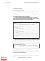
Run the install-ldm Script . . . . . . . . . . . . . . . . . . . . . . . . . . . . . . . . . . . . . 35
Setting Up User Access to Run ldm Commands . . . . . . . . . . . . . . . . . . . 36
Quick Test of the Logical Domains Manager . . . . . . . . . . . . . . . . . . . . . . 37
Create Default Services . . . . . . . . . . . . . . . . . . . . . . . . . . . . . . . . . . . . . . 37
Perform Initial Setup of the Control Domain . . . . . . . . . . . . . . . . . . . . . . . . . 38
Set Control Domain Resources . . . . . . . . . . . . . . . . . . . . . . . . . . . . . . . . 38
Create and Use the New Configuration . . . . . . . . . . . . . . . . . . . . . . . . . . 39
Beginners Guide to LDoms — July 2007
iii
Sun Microsystems, Inc.
Reboot the Solaris OS to Make Logical Domains Ready to Use . . . . . . . 39
Enable the Virtual Network Terminal Server Daemon . . . . . . . . . . . . . . . 40
Final Check. . . . . . . . . . . . . . . . . . . . . . . . . . . . . . . . . . . . . . . . . . . . . . . . 40
Summary . . . . . . . . . . . . . . . . . . . . . . . . . . . . . . . . . . . . . . . . . . . . . . . . . . . 40
5 How to Create Your First Logical Domain. . . . . . . . . . . . . . . . . . . . . . . 43
Introduction . . . . . . . . . . . . . . . . . . . . . . . . . . . . . . . . . . . . . . . . . . . . . . . . . . 43
Having a Plan . . . . . . . . . . . . . . . . . . . . . . . . . . . . . . . . . . . . . . . . . . . . . . . . 43
How Many Domains? . . . . . . . . . . . . . . . . . . . . . . . . . . . . . . . . . . . . . . . . 44
Domain Names . . . . . . . . . . . . . . . . . . . . . . . . . . . . . . . . . . . . . . . . . . . . . 44
Operating System . . . . . . . . . . . . . . . . . . . . . . . . . . . . . . . . . . . . . . . . . . . 45
CPU and Memory Resources . . . . . . . . . . . . . . . . . . . . . . . . . . . . . . . . . . 45
Networking . . . . . . . . . . . . . . . . . . . . . . . . . . . . . . . . . . . . . . . . . . . . . . . . 45
Boot Disk Devices. . . . . . . . . . . . . . . . . . . . . . . . . . . . . . . . . . . . . . . . . . . 46
Console Device. . . . . . . . . . . . . . . . . . . . . . . . . . . . . . . . . . . . . . . . . . . . . 46
Command Line Steps . . . . . . . . . . . . . . . . . . . . . . . . . . . . . . . . . . . . . . . . . . 47
Logical Domains Manager (ldm) . . . . . . . . . . . . . . . . . . . . . . . . . . . . . . . . 47
Creating a Guest Domain . . . . . . . . . . . . . . . . . . . . . . . . . . . . . . . . . . . . . 48
Review Steps . . . . . . . . . . . . . . . . . . . . . . . . . . . . . . . . . . . . . . . . . . . . . . 49
Verify the Configuration . . . . . . . . . . . . . . . . . . . . . . . . . . . . . . . . . . . . . . 51
Save the Configuration . . . . . . . . . . . . . . . . . . . . . . . . . . . . . . . . . . . . . . . 53
6 Reconfiguration - Moving Resources Around . . . . . . . . . . . . . . . . . . . 55
Dynamic Reconfiguration of VCPUs . . . . . . . . . . . . . . . . . . . . . . . . . . . . . 56
Delayed Reconfiguration of Memory . . . . . . . . . . . . . . . . . . . . . . . . . . . . 56
Summary . . . . . . . . . . . . . . . . . . . . . . . . . . . . . . . . . . . . . . . . . . . . . . . . . . . 57
Domain Specification . . . . . . . . . . . . . . . . . . . . . . . . . . . . . . . . . . . . . . . . 57
Command Line Actions to Create myldom1 . . . . . . . . . . . . . . . . . . . . . . . 57
Reconfiguration. . . . . . . . . . . . . . . . . . . . . . . . . . . . . . . . . . . . . . . . . . . . . 58
Section II Wrap Up . . . . . . . . . . . . . . . . . . . . . . . . . . . . . . . . . . . . . . . . . . . . 59
Reference Information . . . . . . . . . . . . . . . . . . . . . . . . . . . . . . . . . . . . . . . . 61
7 Logical Domains Administration Commands . . . . . . . . . . . . . . . . . . . . 63
Overview. . . . . . . . . . . . . . . . . . . . . . . . . . . . . . . . . . . . . . . . . . . . . . . . . . . . 63
Command Syntax . . . . . . . . . . . . . . . . . . . . . . . . . . . . . . . . . . . . . . . . . . . . . 63
8 Frequently Asked Questions . . . . . . . . . . . . . . . . . . . . . . . . . . . . . . . . . 67
Introduction . . . . . . . . . . . . . . . . . . . . . . . . . . . . . . . . . . . . . . . . . . . . . . . . . . 67
Technology, Features, and Definitions . . . . . . . . . . . . . . . . . . . . . . . . . . . . . 67
Platform Support and Operating System . . . . . . . . . . . . . . . . . . . . . . . . . . . 68
Architecture - Hypervisor, Control, I/O, and Service Domains . . . . . . . . . . . 69
CPU and Memory . . . . . . . . . . . . . . . . . . . . . . . . . . . . . . . . . . . . . . . . . . . . . 70
Boot Process . . . . . . . . . . . . . . . . . . . . . . . . . . . . . . . . . . . . . . . . . . . . . . . . 71
Performance . . . . . . . . . . . . . . . . . . . . . . . . . . . . . . . . . . . . . . . . . . . . . . . . . 72
Beginners Guide to LDoms — July 2007
iv
Sun Microsystems, Inc.
Systems Management and Monitoring . . . . . . . . . . . . . . . . . . . . . . . . . . . . . 72
9 Five-Minute Guides . . . . . . . . . . . . . . . . . . . . . . . . . . . . . . . . . . . . . . . . . 73
Introduction . . . . . . . . . . . . . . . . . . . . . . . . . . . . . . . . . . . . . . . . . . . . . . . . . . 73
Installation, Setup, and Removal . . . . . . . . . . . . . . . . . . . . . . . . . . . . . . . . . 73
Installing Logical Domains Manually. . . . . . . . . . . . . . . . . . . . . . . . . . . . . 73
Removing Logical Domains Packages and Resetting System . . . . . . . . . 74
Reset to Factory Defaults via the Service Processor . . . . . . . . . . . . . . . . 75
Updating Firmware Without a Local FTP Server . . . . . . . . . . . . . . . . . . . 75
Creating a Logical Domain . . . . . . . . . . . . . . . . . . . . . . . . . . . . . . . . . . . . 76
Security. . . . . . . . . . . . . . . . . . . . . . . . . . . . . . . . . . . . . . . . . . . . . . . . . . . . . 76
Rolling Back Solaris Security Toolkit Profiles . . . . . . . . . . . . . . . . . . . . . . 76
I/O and Disks . . . . . . . . . . . . . . . . . . . . . . . . . . . . . . . . . . . . . . . . . . . . . . . . 77
Using a File as a Virtual Disk . . . . . . . . . . . . . . . . . . . . . . . . . . . . . . . . . . 77
Using ZFS With Virtual Disks . . . . . . . . . . . . . . . . . . . . . . . . . . . . . . . . . . 77
Creating a Split PCI Configuration on a Sun Fire T2000 Server . . . . . . . 82
Section III Wrap Up. . . . . . . . . . . . . . . . . . . . . . . . . . . . . . . . . . . . . . . . . . . . 84
10 Beginners Guide Wrap Up . . . . . . . . . . . . . . . . . . . . . . . . . . . . . . . . . . 85
Summary . . . . . . . . . . . . . . . . . . . . . . . . . . . . . . . . . . . . . . . . . . . . . . . . . . . 85
11 About the Author . . . . . . . . . . . . . . . . . . . . . . . . . . . . . . . . . . . . . . . . . . 87
12 Index . . . . . . . . . . . . . . . . . . . . . . . . . . . . . . . . . . . . . . . . . . . . . . . . . . . . 89
Beginners Guide to LDoms — July 2007
v
Sun Microsystems, Inc.
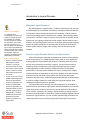
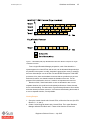
What’s In the Sidebar?
Preface
In this sidebar, you can find
useful information providing the
background to various topics
shown in the text, definitions of
important terms, and references
for more information.
Introduction
Pay close
attention to these
concepts as they
can help you later
with other topics.
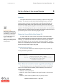
This guide is intended to assist you in gaining an understanding of how to
easily and effectively deploy Sun’s Logical Domains, or LDoms1, technology. It
can help you determine how and where to use logical domains to the greatest
effect using best practices.
This guide discusses strategies for deploying logical domains on the following
These topics can
have implications
for the
performance of
your system.
supported platforms and the various best practices for these platforms:
This section
contains
information
regarding the
security of your
system.
• Netra™ T2000 Server
This section
contains new
information or
some handy
facts.
This section
contains
administration
concepts.
• Sun Fire™ or SPARC® Enterprise T1000 Server
• Sun Fire or SPARC Enterprise T2000 Server
• Sun SPARC® Enterprise T5120 and T5220 servers
• Netra CP3060 Blade
• Sun Blade™ T6300 T6320 Server Modules
The guide works through step-by-step examples that include the commands
to set up, deploy, and manage logical domains and looks at commonly asked
questions and advanced techniques.
The information and methodologies presented in this document are suitable
for version 1.0 of the Logical Domains software.
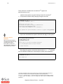
Intended Audience
This guide is intended to be used by systems administrators and other
technical staff wanting to understand and use Logical Domains. Additionally, it
Take care with
the commands in
this section.
might be useful for less technical users in gaining an understanding of concepts
and overall architecture. This guide does not require prior Solaris™ Operating
System (OS) or LDoms-specific knowledge, only a general understanding of the
You can find
more information
about this in the
“Five-Minute
Guides” section.
UNIX® or Linux operating system and some command-line experience.
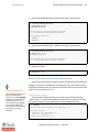
How This Document Is Organized
This guide is designed for several different levels of user and intended to be
used as both an introduction to concepts and technologies, and serve as a handy
Hints to help
make your work
easier.
reference for more complex approaches.
This guide is divided into three sections:
• Section 1 - Logical Domains Concepts and Architecture
You can find
more information
in the “Frequently
Asked Questions”
section.
This section helps you understand what logical domains are, what they can do,
and how you might make the best use of them.
1.This guide uses the terms partitions, logical domains, domains, and LDoms interchangeably.
Beginners Guide to LDoms — July 2007
vi
Sun Microsystems, Inc.
• Section 2 - Implementation and Management
This section guides you, step-by-step, through the process of getting your
system ready to support the Logical Domains Manager and then creating and
administering your first logical domains.
• Section 3 - Reference
This section provides advanced techniques and methodologies in the form of
“Frequently Asked Questions” and "Five- Minute Guides" to serve as a
reference.
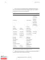
Other Sources of Information
The following documents have been used in preparing this guide and may
provide additional information regarding the concepts presented:
Title
Author and Publisher Location
Logical Domains (LDoms) 1.0
Administration Guide
Sun Microsystems, Inc. http://docs.sun.com
“Developing and Tuning Applications on
UltraSPARC T1 Chip Multi-threading
Systems”
Denis Sheahan
Sun Blueprints Online
http://www.sun.com/
blueprints
“Solaris Containers: What They Are and
How to Use Them”
Menno Lageman
Sun Blueprints Online
http://www.sun.com/
blueprints
Table 1. References
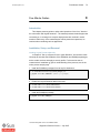
Typographic Conventions
The following table describes the different fonts and their meanings when
used in this guide:
Typeface
Meaning
Example
AaBbCc123
Command line arguments such as Type prstat -J to see processes
files and directories.
by project.
AaBbCc123
Typed input
machine_name% ls -la
AaBbCc123
Place holder to be replaced by a
real value.
To list processes by a specific
project, type prstat -j
projectid
AaBbCc123
Refer to the Logical Domains
Concepts and words to be
emphasized or references to other (LDoms) 1.0 Administration Guide
sources of information
for more information.
Table 2. Typographic Conventions
Beginners Guide to LDoms — June 2007
vii
Sun Microsystems, Inc.
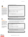
Shell Prompts
The following table shows the different system prompts and their meanings
when used in this guide:
Shell/System
Prompt
Bourne and Korn shell prompt
$
Bourne and Korn shell superuser prompt
#
OpenBoot™ prompt
{0} ok
System controller prompt
sc>
Table 3. Command and Shell Prompts
Ordering Sun Documents
The SunDocsSM program provides more than 250 manuals from Sun
Microsystems, Inc. If you live in the United States, Canada, Europe, or Japan, you
can purchase documentation sets or individual manuals through this program.
Accessing Sun Documentation Online
The docs.sun.com web site enables you to access Sun technical
documentation online. You can browse the docs.sun.com archive or search for
a specific book title or subject. The URL is:
http://docs.sun.com/
To reference Sun BluePrints OnLine articles, visit the Sun BluePrints OnLine
Web site at:
http://www.sun.com/blueprints/online.html
Acknowledgments
This guide was prepared with the assistance of the entire Sun Logical
Domains development team, who provided feedback, guidance, additional
content, and factual review. Additionally I would like to specifically thank several
people, without whom this guide would have not been completed: Narayan
Venkat who provided working examples for the virtual I/O section; Liam Merwick
who assisted with technical content; Eric Sharakan for helping to clarify the
Logical Domains Manager functions and configurations; Jeff Savit for input into
several areas and ZFS examples; and Janet Daugherty who provided invaluable
assistance for a first time author in preparation, critique, and copy-editing.
Beginners Guide to LDoms — July 2007
viii
Sun Microsystems, Inc.
Beginners Guide to LDoms — June 2007
Sun Microsystems, Inc.
SECTION I
Concepts and Architecture
Chapter 1 - Introduction to Logical Domains
Chapter 2 - Logical Domains Architecture Overview
Chapter 3 - Guidelines and Gotchas
Beginners Guide to LDoms — July 2007
2
Sun Microsystems, Inc.
Beginners Guide to LDoms — July 2007
1
Sun Microsystems, Inc.
Introduction to Logical Domains
1
What Are Logical Domains?
Sun Microsystems’ Logical Domains, or LDoms, technology is part of a suite
What Is Consolidation?
In computing terms,
consolidation is the process of
combining multiple resources
and activities into a smaller
number of locations, systems,
and procedures. This can be
done for many reasons: to
improve efficiency by increased
use, to reduce real estate and
utilities costs with fewer systems
and data centers, and to reduce
administration effort and
complexity by simplifying and
standardizing procedures.
Types of Consolidation:
• Physical - Combine multiple
data centers into fewer
locations. For example,
rather than having 15 small
data centers at each regional
location, combine into three
data centers spread across
the country.
• Logical - Ensure as many as
possible methodologies and
policies for administration,
systems management, and
backup are standardized
across the organization. An
example would be to have a
standard operating system.
• Rationalization - Combine
multiple systems and their
applications into fewer
systems or partitions on a
single system.
of methodologies for consolidation and resource management that includes Sun
Fire Dynamic System Domains and Solaris OS Containers, of which resource
control and operating system virtualization are a subset. This technology allows
you, the user, to allocate a system’s various resources, such as memory, CPUs,
and devices, into logical groupings and create multiple, discrete systems, each
with their own operating system, resources, and identity within a single computer
system. By careful architecture, a logical domains environment can help you
achieve greater resource usage, better scaling, and increased security and
isolation.
How Do Logical Domains Assist in the Data Center?
When considering the application architectures for modern services delivery,
we see that most rely on a multiplexed data model, which is many applications
working together providing data to one another to ultimately produce a service
that can be consumed by an end-user or agency. This can have the result of
producing complex architectures, often requiring multiple systems, because
certain application modules cannot be combined because of compatibility,
performance, or security issues. Whatever the reason, creating many multiple
systems has been an expectation for data center operation in the past. Recently,
pressures such as real estate costs, systems use, and power and cooling
expenses, have seen many vendors developing methodologies and technologies
to combine multiple systems into fewer numbers of physical systems, while
retaining the features required for operation.
The Logical Domains technology can conceivably allow for the creation of
entire data center tiers within a single system. Securely isolated from one another,
logical domains are still able to amortize the various resources of the platform,
CPUs, memory, networking, and storage, with the flexibility to change resource
amounts and configurations on demand. By combining multiple separate systems
into discrete, logical domains, you can increase systems usage and reduce real
estate along with power and cooling requirements, based upon efficiencies in
Beginners Guide to LDoms — July 2007
2
Sun Microsystems, Inc.
platform design and better utilization. This is a key reason for systems
rationalization in data center consolidation techniques.
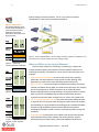
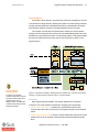
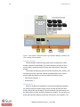
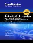
Degrees of Separation?
The following diagrams show
how the levels of separation in
each of Sun Microsystems’
separation technologies
intersect the various layers of a
physical system.
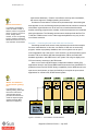
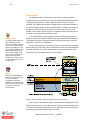
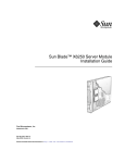
Figure 1. Server Rationalization. The low usage of multiple systems is combined to use
the resources of a single system and raise average usage.
Figure 2. i Solaris OS
Containers/Resource Manager
Where and When to Use Logical Domains?
There are many methods for virtualizing, or partitioning, a system into
multiple discrete operating environments. Each has a different aspect to its
underlying functionality, and therefore, can be used for various purposes. For
example:
• Solaris Resource Management can control the CPU shares, operating
parameters, and other aspects of each process, thereby allowing many
applications to coexist in the same operating system environment.
• Solaris Containers can create multiple virtualized environments (sometimes
referred to as Solaris Zones) within one Solaris kernel structure; thus, keeping
the memory footprint low. Solaris Containers can be used with Solaris
Figure 2. ii Logical Domains
Resource Management to provide flexibility in fine-grained resource controls,
which is good for consolidating large numbers of dynamically resourcecontrolled environments within a single kernel or version of the Solaris OS.
• Sun Fire Dynamic System Domains can create electrically isolated domains
on high-end Sun Fire systems, while offering the maximum security isolation
and availability in a single chassis and combining many redundant hardware
features for high availability. Dynamic System Domains are great for
consolidating a smaller number of mission critical services with security and
availability.
• Logical Domains fit somewhere in the middle of the two previous solutions.
Logical domains offer isolation between the various domains, which is
Figure 2. iii Sun Fire
Dynamic System Domains
achieved through a firmware layer, lowering the hardware infrastructure
Beginners Guide to LDoms — July 2007
3
Sun Microsystems, Inc.
requirements drastically - Great for cost-effective security and consolidation,
with server support for multiple operating environments.
So what to use and where? Given that requirements help in determining the
What Is Virtualization?
best approach to use, the following section presents several scenarios: some that
In computing, virtualization
means to create a virtual, or
abstract, version of a physical
device or resource, such as a
server, storage device,
network, or even an operating
system, where the framework
divides the resource into one or
more execution environments.
show where logical domains can be of most use; some that describe where
another technology might be more suitable; or some that might even be combined
with logical domains. The following scenarios were developed with the Sun Fire
T1000 and T2000 servers in mind. Other supported platforms may vary in their
use of these scenarios.
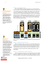
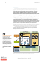
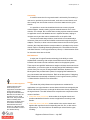
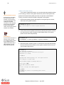
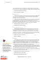
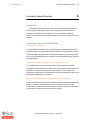
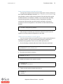
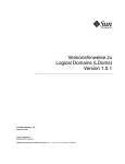
Scenario 1 - Combining Several Small UNIX and Linux Servers
Combining several small servers is the simplest and most obvious example
for server rationalization. In this case, one Solaris 10 OS runs an accounting
program, another a proprietary database, and a Linux system runs an opensource application and a web server. In this scenario, we will create three logical
domains: FIN for the Solaris OS financial application, DB for the Solaris OS
database application, and WEB for the Linux system. We will give slightly more
CPU and memory resources to the DB domain.
Here we can use the SPARC-based, independent software vendor (ISV)
applications directly in the FIN and DB domains because the Sun UltraSPARC-T1
powered servers have full SPARC binary compatibility. As the WEB domain is an
open-source environment, we have the flexibility to recompile the open-source
applications for a Solaris OS, SPARC-based system.
What Is This Additional
Control Domain (primary)
for?
In a nutshell, the control
domain (primary) looks after
the LDoms environment,
communicates with the
processes and firmware to
create the required logical
domains required. (More
about this in Chapter 2.)
Figure 3. Scenario 1 - Consolidation of Small Servers
Beginners Guide to LDoms — July 2007
4
Sun Microsystems, Inc.
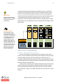
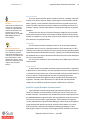
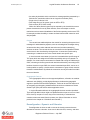
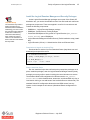
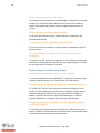
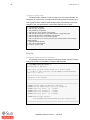
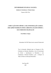
Scenario 2 - Using Different Kernels
TEST, DEVELOPMENT, and QA environments run on the same machine.
TEST runs Solaris 10 N OS and DEVELOPMENT and QA runs the Solaris 10 NWhich Operating Systems
Can I Use With Logical
Domains?
The operating system for a
guest logical domain needs to
support Logical Domains
software and run on an
LDoms-supported platform.
(See the “Introduction” on
page v for a list of platforms
supported by LDoms 1.0
software.) Currently, only the
Solaris 10 11/06 (SPARC) OS
can run with Logical Domains
software.
What Is Resource
Management?
This is a general term for
techniques used to control how
much of a systems’ resources
are allocated to a particular set
of processes or applications,
such as CPU, memory, and
even network bandwidth.
Resource management can be
used to ensure an application
has enough resources to
complete a task in the right
amount of time or hold back
runaway processes from
overwhelming the system. It
can even allow tens or
hundreds of users to coexist on
a system without their
workloads impacting one
another.
1 OS. Solaris Containers are not suitable in this situation as each environment
requires an independent kernel (remember, Solaris Containers use the same
kernel structure). The Logical Domains Manager can do this as each virtualized
system has its own, completely separate, operating system. Hint - You could use
two logical domains, one for TEST and another with two Solaris Containers for
DEVELOPMENT and QA, as follows. This can help reduce the administration
effort, by maintaining only two kernels.
Figure 4. Scenario 2 - Different Kernels in Two Logical Domains Combined With Solaris
Containers
Scenario 3 - Managing Independent Kernels
Similar to the above scenario, if you require an environment where kernels
might need to be patched independently from each other, Solaris Containers on
the same system could not be used. The Logical Domains Manager, however,
could fulfill this task and other situations where various applications cannot be
consolidated in a single environment due to different patch and kernel level
requirements.
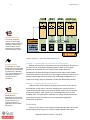
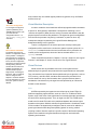
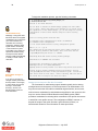
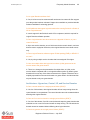
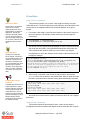
Scenario 4 - Providing Maximum Isolation and Security
Three environments are required: one for a corporate directory server (DIR),
another for a database with an application server (DB), and another for multiple
web servers (WEB). In this scenario, the Logical Domains Manager can provide
Beginners Guide to LDoms — July 2007
5
Sun Microsystems, Inc.
completely separate operating systems and hardware resources, providing a
greater level of isolation than would be the case for Solaris Containers. In this
scenario, the sensitive data possibly contained in the directory and database
What Is SMP?
logical domains would be isolated from the web servers, with the database server
Symmetric multiprocessing
(SMP) systems have multiple
CPUs that can all process
simultaneously.
in a separate Solaris Container for additional security. The web servers
themselves could be in separate Solaris Containers to possibly improve scaling
characteristics, as some applications cannot necessarily take advantage of larger
SMP systems.
Application Scaling
Some applications scale
better than others; that is,
they perform at greater levels
of throughput or speed when
more computing resources
are applied to them. An
example might be a large
database system that can
perform overnight batch jobs
in 2 hours with 4 CPUs, 1.5
hours with 8 CPUs, and 45
minutes with 16 CPUs. This
application does improve
with more resources, but
does not scale linearly.
Figure 5. Scenario 4 - Isolation Methodologies
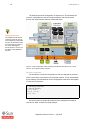
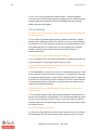
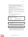
Scenario 5 - Allowing Mixed Access to Devices
Several environments are required, with some needing to access devices
directly, such as a database environment and a disk subsystem. Here the Logical
Domains software approach offers some flexibility in how devices can be
accessed, including virtual access and direct access. It is also possible to create a
virtual storage-area network (SAN) and local-area network (LAN), allowing logical
domains to share devices effectively.
In this scenario, a domain runs a database (DB) and has direct access to the
devices located under the peripheral component interconnect (PCI) controller.
The initial domain then shares access to these devices to two other domains,
APP1 and APP2, creating a virtual SAN. (More about this in the section on virtual
devices.)
Beginners Guide to LDoms — July 2007
6
Sun Microsystems, Inc.
Allocating Resources
On currently supported
systems, up to 32 logical
domains could be created by
allocating 1 thread to each
domain. Memory can be
allocated in increments as
small as 8-kilobyte chunks.
Figure 6. Scenario 5 - Direct and Virtual Access to I/O
Threads and Cores
The allocation of a single
thread within a core to a logical
domain can have implications
for performance, depending
upon your configuration and
workload. See Chapter 3
“Gotchas” for more
information.
Scenario 6 - Combining Many Environments on a Single System
Multiple environments are necessary for a team of developers, all running on
the same version of the Solaris Operating System. While up to 32 logical
domains can be created on 8-core model servers, Solaris Resource
Management combined with Solaris Containers could make a more suitable
choice when resources are needed to a percentage of a thread or need to be reallocated dynamically based on system load. Additionally, management of a
single kernel image might be preferable to reduce the administrative burden.
Scenario 7 - Replacing Multiple Legacy Servers
In this scenario, we are replacing 20 aging servers, some running at less
than 200 Mhz. In this case, a one-to-one mapping from a legacy server to a
logical domain provides many of the features shown in the previous scenarios:
Managing Resources
security and isolation, better resource use, and independent kernel revision
Solaris Resource
Management is a technology
for allocating resources, such
as CPU and memory, to
various processes and
applications within a Solaris
OS instance.
flexibility. (Note: The performance implications of a single thread allocated per
logical domain should be examined to ensure appropriate application
performance is attained.)
Conclusion
As you can see, there are many ways in which logical domains can be used.
The preceding scenarios give you a sense of what is possible with Logical
Beginners Guide to LDoms — July 2007
7
Sun Microsystems, Inc.
Domains software. Later in this guide, we will look at the guidelines that can help
you decide which approach to take. In the next chapters, we will discuss the
architecture of Logical Domains software that makes these scenarios possible.
Beginners Guide to LDoms — July 2007
8
Sun Microsystems, Inc.
Beginners Guide to LDoms — July 2007
Logical Domains Architecture Overview
Sun Microsystems, Inc.
Logical Domains Architecture Overview
9
2
This chapter takes a closer look at the technology that makes it possible to
create logical domains. The chapter also examines the various layers that allow
the Logical Domains technology to partition a system through to the resources
that can be virtualized.
So what does Logical Domains technology do? A simple explanation is:
"Provides the ability to split a single physical system into multiple, independent
virtual systems."
A slightly more detailed explanation is:
"Creates multiple virtual systems by an additional software application in the
firmware layer, interposed between the operating system and the hardware
platform called the hypervisor. It abstracts the hardware and can expose or hide
various resources, allowing for the creation of resource partitions that can operate
as discrete systems, complete with virtual CPU, memory and I/O devices."
This is quite a long explanation, but what does it mean? Let us find out how this is
possible with the layers that provide Logical Domains functionality and the overall
architecture of Sun’s Logical Domains technology.
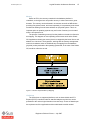
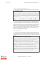
Heart of Logical Domains
SPARC Hypervisor and sun4v Architecture
The hypervisor, a firmware layer on the flash PROM of the motherboard, is a
thin software layer with a stable interface, the sun4v platform, between the
operating system and the hardware. The hypervisor provides a set of support
functions to the operating system, so that the OS does not need to know intimate
details of how to perform functions with the hardware. This allows the operating
system to simply call the hypervisor with calls to the sun4v platform. This is often
described as a stable interface. The interface does not change; therefore, you
have a consistent programming model even if a new generation of machine is
released. For example, if a faster CPU is released, the operating system does not
need to be updated. This layer is very thin and exists only to support the operating
system for hardware-specific details.
More importantly, as the hypervisor is the engine that abstracts the hardware,
it can choose to expose or hide various aspects of the hardware to the operating
system. For example, the hypervisor can expose some CPUs but not others, and
some amount of memory but not all to specific operating systems. The hypervisor
then can create a so-called "virtual machine," which can then run the OpenBoot
PROM stack. Now you have started to subdivide the physical system into logical,
not physical, partitions or logical domains. Importantly, these resources can be
Beginners Guide to LDoms — July 2007
10
Sun Microsystems, Inc.
dynamically reconfigured, which enables adding and removing resources during
operation. Certain revisions of operating systems are able to interact with the
hypervisor during changes and add or remove resources without a reboot.
Additionally, while the hypervisor is responsible for maintaining separation
between domains, it also provides the capability to create channels, through
which domains can communicate with each other (more on this in a later
section).
Things to Remember
Understanding the overall
architecture of Logical Domains
software will help you when
constructing your own logical
domain deployments. Pay
particular attention to the terms
used in this chapter as they will
appear throughout this guide.
Figure 1. The Hypervisor and sun4v Architecture
The hypervisor, with its stable sun4v interface, is the centerpiece to creating
logical domains. Important points to remember are:
Logical Domains Aware
The hypervisor can let the
operating system know
changes are to be made so
that it can sequence properly
and even make some changes
dynamically; therefore, it is
important for the operating
system to be “Logical Domains
aware” so as to support logical
domains features like dynamic
reconfiguration.
• The hypervisor is the layer between the operating system and hardware.
• The hypervisor implements a stable sun4v interface. The operating system
makes calls to the hypervisor, and therefore, does not need to know intimate
details about the hardware, even if the platform changes.
• The hypervisor is very thin; it exists only to support the operating system for
hardware-specific functions, making it small and simple, which assists in
stability.
• The hypervisor creates a virtual machine allowing the system to be partitioned
by exposing some of the resources to a specific partition and hiding others.
Beginners Guide to LDoms — July 2007
Logical Domains Architecture Overview
Sun Microsystems, Inc.
11
• The hypervisor creates communication channels, logical domain channels
(LDCs), between domains to provide a conduit for services such as networks
and shared devices.
Deciding What to Partition
The decision about how to partition the system is based on many factors,
such as:
• Security - How do I want to isolate my applications from one other?
• Devices - How do my applications need to access devices?
• Resources - How much CPU and memory are required for my application?
• Compatibility - Which environments do my applications need to run and are
they able to run together?
Keep It Simple
In many situations, you can
chose to simplify the
deployment of your systems
by combining the control of
the logical domains
environment with the delivery
of devices, too.
What Is a Logical Domain?
The previous section on the hypervisor defined a logical domain as a full
virtual machine, with a set of resources, such as a boot environment, CPU,
memory, and I/O devices, and ultimately, its own operating system. A logical
domain is isolated because of the hypervisor’s capability of being an intermediate
step between the operating system and the hardware resources that need to be
virtualized.
From an architectural standpoint, all domains are created equally: they are all
guests of the hypervisor. They can have differing attributes that are required to
perform a specific function or role.
Logical Domain Roles
There are several different roles for logical domains, and these are mainly
Security and the Control
Domain
defined by context; their usage defines them. A domain may have one or more of
As the control domain is able
to interact with other domains,
stop, start, even remove them
entirely, this domain should be
viewed as similar to the system
controller from a security
perspective. In general, the
control domain should be
hardened and secured using
appropriate techniques.
• Control domain - Creates and manages other logical domains and services by
One such method is to apply
the Solaris Security Toolkit
which is discussed in Section 2
of this guide.
these roles, such as combining the functions of an I/O and service domain:
communicating with the hypervisor.
• Service domain - Provides services, such as a virtual network switch or a virtual
disk service, to other logical domains.
• I/O domain - Has direct ownership of and direct access to physical input/output
devices, such as a PCI Express card or a network device. Can optionally share
those devices to other domains by providing services.
• Guest domain - Presents a virtual machine that subscribes to services provided
by service domains, and is managed by the control domain.
Beginners Guide to LDoms — July 2007
12
Sun Microsystems, Inc.
Control Domain
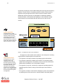
The control domain forms the basis for communications between the
hypervisor, the hardware platform, and the other domains, allowing for the
creation and control of logical domains, services, and devices. The control
domain contains the SUNWldm packages, including the Logical Domains
Manager application and the Logical Domains Manager daemon (ldmd) process
required for managing logical domains. (All these pieces are discussed later.)
Also, the control domain is the first domain created during the Logical Domains
Manager installation procedure, which is described in Section 2.
The interface to the hypervisor is through the command-line interface of the
Logical Domains Manager. The Logical Domains Manager understands the
mapping between the physical and virtual devices, and interacts with the various
components to sequence changes, such as the addition or removal of resources,
and even creation of a logical domain. Additionally, the Logical Domains
Manager communicates these changes to proxy agents located in the supported
operating systems of the guest domains that are undergoing the changes.
The Logical Domains Manager can only be run in the control domain
“primary”. (See Section 2 for more detailed usage of the Logical Domains
Manager command-line interface.)
The Role of the Proxy Agent
The agent or proxy in the
operating system allows
communication of events from
the hypervisor enabling the
operating system to be
informed of actions, such as
the addition and removal of
devices. An OS that supports
such features can then signal
back to the hypervisor that it is
ready for the action to occur.
An example of this is dynamic
reconfiguration in the Solaris
OS.
Figure 2. Control Domain and Logical Domains Manager Architecture
Beginners Guide to LDoms — July 2007
Logical Domains Architecture Overview
Sun Microsystems, Inc.
13
Service Domain
A service domain provides specific virtualized services, including virtual disk,
Resetting Control and I/O
Domains
network, and console services using a LDoms-specific communication channel.
Soft resets of control and I/O
domains are not supported
currently in Logical Domains
software and should not be
performed on a control
domain. Instead, use an ldm
add-config command to
save changes.
which to provide virtual device services, it does not necessarily need them. For
While, typically, a service domain would have access to physical devices from
example, a private, internal virtual switch or virtual console requires no physical
hardware.
As these services all rely on Solaris OS support, ideally the service domain
should have the same revision of the LDoms-enabled Solaris OS as the control
domain for consistency. You can have many services domains, but only two that
have services from physical devices.
I/O Domain
An I/O domain has direct ownership of some or all of the system physical
What Is an I/O Domain
input/output devices, such as a onboard network or fibre channel card in a PCI
The capability for a domain to
be an I/O domain is based
upon direct ownership of one
of the two PCI controllers and
then sharing them to other
domains as a service. This is
discussed in detail later in this
chapter under Virtual I/O
Devices.
controller, and is able to access the I/O device directly from the operating system
rather than through a virtualized device layer. Typically, the I/O domain then takes
the additional role of a service domain and shares the devices to other domains in
the form of virtual devices.
You can have a maximum of two I/O domains, one of which also must be the
control domain.
Guest Domain
A guest domain is a complete virtualized environment that has no ownership
of physical I/O or virtual devices, nor does it provide services to other domains. It
is a subscriber of the resources or services provided to it by the control domain or
a service domain. The guest domain must run an operating system that
understands both the sun4v platform and the virtual devices presented by the
hypervisor. Currently, this is the Solaris 10 11/06 OS with required patches
124921-02 and 125043-01 (with kernel update 118833-36) at a minimum.
How Do Logical Domains Communicate?
Logical domains communicate through logical domain channels, or LDCs.
These are channels of communication by which data can be moved from one
domain to another. The channel is the mechanism by which virtual networks can
be established between logical domains, and it provides the conduit for services,
such as I/O, to be provided to a guest domain. These channels are explicitly
created, defined by the Logical Domains Manager, and bound to the designated
logical domains with specific services at each end of the channel. It is a strict
point-to-point link, rather than the traditional networking paradigm of a port
opening upon request. This helps to make logical domain channels more secure,
Beginners Guide to LDoms — July 2007
14
Sun Microsystems, Inc.
and, because they are created logically within the hypervisor, they are flexible
and fast to set up.
Save Your Configuration
For changes to the physical
system’s partitioning to be
available after a power cycle,
you must save the
configuration with the “ldm
add-spconfig <config_name>”
command.
Virtual Machine Description
In order to create the virtual machines defined by logical domains commands
at power-on, the hypervisor instantiates a configuration containing a set of
“machine descriptions” (MDs) from the service processor that detail the way the
physical system’s resources are partitioned. The hypervisor gets its configuration
from the service processor only during a cold-start, or power-on boot. Any
subsequent changes requested by the Logical Domains Manager are
downloaded directly to the hypervisor.
To store a configuration to the service processor, thereby ensuring the
configuration will be used for the next time the system is power cycled, the “ldm
How to Revert to Defaults
add-spconfig” command needs to be used, and as the service processor can
The default environment is
saved in a configuration called
“factory-default”. Loading this
will mean that any changes to
the partitioning of a system will
be lost, and the configuration
will revert to one where a single
virtual (primary) machine
contains all of the resources
available. Specifically, the
machine will boot up as a
single domain containing all
resources, with no virtual I/O
devices configured. See
Chapter 9: “5-Minute Guides”
for more information on how to
reset your system to factory
defaults.
contain several configurations, these can also be selected with the “ldm setspconfig” command.
These commands are shown in Chapter 4: “Set Up a System to Use Logical
Domains”, and Chapter 5: “How to Create Your First Logical Domain”.
Virtual Devices
Virtual devices are any hardware resources on the system that are
abstracted by the hypervisor and presented to the logical domains on the system.
They can take the form of physical devices partitioned by the hypervisor, such as
CPU, memory, and I/O busses, and those devices that are provided from a
service domain for use by other domains; that is, physical devices that are
translated to virtual devices by the hypervisor and provided by an I/O-service
domain to other domains.
CPU
All CPUs exposed by the hypervisor are referred to as virtual CPUs. On
platforms supporting logical domains, such as a Sun Fire T1000 and T2000
system, each of the cores of the system has four executing threads, represented
as virtual CPUs by the hypervisor. Thus, an eight-core Sun Fire T2000 server
would have 32 virtual CPUs able to be partitioned between the various logical
domains on the system. With this release of Logical Domains 1.0 software, virtual
CPUs are able to be dynamically reconfigured; that is, removed or added to a
guest logical domain while the guest operating system is running, without
requiring a reboot. Note this requires a specific version of the Solaris Operating
System to be installed in the guest domain and might not work with other
operating environments.
Beginners Guide to LDoms — July 2007
Logical Domains Architecture Overview
Sun Microsystems, Inc.
15
Memory
Similar to CPUs, the memory contained in the hardware platform is
virtualized, so the hypervisor can provide memory in various amounts to guest
domains. The memory can be allocated in increments as small as 8KB chunks providing fine-grained control, and most importantly, it is represented to the virtual
machines as starting from the same address as a physical system. This is an
important point as operating systems may not function if memory is not located
where it is expected to be.
The process of translating memory from the platform to domains is referred to
as mapping. This happens in most operating environments such as the Solaris
OS. Applications already see memory that is re-mapped by the kernel from a real
address to a virtual one. The hypervisor, working with the memory management
units in the hardware, takes an additional step of mapping from the hardware
(physical) to that presented to the operating system that, in the case of the Solaris
OS, would be referred to as real.
Figure 3. Virtual-to-Physical Memory Mapping
I/O Devices
The I/O devices on supported platforms, such as internal disks and PCIExpress (PCI-E) controllers and their attached adapters and devices, can be
presented to the various logical domains in several ways. These are based upon
the requirements of the application and the administrative model needed.
Beginners Guide to LDoms — July 2007
16
Sun Microsystems, Inc.
Direct I/O Devices
The traditional model of direct device control by an operating system is
maintained by the Logical Domains model. The Logical Domains software uses a
mode where the hypervisor creates a mapping from the device to a virtual
interface. The software then allows the logical domain to maintain ownership of
the device. With this release of the Logical Domains 1.0 software, the maximum
number of I/O domains allowed is two and one of these must be the control
domain. This is based upon the PCI bus on supported servers consisting of two
ports with various leaf devices attached to them.
In a Logical Domains environment, the PCI-E bus can be programmed to
Make It Flexible
assign each port to two separate domains using the Logical Domains Manager.
Tip: While a guest domain can
take ownership of an I/O
device, use virtualized devices
from an I/O or service domain
where ever possible. You will
have greater flexibility for other
domains to use the devices
and to make changes in the
future. Use direct devices in a
guest domain only when
needed, such as when aiming
for utmost performance from a
storage device.
This enables more than one domain with direct access to physical devices as
opposed to relying on I/O virtualization.
On initial system power-on, the control domain is assigned all of the physical
device resources. Then these can be released and can be owned independently
as PCI-E A and B. In the case of deploying two I/O or service domains, each
could own a PCI root and the devices in the tree below.
Split PCI
See the “Five-Minute Guides”
section for an example of how
to create a Split PCI
configuration to allow two
domains to have direct access
to devices. This is the first step
in creating a second I/Oservice domain
Figure 4. Direct I/O Model, Detailing Ownership at a PCI Root Level
As you can see, this limits the number of domains that can directly own a PCI
Express bus to two, and is one of the reasons for having a virtualized approach to
I/O. Virtual I/O provides the flexibility for more logical domains to have access to
I/O devices, sharing them without direct ownership.
Beginners Guide to LDoms — July 2007
Logical Domains Architecture Overview
Sun Microsystems, Inc.
17
Virtual I/O Devices
In contrast to direct devices, virtual devices provide the capability for devices
to be shared to multiple domains, allowing the creation of virtual storage networks,
thereby providing additional consolidation benefits by rationalization of storage
and interfaces (and the reduction in the administrative burden involved).
The concept of virtual devices is based upon at least one service domain
owning a device through the direct I/O model, and establishing a path to the other
domains by a logical domain channel. The operating system in the guest domains
then sees a virtual device driver with which it can interact as if it were a local,
physical device.
Service-to-Guest
Communications
A service or I/O domain
provides virtual switch services
and virtual network devices to
guest domains, and, by
default, it does not enable the
communication between itself
and guest domains.
Figure 5. Virtualized I/O Model, Showing Devices Shared From a I/O Service Domain
Through a Logical Domain Channel (LDC) to a Guest Domain
Networking
With Logical Domains software, the network adapters are virtualized
resources. The virtual network infrastructure comprises two components:
• Virtual network (vnet) device implements a virtual Ethernet device and
communicates with other vnet devices in the system using the virtual network
switch.
• Virtual network switch (vsw) is a layer-2 network switch that connects the virtual
network devices to the external network and also switches packets between
them.
Beginners Guide to LDoms — July 2007
18
Sun Microsystems, Inc.
Connectivity
A network connection from a guest domain is achieved by first creating a
vsw service, provided by a service domain, such as the control domain, and
then creating vnet devices that connect to it and are attached to the guest
domain.
It is possible to create virtual switches that do not access a physical
network adapter, thereby creating a private network between one or more
domains. For example, this is useful when creating a private network between
an application server and database server in separate domains, helping to
increase security and also reduce network traffic on the public LAN.
The service domain that provides a virtual switch is not automatically a
consumer of the service and has its default connection through the physical
adapters. Therefore, to allow communications between the service and guest
domains, the virtual switch device must be enabled, or plumbed, on the service
domain. Refer to “Enabling Networking Between the Control/Service Domain
and Other Domains” in the Logical Domains (LDoms) 1.0 Administration Guide
for instruction about how to do this.
MAC Addresses
A major part of Logical Domains technology is the ability to create
sophisticated networking, with multiple virtual switches and virtual networks
between both domains and the networks external to the physical system.
These require enough MAC addresses to assign to all these devices and as an
administrator, you have the option to manually assign MAC addresses to these
devices from your own pool of assigned MAC addresses. However Sun
Microsystems has provided other options for assigning MAC addresses for
your virtual switch and network devices. Refer to the discussion of “Assigning
MAC Addresses Automatically or Manually” in the Logical Domains (LDoms)
1.0 Administration Guide for more information.
Lofi Devices Not Supported
Loopback devices (often
known as lofi) are not
supported as virtual disks, and
should not be exported
through the virtual disk server.
Disk files are now able to be
used directly by the virtual
disk server. This provides the
same functionality while
reducing the complexity of the
environment and reducing
administration tasks. See
Chapter 9: ”5-Minute Guides”
for more information on how to
use disk files directly.
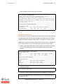
Storage
The virtual disk (vdisk) infrastructure implements a mechanism for
applications in a logical domain to access data on disk drives managed by the
domain with direct I/O access, as though the drives were directly available to
the logical domain. The vdisk infrastructure comprises two components with a
common interface:
• Virtual disk client (vdc) driver, which resides in the logical domain and
provides standard block device access to applications executing in that
domain.
• Virtual disk server (vds) driver, which resides in the service domain and
applies vdisk requests to the corresponding raw disk, file, or disk volume
exported by it. The virtual disk can be based upon several device types,
including:
Beginners Guide to LDoms — July 2007
Logical Domains Architecture Overview
Sun Microsystems, Inc.
19
– An entire physical disk, which could also be a storage partition presented by a
SAN device, sometimes referred to as a logical unit number (LUN)
– Single slice of a disk or LUN
– Disk image file on a file system (such as UFS or ZFS)
– Disk volumes (ZFS, SVM, VxVM)
While all of these devices types may be exported by the virtual disk server to
present virtual disks for use by other domains, some are subject to certain
restrictions such as network installation of the Solaris operating environment. ZFS
for example provides the ability to create emulated volumes that cannot be used
with jumpstart.
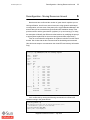
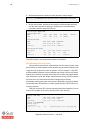
Console
The console has traditionally been the conduit for accessing the system level
messages for administrative purposes, such as reviewing boot messages during
an intervention when other methods cannot be used, as when networking
services are down. The console device as a connection to the OpenBoot PROM
environment is also virtualized by the hypervisor. A connection is achieved by
connecting to a network service in the control domain at a specific port.
A virtual console concentrator (vcc) service is created with a specific range of
TCP ports which are assigned to domains sequentially as they are created. For
example, if a virtual console concentrator is created with a range of 5000 through
5100, connecting to the first guest domain would be achieved by connecting to the
localhost via telnet on port 5000, the second created with port 5001, and so on. It
is also possible to specify a virtual console concentrator to group virtual consoles
to assist in administration. By default the connection can only be made from within
the control domain.
Cryptographic Devices
The cryptographic devices on the supported platforms, referred to as modular
arithmetic units (MAUs), provide high-performance, dedicated cryptographic
engines to perform RSA and DSA operations. These can be used for tasks such
as encrypting and decrypting network traffic that could occur between a Secure
Socket Layer (SSL) web server and an application server.
In Logical Domains software, the cryptographic devices are also virtualized.
There are eight MAU units on eight-core platforms with one per core of four virtual
CPUs. As they are part of a core, they can be bound only to a domain that
contains at least one strand from the parent core. (More information on this is
provided in the chapter on “Guidelines and Gotchas.”)
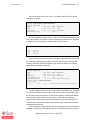
Reconfiguration - Dynamic and Otherwise
Reconfiguration is when we add or remove the virtual resources that are
allocated or bound to a domain. As we can do this with CPU, memory, and other
Beginners Guide to LDoms — July 2007
20
Sun Microsystems, Inc.
resources, it is important to know what can be changed and how. There are
different types of reconfiguration: dynamic and delayed.
• Dynamic Reconfiguration means that we can make the resource changes to a
Reconfigurable Devices
Dynamic reconfiguration allows
one to add or remove
resources while the operating
system is still running.
Currently, only CPUs can be
changed dynamically, and
dynamic reconfiguration must
be supported by the operating
system that is running in the
guest domain.
domain while the domain is up and running and the operating system is
functioning. Being able to do this requires two parts: the hypervisor must be
able to support these changes dynamically and the operating system must be
able to cope with the changes occurring during its operation. Currently only
virtual CPUs can be dynamically reconfigured.
• Delayed Reconfiguration allows changes to be made ready for the next reboot
of the guest operating environment (or stop and start of the logical domain if no
OS is loaded). Multiple delayed reconfiguration operations may be made but
only targeting one domain at a time. After that domain is rebooted, and the
delayed reconfiguration changes are made, reconfigurations may then be
made to other domains. As long as no virtual I/O devices were removed with a
delayed reconfiguration command, you can also cancel a delayed
reconfiguration command. This guide covers more of the process of
reconfiguration (dynamic and delayed) in Section 2, when we set up our first
logical domain.
• Configuration Mode is the initial mode for the environment upon first
installation of the Logical Domains Manager software (or when the machine is
reset to factory default). All changes in this mode are queued and must be
saved in a new machine description (see add-spconfig command in Chapter 4
“Set Up a System to Use Logical Domains”) and are then acted upon at the
next reboot.
The user is made aware of delayed reconfiguration and configuration mode
by messages displayed in the terminal window after issuing logical domains
manager commands.
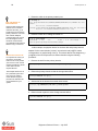
Security
In a typical UNIX computer system like the Solaris OS, several levels of trust
are present. These are similar to the root and user access you might be familiar
with, but these levels are designated by the space they occupy: the user
environment and the kernel environment, which is privileged.
The control domain, which contains the processes involved in creating and
managing logical domains, needs to be secured in a similar way to the system
controller on a hardware multi-domain system. The control domain can affect all
of the logical domains on the system. Logical Domains software, through the
hypervisor, implements an additional level in this trust model of hyperprivileged.
The firmware layer below the virtual machine, the hypervisor, runs at a
hyper-privileged level and the processes in the control domain, such as the
domain management daemons and the Logical Domains Manager, interact with
Beginners Guide to LDoms — July 2007
Logical Domains Architecture Overview
Sun Microsystems, Inc.
21
the firmware layer using logical domain channels. By using so-called hypertraps,
the implementation of logical domain channels to this hyperprivileged mode allow
the hypervisor to control domain processes. This is similar in the way traps are
What Is the OpenBoot
PROM?
used from the user environment to move into the kernel environment.
The OpenBoot™ PROM
system is a powerful firmware
environment that manages the
loading of standalone
programs into memory, such
as an operating system, and
begins executing. The
OpenBoot firmware also
manages hardware, provides
a programming model (a
language called Forth), and
supplies boot-time variables to
control parameters such as
boot devices, security, and
diagnostic levels.
processes run at a greater level of privilege to do their work.
A few notes about a virtual
OpenBoot PROM:
The main concept to understand is that the hypervisor and control domain
OpenBoot PROM
The OpenBoot PROM environment forms the basis for initial program loading
and execution, typically for an operating system. It also provides other features,
such as diagnostics and boot-time parameters, to control operation. In the Logical
Domains software, the OpenBoot PROM environment is virtualized also, and
made available to multiple partitions as discrete boot environments. The
OpenBoot firmware is the basis for running the operating system in a logical
domain.
The OpenBoot {0}ok prompt is the first thing you see when connecting to the
console of a newly created logical domain, and a familiar sight for those
experienced in using Sun’s SPARC hardware.
• All logical domains in a
system will have the same
version of the OpenBoot
firmware.
• The OpenBoot firmware is
not available to debug the
kernel after the OS is
started with Logical
Domains software, because
it is removed from memory.
Fast Booting
An useful side effect of the
virtual OpenBoot PROM
seeing only the resources
allocated to it by the hypervisor
is that it can boot very quickly.
Physical machines must
search through and verify all of
the components of the system,
which can take some time.
With a smaller number of
devices, a logical domain can
be booted and ready for use.
quickly
Beginners Guide to LDoms — July 2007
22
Sun Microsystems, Inc.
Beginners Guide to LDoms — July 2007
Guidelines and Gotchas
Sun Microsystems, Inc.
Guidelines and Gotchas
23
3
Introduction
This section summarizes the various requirements and situations to avoid
when determining a suitable configuration for logical domains deployment. These
deployments will be as varied as the application architectures running on them. In
most cases, testing various approaches is a valid way of confirming the best setup
for your environment.
Guidelines
Resource Requirements for Control Domains
Because the control domain runs the daemon processes and the Logical
Domains Manager, which provides our interface to the hypervisor, we must
ensure that the control domain has adequate CPU and memory resources for the
Logical Domains Manager to function properly. Having other, heavy-weight
applications within this domain, without sufficient compute resources, could affect
the processes that manage and monitor the domains.
A good starting point is to assign a complete core of 4 virtual CPUs and at
least 1GB of memory as a minimum. If the control domain is also providing disk
and other I/O services, see the following section for additional sizing information.
Resource Requirements for I/O and Service Domains
The I/O and service domains provide the actual physical devices, such as
disks and networks as virtualized services to guest domains. Ensure there are
adequate resources available to the I/O and service domains to deal with the
loads that might be placed upon them.
For example, a virtualized disk subsystem under heavy use, might generate
enough I/O loads that a significant proportion of CPU time is required to service
the I/O. If the service domain does not have enough resource to service the I/O,
performance for the guest domain could suffer. Of particular note is when ZFS is
used to deliver disk services, additional memory should be configured for that
service domain. Similarly, high network loads from a guest domain running a
network-intensive application, using a virtual switch service, could keep the CPUs
of an I/O domain quite busy handling the network load.
Assign a complete core of 4 virtual CPUs and at least 4GB of memory when
using ZFS to deliver disk services (or at least 1GB of memory when not using
ZFS) to an I/O or service domain as a minimum, with additional complete cores
assigned for heavier I/O loads.
Beginners Guide to LDoms — July 2007
24
Sun Microsystems, Inc.
How Many Domains Do I Need?
After reviewing the various scenarios in Section 1, you could be getting a
good idea as to where logical domains are most applicable to your environment.
A rough guideline could be determining how many different operating systems
you need to run. This can be determined by many factors including:
• Different patching requirements.
• Different availability requirements.
• Applications that must be separated for architectural or security reasons.
• Security requirements.
• Independent control, such as rebooting - Do we need it?
• Kernel type and versions.
• Disk devices, direct and virtual.
• Networking - Do we need to communicate directly with other logical domains
on the same system?
• Direct and virtual devices - Which does our application need?
• Disk services needed - Do we need a whole disk or a disk image file?
• Cryptographic devices - For example, do we need SSL processing?
These are a lot of questions. However, in attempting to answer these
questions it helps to categorize the requirements and allows you to quickly
determine aspects of the configuration such as:
"If I need direct access to a storage device for my database, then can it
function as a service domain?"
If your answer is no, then you will need another domain to provide services.
Gotchas
Core/Thread Affinity Model on CMT Systems
With Chip Multithreading (CMT) systems, such as the Sun Fire T1000 and
T2000 servers, each of the cores of the system contain multiple processing
threads, or strands, per core. Currently these systems can have up to 8 cores,
each containing 4 hardware threads, each running in sequence to execute a
program thread. Each of the threads in a core work as a team to switch through
the workloads, one each cycle, so it is important to keep the threads together.
This approach is particularly effective for workloads which have many
threads and where performance is impacted to a significant degree by memory
latency. In a CMT system, the impact of memory latency can be reduced by
switching to other processing threads to perform useful work while waiting for
memory.
Beginners Guide to LDoms — July 2007
Guidelines and Gotchas
Sun Microsystems, Inc.
25
Figure 1. UltraSPARC(TM) Chip Multithreaded Execution Model Compared to SingleThreaded Execution
From a Logical Domains Manager perspective, each of the threads in a
system appear to be virtual CPUs, and as such, can be allocated independently to
any domain in the system. In reality, threads are grouped into cores; for example,
there are 4 threads per core in the Sun Fire and SPARC Enterprise T1000 CMT
processors. Also, there are hardware resources that are provided on a per-core
basis and, therefore, are shared between the threads on that core. For the
purposes of this discussion, the level 1 cache is an important such resource.
Because of this, if the threads within a core are allocated to two or more
separate domains, this could lead to suboptimal performance of those threads,
due to cache thrashing. For that reason, to get the best performance from caches
and other shared processor resources, it is best to avoid allocating the threads of
a core to separate domains, if at all possible.
Working Example
1. Set up the control domain with 4 virtual CPUs, all from the first core (the CPU
IDs are 0, 1, 2, and 3).
2. Create a second logical domain with 2 virtual CPUs. The Logical Domains
Manager will add CPU IDs 4 and 5. These will be from the second core.
Beginners Guide to LDoms — July 2007
26
Sun Microsystems, Inc.
3. Create a third logical domain with 4 virtual CPUs having CPU IDs 6, 7, 8, and
9. The Logical Domains Manager will assign two strands from the second
core and two strands from the third core.
This means that processes from unrelated workloads and operating systems
from the second and third logical domains will be competing for the level1 cache
and other chip resources that are provided on a per-core basis. Therefore the
best approach, from a CPU resource perspective, is to create the larger logical
domain first, and then to create the other logical domains in complete cores,
leaving the smaller domains to last.
Additional Applications in the Control and Service Domains
As described more fully in the next section, when upgrading an existing
system to provide logical domains functionality, the pre-existing applications will
be present in the newly established control domain. While you can choose to run
other applications within this domain depending on your requirements, this might
not be desirable, because the security or loading implications might make it
inappropriate to have other pre-existing applications in the control domain. In that
case you may choose to migrate the applications to another domain. However, if
the application, such as a database server, could benefit from direct access to
I/O devices, the best choice may be to run the application in a control or service
domain.
Cryptographic Devices and Virtual CPUs
As we have seen, the virtual cryptographic (crypto) devices belong to a
specific core, and as such, we need to bind them to domains with at least one
thread from the parent core. Because we have 8 crypto devices, we need to
ensure that we allocate them as required, so that we do not put ourselves in a
position of not being able to bind a device to a domain, if needed.
Working Example
1. Build a logical domain that has 14 virtual CPUs created from three complete
cores and one partial core.
2. Bind four cryptos from each of the complete and the partial cores.
3. Create a small, two-CPU logical domain from the remaining threads in the
partially used core.
4. If we tried, we would not be able to bind any cryptos to this logical domain
without adding additional virtual CPUs from cores with free cryptos. The
cryptographic device for the two virtual CPUs is already bound to another
logical domain.
Beginners Guide to LDoms — July 2007
Guidelines and Gotchas
Sun Microsystems, Inc.
27
Other Resource Management Techniques and Logical Domains
If you use processor sets within the Solaris OS in a logical domain, attempting
to remove the last virtual CPU of a processor set using Logical Domains Manager
commands may fail. You need to remove the processors from the set first, from
within the Solaris OS environment.
Network Install Onto a Virtual Disk Devices
Currently, exporting virtual disks backed by ZFS volumes and disk slices do
not allow network installation. To use network installation, you must use a virtual
disk that is backed by a complete disk or image file. These can take the form of a
physical spindle in the system, a LUN located on a SAN device or even a file on
UFS or ZFS local to the control or service domain. Additionally, the operating
system can be transferred from an existing Solaris OS installation to the disk slice
or file-based disk service and used to run a logical domain. The scope of this
procedure is beyond this document.
Summary
Again, there are lots of aspects to consider when configuring domains. To
summarize these:
Do’s
4 Allocate sufficient resources to the control domain so the Logical Domains
Manager and its associated processes can run effectively.
4 Provide enough computing resources to the I/O domain to be able to process
the expected loads of I/O traffic generated by guest domains.
4 Allocate virtual devices to guest domains where possible to improve flexibility.
Assign direct devices only where needed.
4 Be mindful of the relationship between the processing threads of a core, and
ensure the virtual CPUs of a core are all assigned to the same domain where
possible.
4 Use a complete disk if you want to perform a network installation of the Solaris
OS.
Don’ts
8 Don’t forget you need to remove processors from processor sets in a guest
domain operating system before being able to dynamically remove virtual
CPUs from those sets.
Beginners Guide to LDoms — July 2007
28
Sun Microsystems, Inc.
8 Don’t create domains with partially allocated cores (not using all threads in a
core) without first considering whether you want to use cryptographic devices,
and then checking to see if they are free to be bound to your new domain.
Section I Wrap Up
We have covered a lot of material in this section, from methodologies and
business drivers, to Logical Domains architecture, devices, security, and do’s
and don’t’s. In the next section, we move into setting up a system and creating
your first logical domain.
Beginners Guide to LDoms — July 2007
Sun Microsystems, Inc.
SECTION II
Implementation and Management
Chapter 4 - Set up a System to Use Logical Domains
Chapter 5 - How to Create Your First Logical Domain
Chapter 6 - Reconfiguration - Moving Resources Around
Beginners Guide to LDoms — July 2007
30
Sun Microsystems, Inc.
Beginners Guide to LDoms — July 2007
Set Up a System to Use Logical Domains
Sun Microsystems, Inc.
Set Up a System to Use Logical Domains
31
4
Overview
This chapter describes the process of preparing a system for using logical
domains. This process includes checking and updating firmware, checking
operating system revisions, and installing the Logical Domains Manager and
associated packages. Most of the steps shown here require both superuser
access to the Solaris Operating System and administrator access to the system
controller. The following steps set up the control domain, which can communicate
Protect Your Data
This section involves the use
of administrative concepts and
commands. If you are unsure
how to proceed, seek advice,
so you do not damage your
system or lose data.
Take the time to back up your
data if you are working from an
existing system.
with the hypervisor, interact using the command-line interface, and run the various
processes required to create and manage logical domains.
Obtain the Correct Build of the Solaris OS
You must obtain the correct version of the Solaris OS that supports the
Logical Domains Manager and advanced features like dynamic reconfiguration.
Currently, you must have the Solaris 10 11/06 OS. You can use any normal
process of installation for the control domain, including JumpStart™, network,
DVD or CD, or upgrading from a previous version. The process of installing the
Solaris OS is beyond the scope of this guide.
Check the Solaris OS Version
You can check the release of the Solaris OS present on your system by
running the following command:
# cat /etc/release
Solaris 10 11/06 s10s_u3wos_10 SPARC
Copyright 2006 Sun Microsystems, Inc. All Rights Reserved.
Use is subject to license terms.
Assembled 14 November 2006
Patch Solaris to Include the Latest Logical Domains Support
The following three patches must be applied to the Solaris 10 11/06 OS in
order to run Logical Domains software (LDoms networking will not function
correctly without 124921-02):
• 118833-36, Kernel update patch
• 124921-02, which contains updates to the Logical Domains 1.0 drivers and
utilities
• 125043-01, which contains updates to the qcn (console) drivers.
Beginners Guide to LDoms — July 2007
32
Sun Microsystems, Inc.
These patches are available from the SunSolveSM support site:
http://sunsolve.sun.com1
Install the three patches using the following Solaris OS commands.2
1. First quiesce the Solaris OS by changing to single-user mode:
# shutdown -i1 -g0 -y
svc.startd: Changing to state 1.
...
Killing user processes: done.
svc.startd: The system is ready for administration.
Requesting System Maintenance Mode
(See /lib/svc/share/README for more information.)
Root password for system maintenance (control-d to bypass):<root_password>
2. Unpack the downloaded kernel patch 118833-36 and apply it to the system:
Take Care - System
Shutdown
Take care with the following
commands, because they halt
and reboot the system.
Ensure that no others are
using this system and that you
have backed up your data.
# cd <patch_download_directory>
# unzip 118833-36.zip
# patchadd 118833-36
...
Patch 118833-36 has been successfully installed.
See /var/sadm/patch/118833-36/log for details
( output truncated )
Reconfigure the system via a halt and reboot with the “boot -rs3” command
from the OpenBoot PROM prior to attempting any further patch installations:
# shutdown -i0 -g0 -y
...
{0} ok boot -rs
1.SunSolve registration and/or support contracts may be required to download some patches.
2.The revision number of the current patches may differ from the example shown.
3.The “boot” command option “r” causes the system to reconfigure kernel modules, while the
“s” option causes the system to boot into single-user mode, ready for additional patch
installations.
Beginners Guide to LDoms — July 2007
Set Up a System to Use Logical Domains
Sun Microsystems, Inc.
33
3. Unpack the downloaded patch 124921-02 and apply it to the system:
# cd <patch_download_directory>
# unzip 124921-02.zip
# patchadd 124921-02
...
Patch 124921-02 has been successfully installed.
See /var/sadm/patch/124921-02/log for details
Patch packages installed:
SUNWldomr
SUNWldomu
4. Unpack the downloaded patch 125043-01 and apply it to the system:
# cd <patch_download_directory>
# unzip 125043-01.zip
# patchadd 125043-01
...
Patch 125043-01 has been successfully installed.
See /var/sadm/patch/125043-01/log for details
5. Reboot the system:
# shutdown -i6 -g0 -y
Ensure You Have the Correct Firmware Version
Ensure the correct system firmware is present to support the Logical Domains
Manager. This ensures the hardware and hypervisor can communicate correctly,
and all of the features of the your servers can operate. Check to see you have the
Firmware Upgrade Issue
You must boot a system up at
least once with firmware
version 6.3 or earlier BEFORE
attempting to upgrade to later
firmware. Due to a known
issue, performing an upgrade
to 6.4 or later, without first
booting with the older firmware
can render your system
unusable!
right version, and update if it is not.
Check Firmware Versions
The first public release of firmware to include Logical Domains Manager
support is 6.4.x. To check which firmware is present on your system, connect to
the system controller on your platform and run the following command:
sc> showhost
Sun-Fire-T2000 System Firmware 6.4.4
2007/04/20 10:13
Host flash versions:
Hypervisor 1.4.1 2007/04/02 16:37
OBP 4.26.1 2007/04/02 16:26
POST 4.26.0 2007/03/26 16:45
Beginners Guide to LDoms — July 2007
34
Sun Microsystems, Inc.
Update the Firmware Version
If you need to update the firmware, you must shut down the operating system
(if it is running), connect to the system controller to power off the system, and
Correct Firmware Versions
perform the firmware flash update procedure as superuser or administrator.
Ensure that you are loading
the correct version of the
firmware. Trying to load the
wrong firmware image could
render some systems
unusable. It is also important
that you have the firmware
level that works with the
version of the logical domains
software to be installed.
Finally, you need to reset the controller, and power on the system:
1. Halt the host operating system that might be running through the console,
and break to the system controller:
# shutdown -i5 -g0 -y
ok #. (break sequence to return to system controller)
sc>
2. Power off the host and update the firmware by directing the system controller
to a network server and the location of the firmware image. (You need to
provide a user name and password).
No FTP Sever?
If you do not have access to a
local FTP server, see the
“Five- Minute Guides” section
for an example of how to
update the firmware using a
utility application from the
Solaris Operating System.
sc>poweroff -yf
sc>flashupdate -s <server ip address> -f <path to firmware>
3. Reset the system controller, power on, and boot the host (note that following
the reset command the connection to the system controller will be lost, and
you will need to log back in):
sc>resetsc -y
User Requested SC Shutdown
Read from remote host sc: Connection reset by peer
Connection to sc closed.
...
$ telnet sc
Copyright 2007 Sun Microsystems, Inc.
Use is subject to license terms.
All rights reserved.
Sun(tm) Advanced Lights Out Manager CMT v1.4.2
Please login: admin
Please Enter password: *******
sc>
SC Alert: SC Login: User admin Logged on.
sc>poweron
sc>console -f (return to the operating system console)
{0}ok boot
Beginners Guide to LDoms — July 2007
Set Up a System to Use Logical Domains
Sun Microsystems, Inc.
35
Install the Logical Domains Manager and Security Packages
As the Logical Domains Manager packages are not part of the Solaris OS
JumpStart Ready
distribution set, you need to download them from Sun and install and confirm the
The Solaris Security Toolkit is
readily integrated into an
automated, network installation
methodology, and can include
the Logical Domains packages
as well. This could be very
useful when administering
large numbers of systems.
Look for more information on
the Sun web site under Solaris
Security Toolkit.
packages as a superuser. These are supplied in a tar file for convenience and
contain the following components:
• SUNWldm.v - Logical Domains Manager package
• SUNWjass - Solaris Security Toolkit packages
• Customized SUNWjass security profile for Logical Domains (ldm_controlsecure.driver) - part of SUNWjass
• Logical Domains Manager and Solaris Security Toolkit installation script (installldm)
• Logical Domains (LDoms) 1.0 Administration Guide and Release Notes
Download and Unpack the Archived Files
Download the file archive from Sun Download Center (http://www.sun.com/
downloads) and unpack the tar file:
# cd <distribution directory>
# gunzip -c LDoms_Manager_1.0.tar.gz | tar xvf ...
# ls LDoms_Manager_1.0
Install Legal
Product README
Run the install-ldm Script
Run the install-ldm script that confirms that the prerequisite packages are in
place, install the packages, start the Logical Domains Manager daemon (ldmd),
and apply a security profile to assist in making the control domain more secure.
The hardened Solaris OS configuration for LDoms uses the ldm_controlsecure.driver, which disables telnet, automount, and allows SSH only from a
local domain client (you can add hosts to the /etc/hosts file as a workaround). The
standard Solaris OS configuration allows telnet and SSH access from any
location. In this example we will choose a) Hardened Solaris configuration for
LDoms.
Beginners Guide to LDoms — July 2007
36
Sun Microsystems, Inc.
To begin the installation process, type the following commands:
# cd <distribution directory>/LDoms_Manager_1.0
# Install/install-ldm
Welcome to the LDoms installer.
Customized Security
Modifying or using SST driver
files other than those supplied
and tested by Sun could cause
your control domain to be
vulnerable from a security
perspective, adversely affect
logical domains functionality,
or even render the system
inaccessible. Only personnel
experienced in both security
techniques and the Solaris
Security Toolkit should attempt
to modify or create custom
driver files.
Rolling Back Changes in
Security
If you want to roll back the
changes made by the Solaris
Security Toolkit or even apply
a custom driver file (note the
warning in “Customized
Security”), see the “FiveMinute Guides” section for
more information.
You are about to install the domain manager package that will enable
you to create, destroy and control other domains on your system. Given
the capabilities of the domain manager, you can now change the security
configuration of this Solaris instance using the Solaris Security
Toolkit.
Select a security profile from this list:
a) Hardened Solaris configuration for LDoms (recommended)
b) Standard Solaris configuration
c) Your custom-defined Solaris security configuration profile
Enter a, b, or c [a]: a
The changes made by selecting this option can be undone through the
Solaris Security Toolkit’s undo feature. This can be done with the
’/opt/SUNWjass/bin/jass-execute -u’ command.
Installing LDoms and Solaris Security Toolkit packages.
Installation of <SUNWldm> was successful.
...
Verifying that all packages are fully installed. OK.
Enabling services: svc:/ldoms/ldmd:default
Running Solaris Security Toolkit 4.2.0 driver ldm_control-secure.driver.
...
Solaris Security Toolkit hardening executed successfully; log file
/var/opt/SUNWjass/run/<date of run>/jass-install-log.txt. It will not
take effect until the next reboot. Before rebooting, make sure SSH or
the serial line is setup for use after the reboot.
Setting Up User Access to Run ldm Commands
The commands for administering logical domains typically involve having
privileged access to the system, such as a superuser or an administrator. You
may want to have other users able to administer logical domains, and as such,
need to have a mechanism for authorization and profiles for user accounts. One
way is to use the Solaris OS Role-Based Access (RBAC) system. RBAC
provides a mechanism for selecting which commands a user profile can execute
or which file a user profile can see. The configuration of RBAC, however, is
beyond the scope of this guide. See the Logical Domains (LDoms) 1.0
Administration Guide for more information on these procedures.
Beginners Guide to LDoms — July 2007
Set Up a System to Use Logical Domains
Sun Microsystems, Inc.
37
Quick Test of the Logical Domains Manager
First, try some commands that talk to the hypervisor and see if the Logical
Domains Manager is running:
# /opt/SUNWldm/bin/ldm list
---------------------------------------------------------------------------Notice: the LDom Manager is running in configuration mode. Configuration and
resource information is displayed for the configuration under construction;
not the current active configuration. The configuration being constructed
will only take effect after it is downloaded to the system controller and
the host is reset.
---------------------------------------------------------------------------Name
State
Flags
Cons
VCPU Memory
Util Uptime
primary
active
-t-cv
SP
32
8064M
49% 4mm
If your output looks like the output shown above, you can confirm that the
Logical Domains Manager is communicating through the various daemons and
processes with the hypervisor layer and getting information regarding the virtual
machine state. This means that the Logical Domains Manager is ready to be
used. As we can see by the message, the system is in the initial or “configuration
mode” as discussed previously. After performing our setup commands and
rebooting, this message should not appear.
Create Default Services
We now need to create the default virtual services that the control domain
uses to provide disk services, console access through the virtual network terminal
server (NTS), and networking. Use these commands to create the default virtual
services:
# /opt/SUNWldm/bin/ldm add-vds primary-vds0 primary
---------------------------------------------------------------------------Notice: the LDom Manager is running in configuration mode. Any configuration
changes made will only take effect after the machine configuration is
downloaded to the system controller and the host is reset.
---------------------------------------------------------------------------# /opt/SUNWldm/bin/ldm add-vcc port-range=5000-5100 primary-vcc0 primary
---------------------------------------------------------------------------Notice: the LDom Manager is running in configuration mode. Any configuration
changes made will only take effect after the machine configuration is
downloaded to the system controller and the host is reset.
---------------------------------------------------------------------------# /opt/SUNWldm/bin/ldm add-vsw net-dev=e1000g0 primary-vsw0 primary
---------------------------------------------------------------------------Notice: the LDom Manager is running in configuration mode. Any configuration
changes made will only take effect after the machine configuration is
downloaded to the system controller and the host is reset.
----------------------------------------------------------------------------
Beginners Guide to LDoms — July 2007
38
Sun Microsystems, Inc.
Then, list the services to ensure they have been created correctly:
# /opt/SUNWldm/bin/ldm list-services primary
---------------------------------------------------------------------------Notice: the LDom Manager is running in configuration mode. Configuration and
resource information is displayed for the configuration under construction;
not the current active configuration. The configuration being constructed
will only take effect after it is downloaded to the system controller and
the host is reset.
---------------------------------------------------------------------------...
Vds:
primary-vds0
Vcc:
primary-vcc0
port-range=5000-5100
Vsw:
primary-vsw0
mac-addr=0:14:4f:f9:68:d0
net-dev=e1000g0
mode=prog,promisc
Perform Initial Setup of the Control Domain
Set Control Domain Resources
The final step is to perform the initial setup of the primary domain, which will
act as the control domain. We will specify the resources that the primary domain
will use and what will be released for use by other guest domains. We will specify
an amount of CPU and memory that should be considered a good starting point;
your requirements may vary. We will set up the primary domain as follows:
• 1 x MAU (cryptographic) unit - these are bound on a per-core basis, and need
to be set up prior to assigning VCPUs
• 4 x virtual CPUs (1 core on an Ultra SPARC T1 system)
• 1024 Mbytes memory (as we will not be using ZFS to deliver disk services, we
do not need the minimum of 4Gbytes memory.)
• Configuration will be saved as “initial”
Beginners Guide to LDoms — July 2007
Set Up a System to Use Logical Domains
Sun Microsystems, Inc.
39
The following commands will modify the control domain and release
unallocated resources for use by other logical domains to be created later. These
commands are run from the Solaris OS:
# /opt/SUNWldm/bin/ldm set-mau 1 primary
---------------------------------------------------------------------------Notice: the LDom Manager is running in configuration mode. Any configuration
changes made will only take effect after the machine configuration is
downloaded to the system controller and the host is reset.
---------------------------------------------------------------------------# /opt/SUNWldm/bin/ldm set-vcpu 4 primary
---------------------------------------------------------------------------Notice: the LDom Manager is running in configuration mode. Any configuration
changes made will only take effect after the machine configuration is
downloaded to the system controller and the host is reset.
---------------------------------------------------------------------------# /opt/SUNWldm/bin/ldm set-memory 1024m primary
---------------------------------------------------------------------------Notice: the LDom Manager is running in configuration mode. Any configuration
changes made will only take effect after the machine configuration is
downloaded to the system controller and the host is reset.
----------------------------------------------------------------------------
Create and Use the New Configuration
Now that the control domain is configured the way we want it, we need to
Reboot or Power cycle?
A configuration needs to be
saved to ensure it is available
at the next power cycle.
Rebooting the control domain
on some platforms with Logical
Domains 1.0 also causes a
power cycle and hence the
newly selected configuration
will be loaded. In future
releases this may not be the
case - a reboot may not cause
a power cycle. Check the
release notes for the Logical
Domains software for more
details.
store it. The hypervisor will then use this configuration after the next power cycle.
First, we will list available configurations and then create a new one called initial,
and finally confirm its creation:
# /opt/SUNWldm/bin/ldm list-spconfig
factory-default [current]
# /opt/SUNWldm/bin/ldm add-spconfig initial
# /opt/SUNWldm/bin/ldm list-spconfig
factory-default [current]
initial [next]
We can see the new configuration initial has been created and listed as the
configuration to use at the next reboot. If a configuration with the name initial
already existed, we would receive an error, and would need to use the ldm removespconfig command to remove the existing configuration first.
Reboot the Solaris OS to Make Logical Domains Ready to Use
We now need to reboot the Solaris OS for the previous changes to take effect,
releasing resources for other logical domains. Use with the command:
# shutdown -i6 -g0 -y
...
Beginners Guide to LDoms — July 2007
40
Sun Microsystems, Inc.
Enable the Virtual Network Terminal Server Daemon
Now that the system has rebooted and has a valid virtual console
concentrator, we can enable the daemon that provides access to this console via
telnet on the control domain. This is achieved by enabling the appropriate service
via the Solaris Service Management Facility - or SMF:
# svcadm enable vntsd
Final Check
Finally, check that the control (primary) domain has the resources we
specified:
# /opt/SUNWldm/bin/ldm list-bindings primary
Splitting I/O Devices
You may notice in the adjacent
listing, both of the system’s
physical I/O leaves are bound
to the control domain. If you
want to create an additional I/O
domain, one of these leaves
must be removed from the
control domain and assigned
to another guest domain. See
the “Five-Minute Guides”
section for more information.
--------------------------------------------------------------------Name:
primary
State: active
Flags: transition,control,vio service
OS:
Util:
12%
Uptime: 11m
Vcpu:
4
vid
pid
util strand
0
0
18%
100%
1
1
13%
100%
2
2
9.8%
100%
3
3
5.4%
100%
Mau:
1
Memory: 124m
real-addr
phys-addr
size
0x4000000
0x4000000
124m
Vars:
reboot-command=boot
IO:
pci@780 (bus_a)
pci@7c0 (bus_b)
......
Summary
Let’s review the steps taken to set up the system to use Logical Domains
software:
• Installed a supported version of the Solaris 10 OS, and applied patches
• Updated the firmware to the correct revision and reset the system controller
• Installed the SUNWldm.v and SUNWjass packages, enabled services, and
applied a security profile using the install-ldm script
• Released resources by modifying control domain resources
• Created a machine configuration
• Rebooted the Solaris OS
• Enabled the virtual network terminal server daemon via SMF
Beginners Guide to LDoms — July 2007
Set Up a System to Use Logical Domains
Sun Microsystems, Inc.
41
The Logical Domains software is working and we are ready to create our first
logical domains. In the next chapter, we will work though the commands required
to create a guest domain.
Beginners Guide to LDoms — July 2007
42
Sun Microsystems, Inc.
Beginners Guide to LDoms — July 2007
How to Create Your First Logical Domain
Sun Microsystems, Inc.
How to Create Your First Logical Domain
43
5
Introduction
Now that you have prepared the system using the steps in the previous
Use as a Reference
If you are an advanced user or
have already worked through
these procedures before, use
this chapter as a reference for
the various commands
involved with creating and
managing logical domains.
chapter, you have successfully set up your system to support logical domains.
This chapter describes the process of creating guest domains.
Having a Plan
First, you need to plan for the number of logical domains you need, the types
and amount of resources each will have, the properties of your network setup,
how you will boot an OS for the guest domains, and finally, if you are virtualizing
devices, how this will be done, that is, your I/O and service domain setup.
The following subsections step through the planned configuration and the
resources that will be allocated. Then the ldm subcommands are presented to
create this environment, and then you need to confirm that the logical domain
matches your plan.
To start, we will summarize the system configuration. We will work through
this procedure with a Sun Fire T2000 server for our example platform. It has the
following configuration:
Modify to Suit Your System
If your system differs from the
one listed, you may need to
modify some of the
procedures to suit. In
particular the numbers of
virtual CPUs and memory
allocated to domains may
need to be altered.
• UltraSPARC T1 Processor with:
– 8 1000 MHz cores (with 4 threads each)
– 8 cryptographic (mau) engines
• 8 gigabytes of memory
• 4 x 1000/T onboard network adapters
• 2 x 72 gigabyte hard disks
The system has a single logical domain created by the installation and setup
procedures, which is the control domain, encompassing all of the resources
running the Solaris 10 11/06 Operating System. In the following examples, the
control domain is named primary.
Beginners Guide to LDoms — July 2007
44
Sun Microsystems, Inc.
Figure 1. Initial System Configuration After Logical Domains Manager Installation and
Prior to Adding a Guest Domain
How Many Domains?
This first example creates a single guest domain, along with the control
domain created in the last chapter. The control domain in this case is also a
service domain, which will provide services and virtual devices to this guest
domain.
This example provides the guest domain with virtualized CPU, memory, and
networking resources, and it will install an operating system on the second
physical hard disk shared from the control domain as a disk service:
• Control/service domain: 1
• Guest domain: 1
Domain Names
When you installed and enabled the Logical Domains Manager packages,
the system became the default control domain and was allocated the name
primary, which cannot be changed. The second domain, the guest domain, will
be called myldom1, which cannot be changed once created. You can name your
guest logical domains whatever makes the most sense to your operation. The
Beginners Guide to LDoms — July 2007
How to Create Your First Logical Domain
Sun Microsystems, Inc.
45
task of the domain name is to identify to the Logical Domains Manager and the
other domains. The operating system has no visibility of the logical domain name:
• Control/service domain name: primary
• Guest domain name: myldom1
Operating System
Which version to choose? Currently, the supported version of the Solaris OS
for the Sun Fire T1000 and Sun Fire T2000 servers and the Logical Domains
Manager is the Solaris 10 11/06 OS.
The second aspect of the operating system is how to install it. For the Logical
Domains Manager, you can use an existing operating system created from
another system or domain and transfer it to a file or another disk, or you can use
the network installation method. This example uses a network installation:
• Guest OS myldom1: Solaris 10 11/06 OS
• Installation type: network installation
CPU and Memory Resources
Depending upon the tasks the domain is performing, you need to provide
more or less CPU and memory resources. This example specifies a Sun Fire
T2000 server, and there are many virtual CPUs to choose from. The example
allocates 4 virtual CPUs (1 complete core) to the control domain (primary) and 12
virtual CPUs or threads, 3 cores, to the guest domain (myldom1).
• Virtual CPUs (vcpus): 12 (3 cores)
• Memory: 4 gigabytes
Networking
For simplicity we will create a single virtual network device connected to the
virtual switch primary-vsw0 set up in the previous chapter. As this virtual switch
uses the first logical network adapter e1000g0, there is no need to configure
Allocating MAC Addresses
additional adapters or plug in additional cables. The guest domain, myldom1, will
The Logical Domains
Manager can automatically
provide a MAC address but if
you prefer to assign your own,
the address needs to be
selected to ensure it does not
clash with other devices on
the same subnet. See the
“Five Minute Guides” section
for more information.
use the same physical network adapter via the virtualized switch.
We will then request the Logical Domains Manager to automatically assign a
MAC address to the network device. As with any physical system, the IP address
for a logical domain is associated with the operating environment - not the
machine - so this will be handled later by the guest domain operating system: we
don’t need to worry about that at this stage.
• Virtual network service (vswitch): primary-vsw0
• Virtual network device (vnet): vnet1
• MAC address: automatically allocated
Beginners Guide to LDoms — July 2007
46
Sun Microsystems, Inc.
Boot Disk Devices
In this case, we are going to use a simple mechanism to provide a boot
environment for our guest domain, a disk service provided by the control domain
based upon one of the system’s disks. This method also allows us to net install
the Solaris OS. (See additional techniques in the “Five-Minute Guides” section.)
In the previous chapter, we created a default disk service primary-vds0, so
we will use that. To export a disk via the disk service, we need to know the
physical device name as reported in the control domain, and then share the
device to the guest domain.
Now we need to determine the disk’s device name. We can do this in the
Solaris Operating System using the format command:
Simplified Output
To make for easier reading,
we might truncate and reformat the output of the
command line from time to
time.
# format
Searching for disks...done
AVAILABLE DISK SELECTIONS:
0. c0t0d0 <SUN72G sill 14087 ELT 2 hod 24 sec. 424>
/pci@780/pci@0/pci@9/scsi@0/sd@0,0
1. c0t1d0 <SUN72G sill 14087 ELT 2 hod 24 sec. 424>
/pci@780/pci@0/pci@9/scsi@0/sd@1,0
Specify disk (enter its number):^D
We can see two disks listed. The first of those provides the operating
environment for the control domain, so we will use the second disk. We see that
the second logical disk has a device name of c0t1d0 and long PCI path below it.
For our purposes, we need the complete device path from a Solaris OS
perspective, which is /dev/dsk/c0t1d0s2. We will add the physical disk as a virtual
disk device to the service provide by the control domain and then assign a virtual
disk to it.
• Virtual disk service=primary-vds0
• Physical device: /dev/dsk/c0t1d0s2
• Virtual disk service device name (vdsdev): vol1
• Virtual disk: vdisk1
Which Console Port?
As each logical domain is
created, it is allocated the
next localhost port in the
range specified in the
vconscon service creation.
You can check which port is
assigned to a logical domain
with the command:
ldm list
Console Device
To connect to the guest domain to see the boot process and any messages,
as well as the Solaris OS installation, we need to connect to the domain’s virtual
console. We can bind the console to a virtual console service primary-vcc that
was created in the previous chapter. As we specified the range for this to be 5000
- 5100, and this is the first guest domain created, it will be assigned to port 5000.
• virtual console concentrator service=primary-vcc0
• myldom1 virtual console device= 5000
Beginners Guide to LDoms — July 2007
How to Create Your First Logical Domain
Sun Microsystems, Inc.
47
Command Line Steps
Logical Domains Manager (ldm)
To create and modify configurations in the logical domains environment, we
use a command line utility in the control domain called the Logical Domains
Manager. The Logical Domains Manager communicates with the various
daemons that then communicate with the hypervisor at the firmware layer to make
the changes that ultimately create our configuration.
Not every command from the Logical Domains Manager is used in this
section, only those required to create our first logical domain. (See the chapter on
Administering Logical Domains for more in-depth information.)
You can look at the syntax usage by running the command with no modifiers1:
# /opt/SUNWldm/bin/ldm
Usage:
ldm [--help] command [options] [properties] operands
Command(s) for each resource:
bindings
list-bindings <ldom>*
services
list-services <ldom>*
constraints
list-constraints (-x|--xml <ldom>) | ([-p|--parseable] <ldom>*)
devices
list-devices [-a] [cpu | mau | memory | io]
....
There are a lot of subcommands, many more than are shown in the preceding
example, each with a particular purpose that is reflected in the subcommand
name. The following example uses the list subcommand to obtain specific
information from ldm to see our current configuration:
# /opt/SUNWldm/bin/ldm list-domain
Name
State
Flags
Cons
primary
active
-t-cv
SP
VCPU
4
Memory
1G
Util
0.9%
Uptime
16m
This is the most basic of the subcommands, and we can see the basic
information of domains that are present. Remember that when we set up the
logical domains environment, the Solaris Operating System already present on
the system became the control domain.
1.Note: The command output is formatted, modified, and shortened from time to time to simplify
reading.
Beginners Guide to LDoms — July 2007
48
Sun Microsystems, Inc.
First, we can add the Logical Domains Manager to our path to avoid typing
the path each time. To do so, add /opt/SUNWldm/bin to your UNIX $PATH
variable to keep this in your path permanently. The following example uses the
command line option to do the same. This example also updates the path to the
ldm man page:
# PATH=$PATH:/opt/SUNWldm/bin; export PATH (for Bourne or K shell)
# MANPATH=$MANPATH:/opt/SUNWldm/man; export MANPATH
% set path=($path /opt/SUNWldm/bin) (for C shell)
% set MANPATH=($MANPATH /opt/SUNWldm/man)
Creating a Guest Domain
First, we need to create the framework for the new domain. This creates an
entry that can be populated with the various properties, such as resources and
Hypervisor and Memory
other parameters that reflect the configuration needed. Again we use the Logical
While the system physically
has 8 gigabytes of memory
present, the hypervisor uses
around 64 megabytes so there
is slightly less than 8
gigabytes available. Rather
than calculate this yourself
when changing the allocated
memory for logical domains
using the add and remove
commands, it is better to let
the system calculate it by
using the ldm set-memory
command.
Domains Manager command ldm:
# ldm add-domain myldom1
We now can add virtual CPUs freed from the control domain in previous
steps:
# ldm add-vcpu 12 myldom1
Memory is added the same way. We can specify the memory we want to add
in gigabytes, megabytes, or kilobytes, and it must be in multiples of 8 kilobytes.
As we might want to create subsequent guest domains, we will use a smaller
amount than was made available by the control domain setup:
# ldm add-memory 1G myldom1
We can now set up our virtual network device or vnet. All we need to specify
is the vnet name, the name of the virtual switch service created in the previous
chapter, and which guest domain uses the device. Remember, the MAC address
is assigned automatically:
# ldm add-vnet vnet1 primary-vsw0 myldom1
Now we can add the virtual disk device that will be used as the system disk
for the guest domain. We have already checked the physical device name, and
the disk service was set up in the previous chapter, so we can add the virtual disk
service device, or vdsdev:
# ldm add-vdsdev /dev/dsk/c0t1d0s2 vol1@primary-vds0
Beginners Guide to LDoms — July 2007
How to Create Your First Logical Domain
Sun Microsystems, Inc.
49
This has connected the physical disk to the disk service created on the control
domain. The second step is to create the binding from the disk service to a virtual
disk device, or vdisk, on our guest domain:
# ldm add-vdisk vdisk1 vol1@primary-vds0 myldom1
Similar to a physical system, we need to set up boot parameters to tell the
logical domain how to behave on startup. In this example, we need to specify
whether to automatically boot and from what to boot. We can set autoboot to
false, as we will need to use a specific command to boot from the network for our
installation. We will also point to the virtual disk device as our ultimate boot
device, after we have installed the Solaris OS on it.
Commands Summary
For convenience, the
commands required to create
this example logical domain
are listed in the “Five-Minute
Guide” section.
# ldm set-variable auto-boot\?=false myldom1
# ldm set-variable boot-device=/virtual-devices@100/channel-devices@200/\
disk@0 myldom1
Finally we need to bind the resources to the guest domain created, prior to
starting it:
# ldm bind-domain myldom1
Review Steps
Let’s review what we have done so far in creating a guest domain before we
move on.
• Defined a guest domain and added CPU and memory resources to it
• Added a virtual network device
• Defined a virtual disk service based upon the second physical internal disk
drive
• Added a virtual disk device from the disk service
• Set up boot parameters
• Bound the configuration
Now we can start the domain and connect to it through the default virtual
console service. Again, we do this from the control domain:
# ldm start-domain myldom1
# telnet localhost 5000
Trying 127.0.0.1...
Connected to localhost....
Escape character is ’^]’.
Connecting to console "myldom1" in group "myldom1" ....
Press ~? for control options ..
{0} ok
Beginners Guide to LDoms — July 2007
50
Sun Microsystems, Inc.
We now have a virtualized OpenBoot PROM environment. First, we can find
out some basic information about the OpenBoot PROM environment:
{0} ok banner
Sun Fire(TM) T200, No Keyboard
Copyright 2007 Sun Microsystems, Inc. All rights reserved.
OpenBoot 4.26.0.build_07, 4096 MB memory available, Serial #66790929.
Ethernet address 0:14:4f:fb:26:11, Host ID: 83fb2611
{0} ok show-devs
/cpu@b
/cpu@a
/cpu@9
/cpu@8
/cpu@7
/cpu@6
/cpu@5
/cpu@4
/cpu@3
/cpu@2
/cpu@1
/cpu@0
/virtual-devices@100
/virtual-memory
/memory@m0,4000000
...
{0} ok show-disks
a) /virtual-devices@100/channel-devices@200/disk@0
q) NO SELECTION
Enter Selection, q to quit: q
We can see the virtual devices in the domain and can confirm the memory is
correct. Now we can run the commands required to network-install the Solaris
OS.
We need to ensure that the correct device is selected for the network device.
While we have an alias for the disk, we must set up one for the virtual network.
This allows us to boot from a network server and start the process of setting up
the Solaris OS.
We need to identify the network device and the OpenBoot PROM provides
the command to do so and a way to copy the long device name to the buffer:
{0} ok show-nets
a) /virtual-devices@100/channel-devices@200/network@0
q) NO SELECTION
Enter Selection, q to quit:{0} a
/virtual-devices@100/channel-devices@200/network@0 has been selected.
Type ^Y ( Control-Y ) to insert it in the command line.
e.g. ok nvalias mydev ^Y
for creating devalias mydev for /virtual-devices@100/channeldevices@200/network@0
{0} ok
Beginners Guide to LDoms — July 2007
How to Create Your First Logical Domain
Sun Microsystems, Inc.
51
By selecting a), we have copied the device name into the buffer and can use
that to either paste on the command line as the device from which to boot, or
create a device alias (devalias) that we can use again. To create the alias:
{0} ok nvalias vnet0 (press ^Y here) /virtual-devices@100/channeldevices@200/network@0
{0} ok
Next we boot the Solaris OS. The entire process of network-installing the
Solaris OS is beyond the scope of this guide. However, we will ensure that the OS
boots successfully as the final step. In this example, we ask the OpenBoot PROM
to boot from the newly created alias vnet0 and use the Dynamic Host
Configuration Protocol (DHCP) for configuration information:
Do Not Close the Console
Connection While Net
Installing the Solaris OS
Closing the console telnet
session sends a hang-up
signal to the guest’s console
for security reasons. This
causes a network install of the
Solaris to end abruptly.
Connection to the console
must be active to ensure the
Solaris OS installation
completes successfully.
{0} ok boot vnet0:dhcp
Boot device: /virtual-devices@100/channel-devices@200/network@0:dhcp
and args:
SunOS Release 5.10 Version Generic_118833-29 64-bit
Copyright 1983-2006 Sun Microsystems, Inc. All rights reserved.
Use is subject to license terms.
Configuring devices.
Using DHCP for network configuration information.
Setting up Java. Please wait ...
File
...
Now we have created a logical domain and booted the Solaris OS. From there
you can install onto the virtual disk that was prepared and run from a disk just like
any other physical system.
Verify the Configuration
Now that we have created the domains and allocated resources, let us ensure
the configuration matches the original plan. We can get the information we need
from the Logical Domains Manager by running the ldm command with the
appropriate subcommands and by logging into the guest domain and running
Solaris OS Commands. The following table summarizes the commands to verify
the configuration.
Property
Logical Domains/Solaris OS Comm ands
Number of domains
primary# /opt/SUNWldm/bin/ldm list-domain
Domain names
primary# /opt/SUNWldm/bin/ldm list-domain
Operating environment
myldom1# uname -a
Beginners Guide to LDoms — July 2007
52
Sun Microsystems, Inc.
Property
Logical Domains/Solaris OS Comm ands
primary# /opt/SUNWldm/bin/ldm list-domain -l myldom1
and
CPU resources
myldom1# psrinfo -vp
primary# /opt/SUNWldm/bin/ldm list-domain -l myldom1
Memory resources
and
myldom1# prtdiag|grep Mem
Network resources
myldom1# ifconfig vnet0
Disk resources
{0} ok show-disks
{0} ok printenv auto-boot?
Auto boot variable
or
myldom1# eeprom |grep auto-boot\?
{0} ok printenv boot-device
Boot device variable
or
myldom1# eeprom |grep boot-device
Table 1. Summary of Commands to Confirm Domain Configuration
Beginners Guide to LDoms — July 2007
53
Sun Microsystems, Inc.
The following shows the configuration in diagram form. This illustrates the
resource configuration for each of the logical domains and also the virtual
devices and logical domain channels created with them:
Remaining Resources
This diagram also shows the
remaining resources such as
CPU and memory. Remember
they are not allocated to either
the control domain primary or
the newly created guest
domain myldom1, so they can
be used to create additional
domains.
Figure 2. Final Configuration After Creating Guest Domain with Resources, Virtual
Devices, and Logical Domain Channels
Save the Configuration
The final step is to save the configuration so that our changed environment
will be current at the next poweron of the physical machine. This is accomplished
by the following commands which create a configuration called final, and uploads
it to the service processor:
# ldm add-spconfig final
# ldm list-spconfig
factory-default
initial [current]
final [next]
We can see from the output above that the next configuration that will be
used is final, which contains our latest changes.
Beginners Guide to LDoms — July 2007
54
Sun Microsystems, Inc.
Beginners Guide to LDoms — July 2007
Reconfiguration - Moving Resources Around
Sun Microsystems, Inc.
Reconfiguration - Moving Resources Around
55
6
Now that we have confirmed the creation of guest domain myldom1 per our
initial specification, we will move around resources using dynamic and delayed
reconfiguration, and see some of the power of the Logical Domains Manager. We
assume that you have worked through the Solaris OS installation shown in the
previous section and the guest domain (myldom1) is up and running. (For clarity,
the examples will identify the different terminal sessions by modifying the prompt
to primary# and myldom1#, for the control and guest domains respectively.)
First, let us see what the configuration for myldom1 looks like from the control
domain. We do that with the ldm command and the list-bindings subcommand
(We will trim the output to concentrate on the virtual CPU and memory information
only):
primary# /opt/SUNWldm/bin/ldm list-bindings myldom1
Name:
State:
Flags:
OS:
Util:
Uptime:
Vcpu:
myldom1
active
transition
100%
10m
12
vid
pid
0
4
1
5
2
6
3
7
4
8
5
9
6
10
7
11
8
12
9
13
10
14
11
15
Memory: 4G
real-addr
0x4000000
......
util strand
100%
100%
100%
100%
100%
100%
100%
100%
100%
100%
100%
100%
100%
100%
100%
100%
100%
100%
100%
100%
100%
100%
100%
100%
phys-addr
0x44000000
size
4G
Let’s confirm this by running the following commands in the Solaris OS
instance running in the guest domain:
myldom1# psrinfo -vp
The physical processor has 12 virtual processors (0-11)
UltraSPARC-T1 (cpuid 0 clock 1000 MHz)
myldom1# prtconf |grep Mem
Memory size: 4096 Megabytes
Beginners Guide to LDoms — July 2007
56
Sun Microsystems, Inc.
Dynamic Reconfiguration of VCPUs
Now we add more virtual CPUs to myldom1. We use the set-vcpu
subcommand from the control domain. Remember that as virtual CPUs may be
dynamically reconfigured, we can simply modify the amount and the Solaris OS
instance running in the guest domain will see them immediately:
primary# ldm set-vcpu 16 myldom1
Cancel a Delayed
Reconfiguration
If you want to roll back a
change, you can use the ldm
subcommand cancel-delreconf prior to applying the
change with a reboot of the
guest domain. Note - you can
only cancel a reconfiguration
command if it removed any
virtual I/O devices.
Again, we go back to the Solaris OS running in myldom1 and query the CPU
resources seen by the operating system:
myldom1# psrinfo -vp
The physical processor has 16 virtual processors (0-15)
UltraSPARC-T1 (cpuid 0 clock 1000 MHz)
As you can see, the additional VCPUs were immediately available to
myldom1.
Delayed Reconfiguration of Memory
As memory cannot be dynamically reconfigured, we will use the process of
delayed reconfiguration to “queue” a change in the amount of memory in the
machine description for myldom1. We will then reboot the Solaris OS instance
Resetting Control & I/O
Domains
Soft resets of control & I/O
domains are not currently
supported in Logical
Domains, and should not be
performed on a control
domain. Instead an “ldm addspconfig” command should
be used to save changes.
running in the guest domain and see the available memory:
primary# ldm set-memory 2048m myldom1
Initiating delayed reconfigure operation on LDom myldom1. All configuration
changes for other LDoms are disabled until the LDom reboots, at which time
the new configuration for LDom myldom1 will also take effect.
We can see the system has advised us that it is initiating a delayed
reconfiguration operation on myldom1. Futher changes to this domain will be
merged into the current delayed reconfiguration operation, and must take effect
before we can make changes (dynamic or otherwise) to other domains on the
system.
So let’s now reboot the Solaris OS instance in this domain to make the
change and confirm how much memory the guest domain has allocated:
myldom1# shutdown -i0 -g0 -y
...
Sun Fire(TM) T200, No Keyboard
Copyright 2006 Sun Microsystems, Inc. All rights reserved.
OpenBoot 4.26.0.build_03, 2048 MB memory available, Serial #66832302.
Ethernet address 0:80:20:ab:eb:11, Host ID: 83abeb11.
{0} ok boot
Beginners Guide to LDoms — July 2007
Reconfiguration - Moving Resources Around
Sun Microsystems, Inc.
57
You can see at the OpenBoot prompt that following the reboot, myldom1 has
2048 Mbytes of memory allocated. You will find the additional commands used to
modify other virtual resources in the next chapter “Logical Domains Administration
Commands”
Save the Configuration
Remember that if you want to
save these changes made to
myldom1 so they are current
at the next power cycle, you
must save the configuration
with the “ldm add-spconfig”
command. Otherwise the
configuration will revert to the
configuration we saved
previously called “final”.
Summary
As we have worked through many commands and lots of information, let’s
take a minute to review the steps we took in creating the guest domain myldom1
and modifying resources available to it.
Domain Specification
We determined the following attributes to create a specification for the guest
domain:
• Number of guest domains
• Domain name
• Operating system
• CPU and memory resources
• Networking
• Boot disk devices
• Console devices
Command Line Actions to Create myldom1
We worked through the following actions to set up the shell environment and
create the guest domain myldom1:
• Set up path variable to include Logical Domains Manager commands
• Created myldom1
• Added virtual CPUs to myldom1
• Added memory to myldom1
• Created a virtual network for myldom1
• Created a virtual disk service device for the control domain
• Added a virtual disk based on the disk service for myldom1
• Set the OpenBoot PROM auto-boot parameter for myldom1
• Set the OpenBoot PROM boot-device parameter for myldom1
• Bound the resources of myldom1
• Started myldom1
• Connected to the virtual console for myldom1
• Created an alias for the network
• Installed Solaris OS from the network (installation not shown)
• Saved the logical domains configuration as “final”
Beginners Guide to LDoms — July 2007
58
Sun Microsystems, Inc.
Reconfiguration
We then changed some resources for myldom1 using reconfiguration
commands:
• Dynamically modified the amount of virtual CPUs for myldom1
• Used delayed reconfiguration to change allocated memory for myldom1
• (Optionally save the changes for next power-on to a new configuration if
required.)
Beginners Guide to LDoms — July 2007
59
Sun Microsystems, Inc.
Section II Wrap Up
In this section, we have progressed from system requirements for the Logical
Domains software through to all of the commands to install and create our first
logical domains. If you still have questions, the following section may prove
useful as a reference, as it contains “Administration Commands”, “Frequently
Asked Questions” and “Five-Minute Guides.”
Beginners Guide to LDoms — July 2007
60
Sun Microsystems, Inc.
Beginners Guide to LDoms — July 2007
Sun Microsystems, Inc.
SECTION III
Reference Information
Chapter 7- Logical Domains Administration Commands
Chapter 8 - Frequently Asked Questions
Chapter 9 - Five-Minute Guides
Beginners Guide to LDoms — July 2007
62
Sun Microsystems, Inc.
Beginners Guide to LDoms — July 2007
Logical Domains Administration Commands
Sun Microsystems, Inc.
Logical Domains Administration Commands
63
7
Overview
The process of administering logical domains can be divided into the four
basic operation types:
• Addition
Tasks that define logical domains and devices, and add resources
• Setting
Tasks that set specific quantities of resources or other properties of devices
after they have been added
• Removal
Tasks that include removing resources and logical domains; setting variables;
and saving and recalling configurations
• Audit and Utility
Tasks that include starting, stopping, binding, and unbinding domains; and
providing information about logical domains, resources, and configurations;
Command Syntax
As shown in the previous chapters dealing with creating domains, the Logical
Domains Manager is your interface with the logical domain processes. The
Logical Domains Manager command-line interface contains the command,
subcommands, options, and the operands for the various tasks. The CLI has very
useful features for helping you when you don’t know the command syntax. For
example, if you are not sure of the subcommand syntax, entering a partial
command will provide usage information:
# /opt/SUNWldm/bin/ldm add-vdsdev
Usage:
ldm add-vdsdev <file|device> <volume_name>@<service_name>
Additionally, for convenience many of the commands have aliases. For example
in the previous listing, “add-vdiskserverdevice” is aliased to “add-vdsdev”. Many
of the sub-commands have abbreviations and aliases. Refer to the following
Beginners Guide to LDoms — July 2007
64
Sun Microsystems, Inc.
output of the “ldm” command usage message for more examples:
# /opt/SUNWldom/bin/ldm --help
Usage:
ldm [--help] command [options] [properties] operands
Command(s) for each resource:
bindings
list-bindings <ldom>*
services
list-services <ldom>*
constraints
list-constraints (-x|--xml <ldom>) | ([-p|--parseable] <ldom>*)
devices
list-devices [-a] [cpu | mau | memory | io]
domain
( dom )
add-domain -i <file> | --input <file> | <ldom>
remove-domain -a|--all | <ldom> [<ldom>]*
list-domain [-l | --long] [-p | --parseable ] <ldom>
start-domain -a|--all | -i <file> | --input <file> | <ldom> [<ldom>]*
stop-domain [-f|--force] (-a|--all | <ldom> [<ldom>]*)
bind-domain -i <file> | --input <file> | <ldom>
unbind-domain <ldom>
io
add-io [bypass=on] <bus> <ldom>
remove-io <bus> <ldom>
mau
add-mau <number> <ldom>
set-mau <number> <ldom>
remove-mau <number> <ldom>
memory
( mem )
add-memory <number>[GMK] <ldom>
set-memory <number>[GMK] <ldom>
remove-memory <number>[GMK] <ldom>
reconf
remove-reconf <ldom>
config
( spconfig )
add-spconfig <config_name>
set-spconfig <config_name>
remove-spconfig <config_name>
list-spconfig
variable
( var )
add-variable <var_name>=<value> <ldom>
set-variable <var_name>=<value> <ldom>
remove-variable <var_name> <ldom>
list-variable [<var_name>*] <ldom>
Beginners Guide to LDoms — July 2007
65
Sun Microsystems, Inc.
vconscon
( vcc )
add-vconscon port-range=<x>-<y> <vcc_name> <ldom>
set-vconscon port-range=<x>-<y> <vcc_name>
remove-vconscon [-f|--force] <vcc_name>
vconsole
( vcons )
set-vconsole [<group>@]<vcc_name> <ldom>
vcpu
add-vcpu <number> <ldom>
set-vcpu <number> <ldom>
remove-vcpu <number> <ldom>
vdisk
add-vdisk <disk_name> <volume_name>@<service_name> <ldom>
remove-vdisk [-f|--force] <disk_name> <ldom>
vdiskserver ( vds )
add-vdiskserver <service_name> <ldom>
remove-vdiskserver [-f|--force] <service_name>
vdpcc
( ndpsldcc )
add-vdpcc <vdpcc_name> <service_name> <ldom>
remove-vdpcc [-f|--force] <vdpcc_name> <ldom>
vdpcs
( ndpsldcs )
add-vdpcs <vdpcs_name> <ldom>
remove-vdpcs [-f|--force] <vdpcs_name>
vdiskserverdevice
( vdsdev )
add-vdiskserverdevice <file|device> <volume_name>@<service_name>
remove-vdiskserverdevice [-f|--force] <volume_name>@<service_name>
vnet
add-vnet [mac-addr=<num>] <if_name> <vswitch_name> <ldom>
set-vnet [mac-addr=<num>] [vswitch=<vswitch_name>] <if_name> <ldom>
remove-vnet [-f|--force] <if_name> <ldom>
vswitch
( vsw )
add-vswitch [mac-addr=<num>] [net-dev=<device>] <vswitch_name> <ldom>
set-vswitch [mac-addr=<num>] [net-dev=<device>] <vswitch_name>
remove-vswitch [-f|--force] <vswitch_name>
Command aliases:
Alias
----ls
ls-*
rm-*
*-dom
*-config
bind
create
destroy
start
stop
unbind
cancel-reconf
Command
------list
list-*
remove-*
*-domain
*-spconfig
bind-domain
add-domain
remove-domain
start-domain
stop-domain
unbind-domain
remove-reconf
Beginners Guide to LDoms — July 2007
66
Sun Microsystems, Inc.
As you can see in the preceding example, the ldm subcommands do the
work. The following list shows the subcommands, or tasks, in their categories
and grouped by resource type, where applicable:
Addition
Setting
Removal
Audit and Utility
list-bindings
list-services
list-constraints
list-devices
add-domain
remove-domain
list-domain
start-domain
stop-domain
bind-domain
unbind-domain
add-io
remove-io
add-mau
set-mau
remove-mau
add-memory
set-memory
remove-memory
remove-reconf
add-spconfig
set-spconfig
remove-spconfig
list-spconfig
add-variable
set-variable
remove-variable
list-variable
add-vconscon
set-vconscon
remove-vconscon
set-vconsole
add-vcpu
set-vcpu
remove-vcpu
add-vdisk
remove-vdisk
add-vdiskserver
remove-vdiskserver
add-vdpcc
remove-vdpcc
add-vdpcs
remove-vdpcs
add-vdiskserverdevice
removevdiskserverdevice
add-vnet
set-vnet
remove-vnet
add-vswitch
set-vswitch
remove-vswitch
Table 1. Logical Domains Manager Subcommands by Function
The Logical Domains (LDoms) 1.0 Administration Guide provides detailed
syntax and usage of each of these subcommands.
Beginners Guide to LDoms — July 2007
Frequently Asked Questions
Sun Microsystems, Inc.
Frequently Asked Questions
67
8
Introduction
This chapter provides answers to many of the frequently asked questions
concerning Logical Domains software. The questions and answers are not
exhaustive, but should provide answers to common questions regarding
functionality, architecture, and technical aspects not explored in depth in previous
sections.
Technology, Features, and Definitions
Q. What are logical domains ?
A. Logical Domains software is Sun’s technology that leverages the hypervisor
and sun4v platform to subdivide a supported system’s resources (CPUs, memory,
I/O, and storage) creating partitions called logical domains. Each logical domain
can run as an independent OS, and we refer to those operating system instances
as guest domains.
Q. What are the hypervisor firmware and the sun4v architecture?
A. The SPARC Hypervisor is a small firmware layer that provides a stable,
virtualized machine architecture to which an operating system can be written. The
hypervisor is sometimes referred as a virtual machine monitor (VMM). The
architecture is sun4v and is closely based on the sun4u architecture, which is the
basis for all UltraSPARC T1 processors.
Q. What are the main features of the Logical Domains 1.0 software?
A. The Logical Domains (LDoms) 1.0 software provides system administrators the
ability to create and manage logical domains; virtualize resources; create
communications channels; and define network, storage, and other I/O devices as
services able to be shared from one domain to another.
Beginners Guide to LDoms — July 2007
68
Sun Microsystems, Inc.
Q: How many logical domains can be created?
A: Currently, the Logical Domains (LDoms) Manager 1.0 software can create and
manage up to 32 logical domains, although due to other current limitations,
various configurations may limit the number of logical domains that can be
created.
Q: Can logical domains be independently managed?
A: Yes, each guest domain may be created, destroyed, reconfigured, and
rebooted independently.
Q: What resources can be virtualized by the service domain?
A: A service domain can virtualize a console, ethernet, internal disks, and PCIExpress devices.
Q: In Logical Domains 1.0 software which resources can be dynamically
reconfigured?
A: Currently, only live, dynamic reconfiguration of virtual CPUs is permitted. Use
of dynamic reconfiguration also depends upon your operating system, as some
do not support dynamic changes to resources.
Platform Support and Operating System
Q: Which servers will support the Logical Domains technology?
A: All sun4v systems that use the UltraSPARC T1 processor developed by Sun.
Currently, these are the Sun Fire T1000 and Sun Fire T2000 servers.
Q: What are the OS and firmware requirements for Logical Domains software?
A: The Sun Fire T1000 or T2000 servers require system firmware 6.4.x and
Solaris 10 11/06 OS with patches 124921-02 and 125043-01 (with the Solaris
10kernel update patch 118833-36) to run the Logical Domains software. In
addition, customers will need the Logical Domains Manager 1.0 software
package, SUNWldm.v, to configure and manage the logical domains.
Q: What is the complete boot process for a Sun Fire T2000 server supporting
multiple logical domains?
A: The boot process is identical to the current Sun Fire T2000 server process
with the exception of domains that use virtual boot devices; these domains have
to wait for their service domains to come online first.
Beginners Guide to LDoms — July 2007
Frequently Asked Questions
Sun Microsystems, Inc.
69
Q: Is Logical Domains software free?
A: Yes, it is free to use; but customers will need a service contract for Sun support
once the product has been released. Support is not available or provided with this
Release Candidate 3 technology preview.
Q: Will platforms that support logical domains allow running Solaris 8 or Solaris 9
OS in a logical domain?
A: sun4v support for the Solaris 8 and 9 OS is not planned, which is required for
Logical Domains software operation.
Q: Can a logical domain have direct access to a physical I/O device, or just a
virtual I/O device?
A: Up to two service domains, one of which must be the control domain, can have
direct access to a physical I/O device; other logical domains have virtual access
only.
Q: Does Logical Domains software support IP Multi-pathing (IPMP) or MPxIO? If
so, how?
A: Yes, by using multiple service domains that have assigned I/O bridges.
Q. How are multiple disks with logical unit numbers (LUNs) presented to the
service domain and guest domain?
A. There is no change to the presentation of multiple disks, or LUNs, to the
service domain compared with a non-logical domains system. By default, guest
domains will not see any of the disks connected to the system. Disks have to be
explicitly exported from the service domain to a guest domain. An individual disk
may be shared to only one guest domain.
Architecture - Hypervisor, Control, I/O, and Service Domains
Q: Can a control domain be a single-point-of-failure (SPOF)?
A: Yes. As of this release, other logical domains will not keep running when the
control domain is not operational. The control domain cannot be restarted without
affecting other logical domains.
Q: Can an I/O or service domain be a single-point-of-failure (SPOF)?
A: Yes. As of this release, if an I/O or service domain stops the guest domains that
subscribe to one or more of its services will not keep running. The I/O and service
domain cannot be restarted without affecting other logical domains.
Q: Can the hypervisor be a single-point-of-failure (SPOF)?
Beginners Guide to LDoms — July 2007
70
Sun Microsystems, Inc.
A: Yes. This is true of all hypervisor implementations. To help mitigate this
occurrence, the Logical Domains hypervisor is designed to be a small and simple
firmware application programmed into the flash PROM; thereby, increasing
stability and improving reliability.
CPU and Memory
Q: Is there a limit on the number of logical domains supported on a platform? Are
there any guidelines?
A: The number of supported logical domains is platform-dependent. A logical
domain can be assigned per thread. For example, on a 8-core (32 threads) Sun
Fire T2000 server, you will be able to configure up to 32 logical domains. On a 6core (24 threads) Sun Fire T1000 server, you can configure up to 24 logical
domains. Guidelines are covered in the Logical Domains (LDoms) 1.0
Administration Guide.
Q: Can two or more logical domains share a CPU thread?
A: No. The lowest level of CPU resource granularity is a single thread which can
only be assigned to a single logical domain at any one time.
Q. How are CPU interrupts assigned to logical domains; specifically, if multiple
logical domains reside on a single core?
A. The UltraSPARC T1 processor is a multi-core, multi-threaded processor. It has
8 cores and each core has 4 threads, so that’s 8x4 = 32 virtual CPUs. Interrupts
are assigned to threads; that is, to virtual CPUs. A logical domain is created with
a specific set of virtual CPUs (currently a virtual CPU cannot be shared between
several logical domains), so interrupts of a logical domain are assigned to the
virtual CPUs of that logical domain.
Q. What are the memory mapping algorithms used to assign memory to the
logical domains?
A. The constraint mapper of the Logical Domains Manager locates the piece of
memory to be assigned to a logical domain. The Logical Domains Manager looks
for one or more contiguous chunks of memory (on a first-fit basis) to meet the
specified requirement, and then assigns that memory to the logical domain when
the domain is bound.
Q. Can we prioritize the virtual CPU?
A. Virtual CPUs are assigned to a specific logical domain, and you can manage
them with Solaris OS tools such as pools, psets, and other resource controls.
Beginners Guide to LDoms — July 2007
Frequently Asked Questions
Sun Microsystems, Inc.
71
Q. How does memory sharing or the domain channel between logical domains
work?
A. A logical domain channel (LDC) is a point-to-point communication channel
between logical domains or between a logical domain and the hypervisor or the
system controller. The channels are implemented using the hypervisor. Each LDC
endpoint has a receive and a transmit queue, which are allocated by a logical
domain in its kernel memory and registered to the hypervisor.
To send data, a logical domain writes this data into the LDC transmit queue and
notifies the hypervisor that data needs to be sent. Then the hypervisor copies data
from the transmit queue of the logical domain and sends data to the receive
queue of the target logical domain. The hypervisor sends an interrupt to the target
logical domain to let it know that data is available. Finally, the target handles the
interrupt and reads data from its receive queue.
Memory sharing between logical domains is done using the capability of the
memory management unit (MMU) of the UltraSPARC T1 processor, and it is
controlled by the hypervisor. Compared to the other UltraSPARC processors, the
MMU of the UltraSPARC T1 processor has an additional level of memory
translation. The partition ID allows logical domains to share the same Translation
Lookaside Buffer (TLB); thus, to share memory between logical domains. (This is
somewhat similar to what is done by the kernel with the context ID to share
memory between different processes.)
Boot Process
Q. What controls the OpenBoot PROM?
A. The OpenBoot PROM interacts with the hypervisor on start-up, but then it is
removed after the Solaris OS is started. Each logical domain runs its own
OpenBoot firmware.
Q. Can a logical domain be booted using the network instead of a disk? And how
are MAC addresses determined for each logical domain?
A. Yes, logical domains can be booted using the network. A MAC address is
assigned to a logical domain either manually by the administrator or automatically
by the Logical Domains Manager. An administrator can assign an unique MAC
address to each network device at the time of logical domains configuration. If the
MAC address is not specified, a MAC address is automatically assigned to the
network device by the Logical Domains Manager.
Beginners Guide to LDoms — July 2007
72
Sun Microsystems, Inc.
Performance
Q: What is the performance impact of using logical domains? Is the performance
dependent on the number of logical domains created?
A: CPU and memory performance overhead is negligible. All virtualization
technologies do have I/O performance overhead and Sun’s Logical Domains
technology is no different. Any I/O performance impact from Logical Domains
software depends on the configuration and applications. Refer to Chapter 3:
“Guidelines and Gotchas” for more information.
Systems Management and Monitoring
Q: What fault management is available for Logical Domains software?
A: Fault management architecture (FMA) diagnosis is provided for each logical
domain.
Q. How does ALOM-CMT interact with Logical Domains software?
A. The goal of ALOM is to manage the hardware, so it does not know about
logical domains. However, there are some small interactions between the
hypervisor and the system controller; for example, to store the logical domains
configuration so that it is persistent. You can use ALOM CMT Version 3 software.
Refer to the Logical Domains (LDoms) 1.0 Administration Guide for more
information about what to do so the two pieces of software interact properly.
Q: Is there Sun Management Center support for Logical Domains software?
A: Yes, you can use basic monitoring capability from Sun Management Center,
but not active management in configuring the logical domains. Sun Management
Center 3.6 Version 5 add-on software can be used.
Q: Is there a workload manager that can move resources on the fly?
A: Yes. The Logical Domains Manager is used to add, delete, or move CPU
resources from one logical domain to another without having to shut down any
running logical domain.
Q: Can the firmware that has the hypervisor be updated without having to shut
down running logical domains?
A: No. Updating the system firmware used on the T1000 or T2000 servers
currently requires the system to be in a powered down state (all domain
operating systems are halted, including the control domain), and a complete
reset of the system controller is also required following the update.
Beginners Guide to LDoms — July 2007
Five-Minute Guides
Sun Microsystems, Inc.
Five-Minute Guides
73
9
Introduction
This chapter presents guides to often asked questions of the form, "How do I
do <some task> with logical domains?". The material presents methodologies that
can assist you in creating more complex deployments than outlined in earlier
sections. While many of the methodologies outline present best practices, be
cautious when combining various approaches.
Installation, Setup, and Removal
Installing Logical Domains Manually
In Chapter 4 “Set up a System to Use Logical Domains”, we used the installldm script to automate the installation of the SUNWldm and SUNWjass packages,
and to enable services and apply a security profile. For those who want to
customize their installation or gain an understanding of the process, here is the
entire process step-by-step1.
1. Install the SUNWldm packages from the zip file distribution:
# cd <distribution directory>/LDoms_Manager_1.0
# pkgadd -d Product SUNWldm.v (answer y to prompts)
...
2. Enable the Logical Domains daemon services:
# svcadm enable svc:/ldoms/ldmd:default
# svcadm enable svc:/ldoms/vntsd:default
3. Install the SUNWjass package
# pkgadd -d Product SUNWjass
1.Assume the system is in an “as-installed” state.
Beginners Guide to LDoms — July 2007
74
Sun Microsystems, Inc.
4. Apply the appropriate security driver:
Customized Security
Modifying or using SST driver
files other than those supplied
and tested by Sun could
cause your control domain to
be vulnerable from a security
perspective, adversely affect
logical domains functionality,
or even render the system
inaccessible. Only personal
experienced in both security
techniques and the Solaris
Security Toolkit should attempt
to modify or create custom
driver files.
# /opt/SUNWjass/bin/jass-execute ldm_control-hardening.driver
...
============================================================================
ldm_control-hardening.driver: Driver finished.
============================================================================
============================================================================
[SUMMARY] Results Summary for APPLY run of ldm_control-hardening.driver
[SUMMARY] The run completed with a total of 91 scripts run.
[SUMMARY] There were Errors
in
0 Scripts
[SUMMARY] There were Failures in
0 Scripts
[SUMMARY] There were Warnings in
2 Scripts
[SUMMARY] There were Notes
in 81 Scripts
[SUMMARY] Warning Scripts listed in:
/var/opt/SUNWjass/run/20061218010904/jass-script-warnings.txt
[SUMMARY] Notes Scripts listed in:
/var/opt/SUNWjass/run/20061218010904/jass-script-notes.txt
============================================================================
5. Reboot Solaris OS for changes to take affect:
# shutdown -i6 -g0 -y
Restoring To Factory
Configuration
Removing Logical Domains Packages and Resetting System
This will remove any existing
logical domains, and allocate
all resources back to a single
system configuration. You
should ensure any critical
information is backed up, and
services relocated to another
system.
you will need to perform the following procedure to apply the configuration set
For this example, we will
assume this has been done
and all guest domains have
been removed.
To restore a system back to its factory configuration, without logical domains,
factory-default, stop services, and remove packages:
primary# /opt/SUNWldm/bin/ldm set-config factory-default
primary# /opt/SUNWldm/bin/ldm list-config
factory-default [next]
initial [current]
primary# svcadm disable svc:/ldoms/ldmd:default
primary# pkgrm SUNWldm (answer “y” to prompts)
...
(optionally roll-back ldm_control-hardening.driver and remove SUNWjass - see
later in this chapter)
Now all that remains is to reboot the system:
primary# shutdown -i6 -g0 -y
Beginners Guide to LDoms — July 2007
Five-Minute Guides
Sun Microsystems, Inc.
75
Reset to Factory Defaults via the Service Processor
In the previous example we set the active configuration to factory-defaults via
the Logical Domains Manager command “ldm set-spconfig factory-default”. It is
also possible to do this via the service processor in the case where the logical
domains software is not installed or enabled, or the control domain operating
environment is present or functioning correctly. Firstly halt the operating
environment if able and then issue the following command on the service
processor to select a configuration, in this case the one that contains factory
defaults:
sc> bootmode config=”factory-default”
After issuing the command you will need to cold-boot or power-cycle the
system for the newly selected configuration to take effect.
Updating Firmware Without a Local FTP Server
If you do not have access to a local FTP server in order to upload firmware to
the system controller, you can use the following procedure, which uses a
contributed utility application This is run from within the Solaris OS.
1. Run the following commands within the Solaris OS and then shut down:
# cd <firmware_location>
# sysfwdownload <system_firmware_file>
2. Shut down the Solaris OS instance:
# shutdown -i5 -g0 -y
3. Update the firmware on the system controller:
SC> poweroff -fy
sc> flashupdate -s 127.0.0.1
4. Finally reset the system controller and power on:
sc> resetsc -y
sc> poweron
Beginners Guide to LDoms — July 2007
76
Sun Microsystems, Inc.
Creating a Logical Domain
The steps used in Chapter 5 “How to Create Your First Logical Domain” are
listed here for convenience. You might find them handy when constructing your
own Logical Domains software administration scripts. (Remember to make the
changes to suit your environment, such as MAC address and vcc port):
# ldm add-domain myldom1
# ldm add-vcpu 12 myldom1
# ldm add-memory 4G myldom1
# ldm add-vnet vnet1 primary-vsw0 myldom1
# ldm add-vdiskserverdevice /dev/dsk/c0t1d0s2 vol1@primary-vds0
# ldm add-vdisk vdisk1 vol1@primary-vds0 myldom1
# ldm set-variable auto-boot\?=false myldom1
# ldm set-variable boot-device=/virtual-devices@100/channel-devices@200/\
disk@0 myldom1
# ldm bind-domain myldom1
# ldm start-domain myldom1
# telnet localhost 5000
Security
Rolling Back Solaris Security Toolkit Profiles
It is possible to roll back the changes made by the Solaris Security Toolkit to
remove the profile or in preparation to apply a different profile:
# /opt/SUNWjass/bin/jass-execute -u
Executing driver, undo.driver
Please select a Solaris Security Toolkit run to restore through:
1. December 18, 2006 at 00:02:43 (/var/opt/SUNWjass/run/20061218000243)
Choice (’q’ to exit)? 1
...
============================================================================
undo.driver: Driver finished.
============================================================================
============================================================================
[SUMMARY] Results Summary for UNDO run of undo.driver
[SUMMARY] The run completed with a total of 91 scripts run.
[SUMMARY] There were Errors
in
0 Scripts
[SUMMARY] There were Failures in
0 Scripts
[SUMMARY] There were Warnings in
0 Scripts
[SUMMARY] There were Notes
in 55 Scripts
[SUMMARY] Notes Scripts listed in:
/var/opt/SUNWjass/run/20061218010904/jass-undo-script-notes.txt
============================================================================
Beginners Guide to LDoms — July 2007
Five-Minute Guides
Sun Microsystems, Inc.
77
I/O and Disks
Using a File as a Virtual Disk
Disk Service Names
We will use the virtual device
name vol2, as we have
already defined vol1 as the
physical disk in our previous
deployment. We will also
name the virtual disk vdisk2,
so as to not conflict with the
other virtual disk. However, we
can run them under the same
virtual disk service primaryvds0.
Single Disk Slices
Currently, the virtual disk
service exports a single slice
on a physical disk to the guest
domain as a single slice of
virtual disk. This means that
you cannot partition the virtual
disk using the format(1M)
command, as the single slice
does not contain a disk table
of contents, as found on full
disks.
This procedure enables you to export a disk image file directly using the
virtual disk service. The file is exported as a raw disk by the virtual disk server and
can be used as an installation disk by the Solaris OS installer on the guest
domain.
1. First create a disk image, a plain file which resides on the local file system of
the control domain. This example creates a directory for disk images for
convenience:
# /usr/sbin/mkdir -p /ldoms/disk-images
# /usr/sbin/mkfile 5G /ldoms/disk-images/s10-5g.img
2. Now we can use the Logical Domains Manager to create a virtual disk service
and virtual disk as we did in our physical disk deployment. Remember only
VCPU resources are dynamic at this time, so we need to use delayed
reconfiguration to queue the changes, and we need to reboot the Solaris OS
to apply the changes:
myldom1# shutdown -i5 -g0 -y
primary# ldm add-vdsdev /ldoms/disk-images/s10-5g.img vol2@primary-vds0
primary# ldm add-vdisk vdisk2 vol2@primary-vds0 myldom1
Initiating delayed reconfigure operation on LDom myldom1. All configuration
changes for other LDoms are disabled until the LDom reboots, at which time
the new configuration for LDom myldom1 will also take effect.
myldom1# shutdown -i6 -g0 -y
3. After running a command in the Solaris OS that checks for new devices,
devfsadm, we can see the device in the guest domain. Here we show the output
from the ls command before and after running the devfsadm(1M) command:
Loopback Devices Not
Supported
Loopback (lofi) devices are no
longer supported in Logical
Domains software and should
not be exported through the
virtual disk server. You can
achieve the same functionality
with less complexity by using
disk files directly with the
virtual disk server as show in
the adjacent example.
myldom1# ls /dev/dsk
c0d0s0 c0d0s1 c0d0s2 c0d0s3 c0d0s4 c0d0s5 c0d0s6 c0d0s7
myldom1# devfsadm
myldom1# ls /dev/dsk
c0d0s0 c0d0s1 c0d0s2 c0d0s3 c0d0s4 c0d0s5 c0d0s6 c0d0s7
c0d1s0 c0d1s1 c0d1s2 c0d1s3 c0d1s4 c0d1s5 c0d1s6 c0d1s7
We could now create a new file system on the device and use it as a regular
disk device.
Using ZFS With Virtual Disks
ZFS provides advanced functionality for disk, volume and file system
management that when combined with logical domains allows the user to speed
Beginners Guide to LDoms — July 2007
78
Sun Microsystems, Inc.
deployment of domains, while reducing administrative burden. In the following
section, we will examine several ways to use ZFS with logical domains.
When using ZFS with virtual disks on logical domains, you can:
• Create a ZFS volume in a service domain and make that volume available to
other domains as a virtual disk.
• Directly use ZFS from a domain on top of a virtual disk.
• Create disk image files on top of ZFS that can be made available to other
domains as a virtual disk, and can be copied - or cloned - for rapid deployment
techniques.
The following examples detail these three approaches. The prompts primary
and domain2, domain3 ... domainN are used to assist in differentiating where to
run each command.
Creating a Virtual Disk on Top of a ZFS Volume in a Service Domain
On the control domain perform the following procedure:
1. Create a zpool and a zfs volume:
primary# zpool create -f tank1 c2t42d1
primary# zfs create -V 100m tank1/myvol
primary# zfs list
NAME
USED AVAIL
tank1
100M 43.0G
tank1/myvol
22.5K 43.1G
REFER
24.5K
22.5K
MOUNTPOINT
/tank1
-
2. Configure a service exporting tank1/myvol as a virtual disk:
primary# /opt/SUNWldm/bin/ldm add-vdiskserverdevice /dev/zvol/rdsk/tank1/\
myvol zvol@primary-vds0
3. Add the exported disk to another domain (domain2 in this example):
primary# /opt/SUNWldm/bin/ldm add-vdisk vzdisk zvol@primary-vds0 domain2
4. On the other domain (domain2 in this example), start the domain and make
sure the new virtual disk is visible (you might have to run the devfsadm
command). Here the new disk appears as /dev/rdsk/c2d2s0, and you can use
it according to your system’s requirements. For example, you can create a
Beginners Guide to LDoms — July 2007
Five-Minute Guides
Sun Microsystems, Inc.
79
UNIX file system (UFS) on top of the virtual disk:
domain2# newfs /dev/rdsk/c2d2s0
newfs: construct a new file system /dev/rdsk/c2d2s0: (y/n)? y
Warning: 4096 sector(s) in last cylinder unallocated
/dev/rdsk/c2d2s0: 204800 sectors in 34 cylinders of 48 tracks, 128 sectors
100.0MB in 3 cyl groups (14 c/g, 42.00MB/g, 20160 i/g) super-block backups
(for fsck -F ufs -o b=#) at:
32, 86176, 172320,
domain2# mount /dev/dsk/c2d2s0 /mnt
domain2# df -h /mnt
Filesystem
/dev/dsk/c2d2s0
size
93M
used
1.0M
avail capacity
82M
2%
Mounted on
/mnt
Using ZFS Over a Virtual Disk
You can create ZFS pools, file systems, and volumes over top of virtual disks with
the regular zpool and zfs commands. Although the storage back end is different
(virtual disks instead of physical disks) there is no change to the usage of ZFS.
Additionally, if you have an already existing ZFS file system, then you can export it
from a service domain to use it in another domain. Here is the way to do so:
1. Create a zpool and zfs file system. In this example, the file system is created
on top of disk c2t42d0 by running the following command on the service
domain:
primary# zpool create -f tank c2t42d0
primary# zpool list
NAME
SIZE
USED
tank
43.8G
108K
AVAIL
43.7G
CAP
0%
HEALTH
ONLINE
ALTROOT
-
primary# zfs create tank/test
primary# zfs list
NAME
tank
tank/test
USED
106K
24.5K
AVAIL
43.1G
43.1G
REFER
25.5K
24.5K
MOUNTPOINT
/tank
/tank/test
2. Export the ZFS pool
primary# zpool export tank
3. Configure a service exporting the physical disk c2t42d0s2 as a virtual disk:
primary# /opt/SUNWldm/bin/ldm add-vdiskserverdevice /dev/rdsk/c2t42d0s2 \
volz@primary-vds0
Beginners Guide to LDoms — July 2007
80
Sun Microsystems, Inc.
4. Add the exported disk to another domain (domain2 in this example):
primary# /opt/SUNWldm/bin/ldm add-vdisk vdiskz volz@primary-vds0 domain2
5. On the other domain, domain2 in this example, start the domain and make
sure the new virtual disk is visible (you might have to run the devfsadm
command), and then import the ZFS pool:
domain2# zpool import tank
domain2# zpool list
NAME
SIZE
tank
43.8G
domain2# zfs list
NAME
tank
tank/test
USED
214K
USED
106K
24.5K
AVAIL
43.1G
43.1G
domain2# df -hl -F zfs
Filesystem
size
tank
43G
tank/test
43G
used
25K
24K
AVAIL
43.7G
REFER
25.5K
24.5K
CAP
0%
HEALTH
ONLINE
ALTROOT
-
MOUNTPOINT
/tank
/tank/test
avail capacity
43G
1%
43G
1%
Mounted on
/tank
/tank/test
The ZFS tank/test is now imported and usable from domain2.
Create Disk Image Files on Top of ZFS
This procedure uses disk files, exported from a service domain via the virtual
disk server to be made available to other domains as virtual disks. While the disk
image files may be placed on other file systems - UFS for example - using ZFS
provides additional features such as snapshot and cloning of files to help speed
deployment of domains. It greatly reduces the time to create disk images based
upon a template or “gold” disk image, and because the cloning in ZFS is based at
the block-level, only those blocks that have changed require storage:
dramatically reducing disk space requirements. Additionally, using the snapshot
functionality within ZFS allows us to create regular backups of ZFS volumes for
recovery purposes.
Firstly we review the ZFS volumes (already present) and locate the file to be
used as our template on the service domain (in this case “primary”):
primary # zfs list
NAME
USED AVAIL REFER MOUNTPOINT
tank
2.35G 64.6G 25.5K /tank
tank/ldoms
2.35G 64.6G 2.35G /tank/ldoms
primary # cd /tank/ldoms
primary # ls -l
total 4936878
-rw-r--r-1 root
root
10737418240 May 17 20:05 disk_ldom1.img
...
Beginners Guide to LDoms — July 2007
Five-Minute Guides
Sun Microsystems, Inc.
81
We now create a point-in-time copy, or “snapshot” with ZFS of the volume
containing our image:
primary # zfs snapshot tank/ldoms@initial
primary # zfs list
NAME
USED AVAIL REFER
tank
2.35G 64.6G 25.5K
tank/ldoms
2.35G 64.6G 2.35G
tank/ldoms@initial
0
- 2.35G
MOUNTPOINT
/tank
/tank/ldoms
-
We are now able to create a copy, or “clone” of this volume containing our file.
This is also a built-in ZFS feature. In this example we will use the “time” command
to determine how long it takes to create our ZFS volume clone:
primary # time zfs clone tank/ldoms@initial tank/ldoms/domain2
real
user
sys
0m0.545s
0m0.014s
0m0.025s
As you can see the actual time taken to create a copy of the ZFS volume and
it’s contents (including the disk image) is minimal. We can now review the disk
capacity required to create this snapshot, and confirm it contains our new disk
image with the following commands:
primary # zfs list
NAME
USED AVAIL REFER MOUNTPOINT
tank
2.35G 64.6G 25.5K /tank
tank/ldoms
2.35G 64.6G 2.35G /tank/ldoms
tank/ldoms@initial
25K
- 2.35G tank/ldoms/domain2
0 64.6G 2.35G /tank/ldoms/domain2
primary # ls -l /tank/ldoms/domain2
total 4936878
-rw-r--r-1 root
root
10737418240 May 17 20:05 disk_ldom1.img
...
The disk capacity required for the cloned image for domain2 is 0 as it resides
on a ZFS volume that is an exact copy of the source volume. As we begin to use
the files within the cloned volume, we will see the capacity requirements change
as blocks begin to be altered from the original. As the bulk of an operating
system’s files are static, using block-level replication such as ZFS cloning is an
excellent way to reduce disk capacity requirements when creating disk images for
deploying logical domains.
We are now able to export the disk file via the virtual disk server, and make it
available to domain2 by using logical domains commands discussed in previous
Beginners Guide to LDoms — July 2007
82
Sun Microsystems, Inc.
sections of this guide:
primary # /opt/SUNWldm/bin/ldm add-vdiskserverdevice /tank/ldoms/domain2\
diskz2@primary-vds0
primary # /opt/SUNWldm/bin/ldm add-vdisk vdisk0 diskz2@primary-vds0 domain2
Creating a Split PCI Configuration on a Sun Fire T2000 Server
The following example shows how to assign an individual PCI subtree to a
domain in a Logical Domains environment on a Sun Fire T2000 server. This task
is required if you want another domain to be able to access physical I/O devices
directly, and additionally, provide I/O services to other domains. Remember that
a maximum of two logical domains can have direct ownership, and one of these
must be the control domain.
On initial system poweron, the primary domain uses all the physical device
resources, as it owns both the PCI bus ports. The Logical Domains Manager
command ldm list-bindings will show that both leaves of the PCI express bus
are owned by the primary domain:
primary# /opt/SUNWldm/bin/ldm list-bindings primary
...
IO:
pci@780 (bus_a)
pci@7c0 (bus_b)
We need to retain the leaf that has the boot disk and remove the other leaf
from the primary domain and assign it to another domain. First, we determine the
device path of the boot disk, which needs to be retained, by doing the following
steps.
1. Determine the boot disk device:
primary# df /
/
(/dev/dsk/c1t0d0s0 ): 1309384 blocks
457028 files
2. Determine which bus the physical device for c1t0d0s0 is located on:
primary# ls -l /dev/dsk/c1t0d0s0
lrwxrwxrwx
1 root
root
65 Feb 2 17:19 /dev/dsk/c1t0d0s0 -> ../
../devices/pci@7c0/pci@0/pci@1/pci@0,2/LSILogic,sas@2/sd@0,0:a
Beginners Guide to LDoms — July 2007
83
Sun Microsystems, Inc.
3. Determine which is the primary network port:
Disk and Network on
Different Busses
If the boot disk and primary
network were not located
under the same bus_a, we
would need to reconnect the
primary network to one of the
other network adapters
corresponding to the correct
bus. Not doing this would
render the control domain
uncontactable via the network
after the bus_b is removed.
# ifconfig -a
lo0: flags=2001000849<UP,LOOPBACK,RUNNING,MULTICAST,IPv4,VIRTUAL> mtu 8232
index 1
inet 127.0.0.1 netmask ff000000
e1000g0: flags=1000843<UP,BROADCAST,RUNNING,MULTICAST,IPv4> mtu 1500 index 2
inet 10.1.1.10 netmask ffffff00 broadcast 10.1.1.255
4. Determine which bus e1000g0 is located on:
# ls -l /dev/e1000g0
lrwxrwxrwx
1 root
root
48 Mar 9 16:33 /dev/e1000g0 -> ../
devices/pci@7c0/pci@0/pci@1/network@0:e1000g0
In this example, the physical device for the boot disk and primary network
adapter for the control domain “primary” are under the leaf pci@7c0, which
corresponds to our earlier listing of bus_b. This means that we can assign bus_a
Remove the Correct Leaf
(pci@780) of the PCI-Express bus to another domain using the following
It is important to ensure you
remove the correct leaf.
Failure to do so may render
your service or even control
domain unusable as it would
not be able to access
required devices.
procedure:
The example shown here is
for a particular system and
may vary from model to
model. Work through the
procedure to determine the
correct address for your
system.
2. Reboot the primary domain so that the change takes effect:
1. Remove the leaf from the primary domain:
primary# /opt/SUNWldm/bin/ldm remove-io pci@780 primary
...
primary# shutdown -i6 -g0 -y
3. Add the leaf to the domain that needs direct access:
primary# /opt/SUNWldm/bin/ldm add-io pci@780 myldom1
....
4. Reboot domain myldom1 so the change can take effect:
myldom1# shutdown -i6 -g0 -y
Beginners Guide to LDoms — July 2007
84
Sun Microsystems, Inc.
5. Confirm that the command ldm list-bindings shows one leaf assigned to
domain primary and one to domain myldom1:
primary# /opt/SUNWldm/bin/ldm list-bindings primary
Name:
primary
State: active
Flags: transition,control,vio service
OS:
Util:
0.3%
Uptime: 15m
Vcpu:
4
...
IO:
pci@7c0 (bus_b)
....
---------------------------------------------------------------------------Name: myldom1
State: active
Flags: transition
OS:
Util:
100%
Uptime: 6m
Vcpu:
1
...
IO:
pci@780 (bus_a)
...
This output confirms that the PCI-E leaf bus_b and the devices below it are
assigned to domain primary, whereas bus_a and its devices are assigned to
myldom1.
Section III Wrap Up
These procedures provide some insight into the additional ways logical
domains can be used and help to form a basis for customizing your own
environment
Beginners Guide to LDoms — July 2007
Beginners Guide Wrap Up
Sun Microsystems, Inc.
Beginners Guide Wrap Up
85
10
Summary
This concludes our Beginners Guide to LDoms. This guide has provided
some background, architecture, and methodologies to get started in Sun
Microsystem’s Logical Domains technology. For additional, in-depth information,
refer to both the ldm man page and the Logical Domains (LDoms) 1.0
Administration Guide.
Beginners Guide to LDoms — July 2007
86
Sun Microsystems, Inc.
Beginners Guide to LDoms — July 2007
About the Author
Sun Microsystems, Inc.
About the Author
87
11
Tony Shoumack works for Sun’s System Group Software Engineering
Organization, in the Logical Domains group, developing applications, training, and
documentation to assist customers and field personnel with Sun’s Logical
Domains technology.
He has been working with UNIX and the Solaris OS for over 12 years, beginning
with Sun as a Systems Engineer in the sales organization where he specialized in
commercial applications, databases, and highly available clustered systems.
Beginners Guide to LDoms —July 2007
88
Sun Microsystems, Inc.
Beginners Guide to LDoms — July 2007
Index
Sun Microsystems, Inc.
89
12
Index
C
consolidation 1
definition 1
logical 1
physical 1
rationalization 1
containers 1
control domain
description 3
I/O device leaves 40
purpose 3
split PCI configuration 82
using with ZFS 78
cores 6
D
devices
mixed access to 5
virtual 12
Dynamic System Domains 1, 2
comparison to other partition technologies 2
H
hyperprivileged 20
hypertraps 21
Hypervisor
security 20
I
install-ldm script 35
running 36
L
ldm
add memory 48
add services 37
add set 39
add vcpu 48
add virtual console concentrator 37
add virtual disk 49
add virtual disk service 37
add virtual disk service device 48
add virtual network device 48
add virtual switch 37
adding I/O devices 83
Beginners Guide to LDoms — July 2007
90
Sun Microsystems, Inc.
bind 49
commands summary 51
commands syntax 64
configuration mode 37
create logical domain 48
list bindings 40, 55
list services 38
list sets 39
listing 37
modify memory 39, 56
modify vcpus 56
path to commands 48
remove crypto devices 39
remove sets 39
remove vcpu 39
removing I/O devices 83
restoring default configuration 74
set auto-boot? 49
set boot-device 49
set up control domain 39
showing bindings 82
start domain 49
subcommands 47
Logical Domains
comparison to other partition technologies 2
introduction 1
Logical Domains Manager 4
M
managing resources 6
mixed access to devices 5
P
partitioning
methods of 2
R
resource management 4
S
SAN
virtual 5
scaling
application 5
security
control domain 36
Hypervisor privilege levels 20
service domain
Beginners Guide to LDoms — June 2007
Beginners Guide to
Copyright © 2011, Oracle and/or its affiliates. All rights reserved. This document is provided for information purposes only and the
Oracle VM Server for SPARC:
contents hereof are subject to change without notice. This document is not warranted to be error-free, nor subject to any other
Understanding and Deploying Logical Domains
warranties or conditions, whether expressed orally or implied in law, including implied warranties and conditions of merchantability or
July 2007
Author: Tony Shoumack
Oracle Corporation
fitness for a particular purpose. We specifically disclaim any liability with respect to this document and no contractual obligations are
formed either directly or indirectly by this document. This document may not be reproduced or transmitted in any form or by any
means, electronic or mechanical, for any purpose, without our prior written permission.
Oracle and Java are registered trademarks of Oracle and/or its affiliates. Other names may be trademarks of their respective owners.
World Headquarters
500 Oracle Parkway
AMD, Opteron, the AMD logo, and the AMD Opteron logo are trademarks or registered trademarks of Advanced Micro Devices.
Redwood Shores, CA 94065
Intel and Intel Xeon are trademarks or registered trademarks of Intel Corporation. All SPARC trademarks are used under license
U.S.A.
and are trademarks or registered trademarks of SPARC International, Inc. UNIX is a registered trademark licensed through X/Open
Company, Ltd. 1010
Worldwide Inquiries:
Phone: +1.650.506.7000
Fax: +1.650.506.7200
oracle.com