1
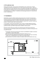
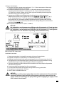
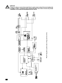
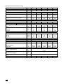
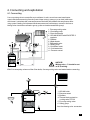
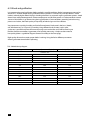
INSTRUCTION MANUAL
& SERVICE MANUAL
ORLAN SUPER 18-80 kW
Orlan
ISO 14001
ISO 9001
CE
Contents
1. Boiler’s use . . . . . . . . . . . . . . . . . . . . . . . . . . . . . . . . . . . . . . . . . . . . . . . . . . . . . . . . . . . . . . . . . . . . . . . . . . . . . . . . . . . . . . . . . . . . . . . . . . 3
2. Procedure rule . . . . . . . . . . . . . . . . . . . . . . . . . . . . . . . . . . . . . . . . . . . . . . . . . . . . . . . . . . . . . . . . . . . . . . . . . . . . . . . . . . . . . . . . . . . . . . 4
3. Installation . . . . . . . . . . . . . . . . . . . . . . . . . . . . . . . . . . . . . . . . . . . . . . . . . . . . . . . . . . . . . . . . . . . . . . . . . . . . . . . . . . . . . . . . . . . . . . . . . . 4
3.1. Diagram of chimney choice according to the DIN 4705 4 norm . . . . . . . . . . . . . . . . . . . . . . . . . . . . . . 5
4. Description of CONTROL SYSTEM . . . . . . . . . . . . . . . . . . . . . . . . . . . . . . . . . . . . . . . . . . . . . . . . . . . . . . . . . . . . . . . . . . . . . . . . . . 6
4.1. Front panel of EKOSTER 2 regulator . . . . . . . . . . . . . . . . . . . . . . . . . . . . . . . . . . . . . . . . . . . . . . . . . . . . . . . . . . . 6
4.2. Technical data of EKOSTER2 regulator - type 3.1 . . . . . . . . . . . . . . . . . . . . . . . . . . . . . . . . . . . . . . . . . . . . . 6
4.3. Functions of EKOSTER 2 regulator . . . . . . . . . . . . . . . . . . . . . . . . . . . . . . . . . . . . . . . . . . . . . . . . . . . . . . . . . . . . 7
5. Technical data of a boiler . . . . . . . . . . . . . . . . . . . . . . . . . . . . . . . . . . . . . . . . . . . . . . . . . . . . . . . . . . . . . . . . . . . . . . . . . . . . . . . . . . 11
6. Connecting and exploitation . . . . . . . . . . . . . . . . . . . . . . . . . . . . . . . . . . . . . . . . . . . . . . . . . . . . . . . . . . . . . . . . . . . . . . . . . . . . . . 13
6.1. Connecting . . . . . . . . . . . . . . . . . . . . . . . . . . . . . . . . . . . . . . . . . . . . . . . . . . . . . . . . . . . . . . . . . . . . . . . . . . . . . . . . . . . 13
6.2. Wood and gasification . . . . . . . . . . . . . . . . . . . . . . . . . . . . . . . . . . . . . . . . . . . . . . . . . . . . . . . . . . . . . . . . . . . . . . . 14
6.3. Accumulation . . . . . . . . . . . . . . . . . . . . . . . . . . . . . . . . . . . . . . . . . . . . . . . . . . . . . . . . . . . . . . . . . . . . . . . . . . . . . . . . . 15
6.4. Starting . . . . . . . . . . . . . . . . . . . . . . . . . . . . . . . . . . . . . . . . . . . . . . . . . . . . . . . . . . . . . . . . . . . . . . . . . . . . . . . . . . . . . . . 16
6.5. Burning up . . . . . . . . . . . . . . . . . . . . . . . . . . . . . . . . . . . . . . . . . . . . . . . . . . . . . . . . . . . . . . . . . . . . . . . . . . . . . . . . . . . . 16
6.6. Fuel loading . . . . . . . . . . . . . . . . . . . . . . . . . . . . . . . . . . . . . . . . . . . . . . . . . . . . . . . . . . . . . . . . . . . . . . . . . . . . . . . . . . 16
6.7. Boiler’s putting out . . . . . . . . . . . . . . . . . . . . . . . . . . . . . . . . . . . . . . . . . . . . . . . . . . . . . . . . . . . . . . . . . . . . . . . . . . . 17
6.8. Right boiler’s temperature assuring . . . . . . . . . . . . . . . . . . . . . . . . . . . . . . . . . . . . . . . . . . . . . . . . . . . . . . . . . .17
6.9. Power failure and pump’s breakdown . . . . . . . . . . . . . . . . . . . . . . . . . . . . . . . . . . . . . . . . . . . . . . . . . . . . . . . 17
7. Conservation . . . . . . . . . . . . . . . . . . . . . . . . . . . . . . . . . . . . . . . . . . . . . . . . . . . . . . . . . . . . . . . . . . . . . . . . . . . . . . . . . . . . . . . . . . . . . . . 18
7.1. Boiler’s conservation . . . . . . . . . . . . . . . . . . . . . . . . . . . . . . . . . . . . . . . . . . . . . . . . . . . . . . . . . . . . . . . . . . . . . . . . . . 18
7.2. Fan’s conservation . . . . . . . . . . . . . . . . . . . . . . . . . . . . . . . . . . . . . . . . . . . . . . . . . . . . . . . . . . . . . . . . . . . . . . . . . . . . 18
7.3. Boiler’s cleaning . . . . . . . . . . . . . . . . . . . . . . . . . . . . . . . . . . . . . . . . . . . . . . . . . . . . . . . . . . . . . . . . . . . . . . . . . . . . . . 18
7.4. Leakproof securing . . . . . . . . . . . . . . . . . . . . . . . . . . . . . . . . . . . . . . . . . . . . . . . . . . . . . . . . . . . . . . . . . . . . . . . . . . . 19 7.5. After-heating season maintenance activities . . . . . . . . . . . . . . . . . . . . . . . . . . . . . . . . . . . . . . . . . . . . . . . . . 20
8. Faults caused by boiler’s wrong exploitation and their removing . . . . . . . . . . . . . . . . . . . . . . . . . . . . . . . . . . . . . . . . 21
9. Allowance for Orlan SUPER boilers . . . . . . . . . . . . . . . . . . . . . . . . . . . . . . . . . . . . . . . . . . . . . . . . . . . . . . . . . . . . . . . . . . . . . . . . 22
9.1. Cooling coil . . . . . . . . . . . . . . . . . . . . . . . . . . . . . . . . . . . . . . . . . . . . . . . . . . . . . . . . . . . . . . . . . . . . . . . . . . . . . . . . . . . 22
9.2. Cleaning devices mechanism . . . . . . . . . . . . . . . . . . . . . . . . . . . . . . . . . . . . . . . . . . . . . . . . . . . . . . . . . . . . . . . . 22
10. Utilizing 23
2
1. Boiler’s use
Orlanski’s gasification boiler ORLAN SUPER is designed to work with solid fuel like: logs of wood
with dimensions of the boiler chamber, wood dust, wood chips and waste forestry. Logs of
wood must have moisture content between 15-25% and max. length 5 cm shorter than loading
chamber depth depending on boiler size; wood log diameter should be 15-25 cm.
OTICE!
N
Using different than ordinary fuel doesn’t guarantee boiler’s right operating - as it
was featured in technical data and it can influence the boiler’s way of working and its
long-lasting.
OTICE!
N
Using different type of fuel that the main one is treated as wrong boiler’s using and its
effects can not be the reason for any complaint to the producer.
OTICE!
N
Wood boiler is equipped with a regulator which assures its working in right
temperature’s range and protects the boiler against its overheating by fan’s turning
on.
3
2. Procedure rule
Wood gasification boilers work in pirolitic wood distillation process. When the air is limited
wood changes into charcoal while burning up. In the same time wood gas appears, which next
relocates to burner’s nozzle and there it is burnt at the bottom of the boiler. Such method of wood
burning allows for its effective using as fuel. Orlan boilers are made for burning wood billets (use
minced wood only as an addition - it should be mixed with bigger wood parts as not to allow for
burner’s nozzle littering).
3. Installation
Wood boilers are to be installed according to the present norms and rules. The requirements
of norm PN 87/B 02411 according building of solid fuel boiler room and the norm PN 91/B 02414
according closed system boilers’ installation should be taken into account. These norms and
rules should be followed, however, caution is required as national rules in countries in which the
product is sold may replace above-mentioned norms.
In case of boiler assembly outside the Poland, rules and norms should be followed according
to solid fuel boiler assembly in countries in which the product is sold. Eko-Vimar Orlanski wood
gasification boilers type SUPER are adjusted for installation in closed systems.
Eko-Vimar Orlański company prescribes using chimney inputs which preserve against the
chimney permeating. The company doesn’t take responsibility in case of faults resulting from not
using chimney inputs.
1. Chimney flue should correspond to the parameters of „DIAGRAM OF CHIMNEY CHOOSING
ACCORDING TO THE DIN 4705 NORM”.
2. Boiler room should be large enough to enable boiler’s cleaning (>2,2 m).
3. The distance between the boiler and the partitions should enable right access for all of the
boiler’s parts - it shouldn’t be less than - look at “Orlan boiler placing”.
4. There shouldn’t be any cables nor electric installations which aren’t for boiler room using.
Pic.1 Orlan boiler placing.
4
Chimney sweep should approve smoke outlet before its connecting to a chimney flue.
According to the PN-EN 303-5 norm accumulation tank should be assembled together with wood
boiler. We choose about 55 l heating water for every 1 kW installed power for example Orlan 25
kW = 25 kW x 55l = 1375 l
3.1. Diagram of chimney choice according to DIN 4705 norm
Thrust needed [Pa]
Boiler’s power [kW]
Internal diameter of
chimney flue (mm)
Chimney height [m]
5
4. Description of CONTROL SYSTEM
4.1. Front panel of EKOSTER 2 regulator
STOP
PUMP’S OPERATION
FAN’S OPERATION
FIRING-UP MODE
BLOW-THROUGH - INTERNAL TIME
BLOW-THROUGH - OPERATING TIME
POWER SWITCH
Pic.2 Description of the regulator’s panel.
4.2. Technical data of EKOSTER2 regulator - type 3.1
1. Temperature range
-9 °C up to +99 °C
2. Temperature setting
+60 °C up to +80 °C (in the type 3.4: +60 °C up to +97 °C)
3. Temperature of the pump turning on
+65 °C (in the type 3.4: +65 °C up to +90 °C)
4. Blowdown regulation
5. Hysteresis (the difference turn on- turn off)
6. Maximum switching power
working time
0-90 seconds
stopover
1-15 minutes
possibility of full blowthrough turning off
P-0
From 2 up to 9 °C
fan
100 W
pump
100 W
7. Main supply voltage / Frequency
230 V AC, 50 Hz
8. Maximum power taking
275 VA
9. Fan regulating power in % x 10
(regulation range from 30-100 %)
10. Outside humidity
≤ 95 %
11. Protection rating
IP 40
6
12. Insulation class
I
13. Surrounding temperature
0 – 40 °C
14. Disconnecting type
full
15. Over current protection
2 x 1.25 A (fuse)
OTICE!
N
If the “Er” appears on the screen it means that temperature either raised over 99 °C, it
decreased below -9 °C or the sensor got damaged. To secure together the boiler and
installation up to the time of the sensor replacing pump should be continuously ON till
that time.
4.3. The functions of EKOSTER 2 regulator
Use
The microprocessor temperature regulator for central heating boiler is designed to control the air
blow in wood-fired boiler and to actuate circulating pump in central heating system
The regulator performs the following functions:
• maintaining the set temperature of boiler by controlling air blow,
• smooths start-up of a blower,
• setting the blower power (service mode),
• programmable boiler „blow-through”,
• automatic control switch-off after boiler burnout (extinguishes),
• blower interlocking when feeding the boiler,
• control of central heating circulating pump depending on its set operating temperature,
• „COMFORT SYSTEM”,
• protection against freezing or overheating of boiler,
• signalling of temperature sensor’s damage,
• regulating the brightness of display - increased during read out and change of regulator
settings,
• control panel connecting possibility,
• room thermostat cooperation,
• automatic turning off in case of wrong burning up in the boiler,
• EKOSTER CONTROL cooperation.
Regulator working description
After switching on, the regulator passes into
state signalled by switching on of
corresponding lamp. Operation commences after pressing
button or automatically
when boiler’s temperature rises above operating threshold - that is, difference between set boiler
temperature and factory-set temperature difference “dt”. Automatic transition into

state occurs 30 minutes after boiler temperature drops below operating threshold. CONTROL
receptacle is for connecting remote control.
Pushbuttons and  serve to change the settings. During normal operation, pressing them
causes display and change of set boiler temperature. Pressing and holding pressed causes
increase in speed of temperature setting change.
Pressing the
button causes:
• with temperature below operating threshold: switching on or switching off control, signalled
by
or
indicators respectively,
• with temperature above operating threshold: blower interlocking signalled by pulsation of
indicator, enabling feeding of fuel into the boiler. Automatic return to operation
pressing.
7
COMFORT SYSTEM facility
The COMFORT SYSTEM function built into the regulator prevents against stone deposition
between pump rotor and stator. The regulator automatically actuates the pump after the heating
season for about 30 seconds, every 14 days. Operation of the pump in this mode is signalled by
pulsation of PUMP indicator. The system begins to operate 1 minute after regulator’s switching
on. Actuation of the pump in automatic mode causes re-counting of the 14-day period from the
beginning.
Antifreeze and overheating protection system
When the temperature decreases below 4 °C regulator secures the installation against its freezing
by the pump’s turning on. Temperature’s rising to more than 90 °C (in the type 3.4: +97 °C)
causes the fan’s turning off and the pump’s turning on. The button
beating alarms of the
boiler’s overheating. In the case reasons for overheating should be found, eliminated and as it
follows boiler should be engaged again by the button
pressing. Pump is continuously
on in case of the temperature’s sensor breaking down.
Programming of blow-through
• Press
and hold for about 3 s until the OPERATING TIME
• set the blow-through time in seconds with pushbuttons ,  ,
,
• Press
• set the blow-through interval in minutes with pushbuttons ,  ,
• Press
.
indicator switches on,
If the temperature excees over the set one, regulator will turn the fan ON from time to time.
OTE!
N
- setting the blow-through time to „0” causes blow-through switching off,
- above temperature of 85 °C (in the type 3.4: +98 °C), blow-through is switched off to
prevent overheating of the boiler.
Remote control
Regulator is accommodated for the remote „EKOSTER CONTROL” connecting, which enables
to control and change current boiler’s temperature, preview of the pump connection and
START-STOP mode, in the same time sonic gauge alarms when the boiler’s temperature abruptly
increases to hazardous level. Remote control with 10 m wire doesn’t go as a standard set - they
are to be bought separately.
Service mode
It is for regulator’s settings changes. To work on the mode you should:
• Swtch off the power,
• Switch the power back and in the time of some regulator’s version displaying (for example
2.2) press the
button and hold it up to the moment of “HI” appearing on the screen.
Since the time screen alternately shows the symbol and value of regulation task.
With ,  buttons the value can be changed and
regulation settings.
8
button causes moving to the next
Settings in correct order:
• „HI”: hysteresis of boiler’s temperature regulation (2 °C - 9 °C), that is temperature’s decreasing
to the low enough to cause fan’s turning on.
• „Po”: temperature when the pump turns on (65 °C), after room thermostat’s connecting we
change regulation for below 65 °C (in the type 3.4: +65 °C up to +90 °C) till the time when
„rP” appears on a display - Ekoster on basis of the signal transmitted by the room regulator
will control with pump’s working on its own.
• „dt”: temperatures’ difference at the beginning of working, that is on what temerature’s
difference from the one set by regulator will turn into
or
(10 °C - 30 °C)
ex. dt = 20, temperature set = 70 °C after temperature’s decreasing to 50 °C (temperature
decreased of set „dt” parameter from boiler setted temperature) regulator holds on for 30
minutes to burn out the rest of the fuel, after the fan turns off signalling in the same time fuel
shortage with
diode.
• „ ┌ ┐”: max power of the blower in % (3:30 % - 10:100 %).
OTICE!
N
It is advisable to set the temperature difference dt=10, hysterezis =2 °C and regulator
temperature 80 °C oir the boiler cooperating with accumulation tank. (in the type 3.4:
It is advisable to set the temperature difference dt=10, hysterezis=2 °C and regulator
temperature 90 °C oir the boiler cooperating with accumulation tank.)
Pic.3 EKOSTER 2 back view.
Installation instructions
1.Temperature regulator is designed for operating with central heating boilers.
2.Regulator’s connection is to be done by an authorized person only.
3.Regulator should be placed in the room preventing against its warming to more than 40 °C.
4.The regulator must be safeguarded against spilling of water and against conditions causing
condensation of vapour (e.g. sudden changes in ambient’s temperature).
5.The device should be installed and operated in accordance with the principles of procedure
with electrical equipment.
6.Fuse burnout does not constitute basis for warranty repair.
7.It is recommended to check the regulator settings before starting up the boiler.
8.The regulator is protected with 1.25 A fuse.
9.Sensor is to be assembled with no oil.
OTICE!
N
Connecting up of the pump supply cables as well as replacement of fuse should be
done with regulator supply switched off (regulator supply plug removed from the
supply socket). Connecting up the pump with regulator supply plug in supply socket
forms electric shock hazard.
9
Pic.4 Regulator operation and wiring system scheme.
OTICE!
N
Pump live wires’ connections and fuse’s replacement should be made when the
regulator is OFF ( connecting plug should be taken out of the current slot). If the
condition is not made it may cause electric shock.
10
5. Technical data of a boiler
Main construction parameters’ listing
Power
Total height
Heating water outlet height
Heating water inlet height
Bleeder height
Chimney height
Width of a casing
Total length
Heating water outlet
Chimney diameter
Total width
Cooling coil connection height
Cooling coil outlet
Diameter of a flange
Cooling coil flange diameter
Blowdown connection diameter
kW
A - mm
B - mm
C - mm
D - mm
E - mm
G - mm
H - mm
I - mm
J - mm
K - mm
L - mm
M - mm
Q - cale
R - cale
S - cale
19
1220
1210
210
140
870
545
960
340
180
660
990
260
2”
3/4”
1/2”
25
1320
1300
230
140
960
600
1040
310
200
720
1100
270
2”
3/4”
1/2”
40
1570
1560
220
140
1210
600
1040
300
200
720
1330
260
2”
3/4”
1/2”
60
1540
1575
200
140
1160
740
1340
570
210
860
1310
370
2”
3/4”
1/2”
80
1540
1590
200
140
1170
740
1700
600
210
860
1300
330
2”
3/4”
1/2”
11
Main construction parameters’ listing
Power
Power range
Efficiency
Boiler class
Boiler weight
Water capacity
Loading/combustion chamber capacity
Charging hole Width/Length
Fuel combustion time
Billets’ length
Wood humidity
- recomended
Power range for every kind of fuel:
Billets
Fuel taking for power:
- nominal
- minimal
Max. working pressure
Min. return temperature
Hydraulic resistance (primary cycle)
- t = 20 K
- t = 10 K
Temperature regulator setting range
Electric protection range
Pressure/Frequency
Auxiliary power
Fumes features (at nominal power):
- fumes temerature
- fumes flow
Chimney draught required
Cooling water pressure required at the
influx to a heat exchanger
Cold water temperature in the heat exchanger
Advisable capacity of an accumulation tank
12
19
7-19
25
10-25
3
5
dm
l
dm3
l
mm
h
cm
%
55
55
85
85
225/380
75
75
120
120
260/432
50
50
kW
7-19
kg/h
kW
kW
%
40
16-40
91
5
60
24-60
80
32-80
3
3
93
93
185
185
260/432
7-12
50
15-25
180
180
310
310
285/580
205
205
465
465
285/580
75
100
10-25
16-40
24-60
32-80
6,8
3,9
8,2
5,7
10,1
7,9
3
60
15,1
11,9
19,8
15,8
1,2
4,0
1,4
4,3
1,7
4,9
1,6
4,8
V/Hz
W
50
50
1,6
4,9
60-97
IP 40
230/50
50
100
100
°C
kg/s
150-180
0,0066
150-180
0,0088
150-180
0,0144
150-180
0,0216
150-180
0,0272
3000-4000
4000-5000
3
bar
°C
mbar
mbar
°C
mbar
Pa
0,15-0,20
15-20
bar
2
°C
l
10
750-1500
1000-2000
2000-3000
6. Connecting and exploitation
6.1. Connecting
Four-way mixing valve is essential for any installation. It’s role is to mix hot water (contribution
water) with the one returning from the system. Water mixing is necessary as to avoid „cold return
of the water” and to keep the same temperature of the boiler. What follows the temperature of heating system’s feeding can be lowered to the temperature of satisfactionary warmth in the house.
Mixing valves should be used both in gravity system and with extorted flow (pump).
1. F
our-way mixing valve
2. C
irculating pump
3. Room thermostat
4. ORLAN BOILER with EKOSTER 2
regulator
5. R
adiator
6. W
ater heater
7. Differential valve
8. S
afety group
9. C
old water outlet
10. Cold water inlet
11. Pressure vessel
NOTICE!
Mixing valve „1” should be set
at 50 % mixing.
Pic.5 An exemplary scheme of the Orlan boiler, four-way mixing valve and water heater connecting.
1. ORLAN boiler
2. Pressure vessel
3. Radiator
4. Thermal drain protection cooling valve STS 20
5. Four-way mixing valve
6. Safety group
Pic.6 Overheating valve -connection
13
6.2. Wood and gasification
It is important that wood gasification boilers worked in specific conditions. Boiler’s temperature accounts for
above 80 °C. At lower temperatures gasification doesn’t procees in a correct way and what follows - wood
intake is relatively higher. Wood drying in a loading chamber is an essential stage in gasification process -wood
doesn’t have adequate temperature at lower temperatures and all of the process is inadequate. Main warmth
source in Orlan boilers is gas flame arising during gasification, if main conditions according correct burning
process aren’t taken, then both quality and quantity of released gas won’t be sufficient.
Very important are: quality, humidity and kind of burned wood. Hard wood is the best - (beech,
oak, hornbeam etc.) at 15 up to 25 % humidity. Using different kinds of wood, such as pine,
spruce etc. is possible but there will be more burning waste at the sides and it will be necessary to
load the chamber more often. Hygrometer is for humidity measuring - it helps to select wood at
best quality (there is a guideline diagram of wood’s humidity on the next page).
Right quality of wood warranties proper boiler’s working. Using the fuel at different parameters
doesn’t guarantee correct boiler’s operating.
Tab. 4 Wood density diagram
wood type
pine
larch
spruce
fir
oak
elm
ash
beech
hornbeam
alder
birch
maple
lime
14
density of just cut wood [kg/m3]
coniferous tree
700
760
740
1000
deciduous tree
1080
950
920
990
1080
690
650
870
730
density of dry wood [kg/m3]
480
600
430
450
710
680
750
730
830
530
650
660
530
Optimum humidity
Outside drying
- in months
Pic.7 Hygrometer - an appliance for humidity
measurement - in Eko-Vimar Orlański’s offer.
Wood humidity [%]
Tree’s chopping off
Pic.8 Wood humidity chart.
6.3. Accumulation
The best results in heating gives boiler’s connecting with an accumulation tank. Such installation
causes less wood using - even up to 40 %. Gasification process (if it runs in optimum way)
generates large gas quantity, heating system however is characteristic for large fluctuation
amplitude in warmth requirement scope. Gasification process is set only in certain way, heating
system fluctuaction change more often, room might get overheated or some extra gas can
get through the chimney. Accumulation system allows for gas storing in an accumulation
tank. Heating system is contributed by accumulation tanks for about 48 h (depending on
tanks’ capacity and thermal conditions - at about 50 l of water for 1 kW of power). If the boiler
cooperates with accumulation tank, its long lasting is lengthened.
1. Boiler with Ekoster 2 regulator
2. Thermoregulator
3. Accumulation tank
4. Electrical heater
5. Three-way mixing valve
6. Circulating pump
7. Programmable room thermostat
8. Heating system exit
9. Pressure vessel
10. Mixing valve of DHW
11. C
oil
12. Solar panel
13. Heating medium pump
14. Safety group
Pic.9 An exemplary scheme of connecting an accumulation system with one accumulation tank (with
build in DHW container, coil and a solar).
15
6.4. Starting
Before first boiler’s use there should be checked: leakproof of the threaded joints (whether there
isn’t any leak) installation water level, the parameters of boiler’s operating are to be set as well.
6.5. Burning up
The steps to be taken to burn up in the boiler:
1. Switch off the power.
2. Push the chimney flap (gas pass opened).
3. Place splinters and some bigger wood pieces to the boiler upper chamber.
4. Burn the paper and close the upper door.
5. Open the bottom door as to provide natural draught.
6. Wait for about 15÷20 min. for better wood burning.
7. Put that much of wood to get the right quantity of embers which will cover boiler’s bottom
(ca. 10 cm) (chopping of the wood in about 5 cm pieces at the first stage of burning up
accelerates embers’ producing).
8. Wait for 15÷20 minutes for the ember layer occurring.
9. Fill up the whole combustion chamber.
10. Close the upper and bottom door hermetically.
11. Pull the chimney flap and switch on the fan.
12. When the boiler reaches 60 °C fan will start working automatically.
ARNING!
W
It is forbidden to switch on the fan when the upper door is opened.
Important!
It is important to pay an attention on both depth of gasificat-ion chamber and
thickness of the upper door while chamber’s loading. If wood’s sizes aren’t adequate
to the elements mentioned above it may be difficult to close boiler’s door or load
the chamber with wood. You must not close the door by force - it may cause door’s
damage.
Important!
Wood storing for about a year ensures its right humidity (admissable humidity - 25 %
- look at TECHNICAL DATA section). Advisable humidity level (15 %) is to be obtained
after 2 years wood storing (look at the diagram no 7).
6.6. Fuel loading
If the boiler is chosen adequate to the place to be warmed up there is one loading for 8÷12 hours
needed. It is advisable however to control the boiler every 5÷7 hours. To control wood quantity
you should:
1. Switch off the boiler with the main switch.
2. Open the chimney flap.
3. Open the upper door and load the chamber if it’s necessary.
4. Close the door, chimney flap and switch on the boiler.
It is important not to let the fuel to get between combustion chamber and chimney flap as it
would obstruct chimney flap’s closing.
When loading (it is recommended to burn out the fuel up to embers) there is a need of taking
down ash deposited on the loading chamber’s sidewall.
16
NOTICE!
Lack of fuel is signalled with a red indicator
.
6.7. Boiler’s putting out
Boiler puts out in two ways: after turning off button pressing or after all of the wood burning out.
6.8. Optimum boiler’s temperature assuring
Right boiler’s temperature maintaining during its exploitation is very important. To assure correct
gasification process water temperature should be about 75 °C.
In the time of a large warmth need returning water’s temperature may lower. If returning water
is about 20 °C lower than contributing one, there is a risk of gasification chamber cooling and
it can result in boiler’s efficiency decreasing (gasification process may be limited). As a result pitch can deposit at the boiler’s sidewalls. To avoid such situation there should be „little water
circulation” build in the boiler. To build it in three or four way mixing valve should be installed at
the boiler’s outlet. It mixes hot water with returning one. By correct hot and cold water setting,
returning water is warm enough as not to let for temperature’s rapid decreasing in the gasification
chamber - then gasification process correctly. Temperature’s difference 15÷20 °C doesn’t cause
large charge of material of which boiler is made of and as a consequence it lengthen boiler’s
exploitation time.
6.9. Power failure and pump’s breakdown
There is a risk of power deficiency or pump’s breaking down during boiler’s exploitation. If it happens in winter time, fuel filling should be stopped. Boiler’s working with a chimney flap opened
is unacceptable. Boiler’s working with full chimney draught may cause its uncontrollable working
and as a consequence it can cause water’s boiling and boiler’s overheating. In case of extorted
circulation installation, current flow’s breakdown causes fan’s and pump’s turning off . The case
of wrong warmth passing on from the boiler to the heaters may cause water’s overheating. It’s
advisable to install an additional container such as water heater to avoid water’s overheating.
Its role is to assure min power taking from the boiler ex 5 kW for the 25 kW boiler. It protects the
boiler against its overheating.
OTICE!
N
To protect the boiler and its electric equipment against network’s voltage excees it’s
advisable to use some constant - voltage regulator (e.g. computer strip).
17
7. Conservation
7.1. Boiler’s conservation
Except for the elements described in „BOILER’S EXPLOITATION” preserving it is important that
the boiler was protected during its stagnation (summer time, householders’ absence). Boiler’s
interior, hest, exchanger, chimney flap should be cleaned through - it’s advisable to burn some
dry softwood (ex. spruce) in the boiler before its stopping over - it will burn out the waste
occuring during boiler’s exploitation. After boiler’s cleaning it should be left opened for aerating in the way you will avoid humidity condensation in the boiler.
OTICE!
N
It is advisable to control the boiler annually in order to prepare it well for the next
heating season.
7.2. Fan’s conservation
Fan is an essential boiler’s part. Keeping it in clean have a bearing on its longlasting. It’s advisable
to disassembly fan’s body from time to time and to clean it through (the waste deposited). Fan’s
blades can be cleaned with a soft bristle brush.
OTICE!
N
Boiler’s working with the bottom door opened is unacceptable because in such a
case the fan can get overheated.
7.3. Boiler’s cleaning
The ash arising while burning process go down to the ash pit via the nozzle. The ash pit should
be cleaned every 3-5 days. Gasification chamber should be cleaned out between next burning
up. Ash is to be cleaned out via the nozzle - watch out as not to damage the boiler’s bottom. For
cleaning there should be used original appliances (enclosed as standard equipment). During
gasification process pitch occurs. Its quantity depends on wood, its humidity and contributing
and returning water’s temperature. It’s advisable to clean out gasification chamber with a scraper
(once a month). Carbon deposit subsiding at the pipes causes diminish of the exchanger’s section
and in the same time decreasing of the heat exchange. As a result it effects the thrust decreasing
and obstructs in heat transmitting. In accordance to this the exchanger’s pipes should be cleaned
out every two weeks to assure their permeability. (In SUPER boiler they should be cleaned after
every fuel loading.)
Four steps to clean out the exchanger (except for the SUPER type)
1. Take off the boiler back upper casing.
2. Turn on the nuts with M13 - M17 spanners (depending on boiler type).
I mportant!
Before nuts turning on and turning off the thread should be preserved with a special
anti corrosion agent; do not turn on nuts with exertion.
3. Each of the pipes in the exchanger should be cleaned with a cleaning shield. They should be
cleaned precisely in the whole length - it is important to avoid soot’s gathering at the bottom
part of the exchanger’s pipe and its blocking. Clean the soot deposited at the back part of the
chamber.
I mportant!
As to avoid the soot sediment in lower part of an exchanger it is necessary to sweep
out the soot from the back part of the boiler chamber.
18
The Eko-Vimar Orlański advices using SADPAL - a catalyst for wood tar burning. It is to burn up
the wood tar all over the boiler, beginning with a burner, combustion chamber and a chimney.
All details according the SADPAL use are written on a packaging. The product is available in
Eko-Vimar Orlański offer.
7.4. Leakproof securing
Leakproof of the boiler is very important especially leakproof of the door, the exchanger and
chimney flap. Leakproof causes the fumes’ coming out of the boiler and most of all it can cause
uncontrolled burning which may cause boiler’s overheating. To ensure the exchanger’s door leakproof the insulation rope should be sealed with a graphite oil or some other machine oil at least
once a week. It soften the rope and causes its tight adjoining to the boiler.
After some time of boiler’s operating (1 season for example) the door rope could get flatted. To
assure right rope’s adjoining to the boiler’s door, door setting regulation is provided (regulation on
the hinge).
Hinge door setting:
a) take the door off
b) loosen the cap
c) turn the hinge 360°
d) turn a tap tight to block hinge’s
regulating screw.
OTICE!
N
Upper and down hinge should be
regulated in the same time.
blocking nut
Pic10. Cleaning elements.
- Only in STANDARD version
OTICE!
N
Chimney flue’s leakproof should be controlled and if such a need occurs - it should
be cleaned out. All of the threaded elements before their unscrewing should be
lubricated with grease. Door and hinges should be lubricated temporarily as well.
19
7.5. After-heating season maintenance activities
It is necessary to prepare boiler for upcoming heating season in order to assure trouble-free boiler usage.
It is recommended to commission boiler inspection to qualified serviceman of boiler distributor. This will
guarantee professional and skilled boiler preparation based on long-term experience of boiler producer.
ACITIVITY:
- thoroughly clean upper and bottom chamber from remaining ashes
- clean upper chamber’s all sides from tar with boiler tools as deposited tar creates layer of
insulation that decreases boiler efficiency
- remove fan cover and clean fan blades with brush or vacuum cleaner
- check and clean if necessary primary air if there’s a free flow of air by turning on the fan on cleaned boiler(air goes to upper chamber with two channels on the front left and right side of upper chamber; air
is blown with fan). Tar may deposit in these channels that obstruct proper amount of air supplied to upper
chamber.
- check and clean if necessary secondary air if there’s a free flow of air by turning on the fan on cleaned boiler
(air goes to nozzle via 2 pipes and is blown through holes in nozzle; air is blown with fan) Tar or ash may
deposit in these holes that obstruct proper amount of air supplied to nozzle.
- check cleanliness of heat exchanger’s pipes
- clean connecting flue pipe between boiler flue and chimney. Clean chimney as correct chimney draft is vital
for boiler running
- grease all threaded parts (hinges, door handle)
- grease door ropes ( this should be done every 3 weeks as flexible ropes protect boiler from smoking outside
to boiler room)
- prepare wood for upcoming heating season – use only wood with moisture content below 25%. Check
moisture content with moisture meter on split wood log into halves. Wood log should have length the same
as chamber depth (ex. Orlan 25 kW – 50 cm)
ATTENTION!!!
IT IS CRUCIAL FOR PROPER BOILER RUNNING TO HAVE PRIMARY AIR CHANNELS AND SECONDARY AIR PIPES
CLEANED AND FREE OF ANY ELEMENTS THAT MAY OBSTRUCT FLOW OF NECESSARY AIR TO UPPER CHAMBER
AND NOZZLE. OBSTRUCTED FLOW OR NOT ENOUGH OF IT MAY LEAD TO UNPROPER BOILER BURNING –
BOILER WOULD NOT BE ABLE TO REACH RECOMMENDED SET TEMP. OF 80-90 DEGREES WHICH IS NECESSARY
FOR GASIFICATION BOILER TO FULLY UTILIZE ENERGY IN WOOD. AT LOW TEMP. AND WITH LONG RUNNING
ON LOW TEMP. BOILER CREATES EXTENSIVELY TAR THAT CLOGS PRIMARY AND SECONDARY AIR CHANNELS.
BOILER WITH NOT ENOUGH AMOUNT OF AIR SMOKES EXTENSIVELY CREATING ACIDS CONTAINED IN WOOD
THAT CAN LEAD TO INNER BOILER PLATE THINNING.
ATTENTION!!!
INNER BOILER PLATE THINNING MAY ALSO BE RESULT OF BURNING WOOD WITH MOISTURE CONTENT
ABOVE 25%.
20
8. Faults caused by boiler’s wrong exploitation
and their removing
Problem
boiler doesn’t
reach the
temperature
needed
smoke out of the
cleaning cover
smoke coming
out while loading
(little smoke is
acceptable)
smoke out of the
boiler’s door
regulator doesn’t
work
fan out of order
21
Cause
Remedy suggested
faulty burning up
check „Burning up”
to moist wood
humidity control - use wood at right parameters
primary air conduit choked
call service - facility out of the warranty
secondary air conduit choked
call service - facility out of the warranty
smoke tube of heat exchanger
choked
clean with a cleaning shield or call service- facility
out of the warranty
wrong regulation of the air and
wood gas
call service - facility out of the warranty
nozzle damaged
replacement - out of the warranty
fan’s gasket damaged
replacement - out of the warranty
fan damaged
replacement - out of the warranty
leak on a seal rope
door regulation or call service – out of the warranty
seal rope worn
rope’s replacement - out of the warranty
cover warped - overheating
cover’s replacing or call service- out f the warranty
intensive - Heavy wind blows the
fumes into the chimney
consider the montage of chimney flue succouring
elements, for instant the „Rotowent” ones
wrong chimney parameters
consult a chimney sweep, the need of new
chimney flue building
leak on a seal rope
door regulation
(according to the 7.4. description)
seal rope worn
rope’s replacement or call service
- out of the warranty
door damaged
door’s replacement
power shortage
check the installation’s protection
fuse damaged
fuse’s replacement
live wire conduit damaged
connection and wire’s inspection
temperature sensor damaged
call service
regulator damaged
call service
thermal protection worked
check „boiler’s overheating” description
no power in regulator
check „power shortage in regulator”
fan damaged
call service - fan’s replacement
regulator damaged
call service
fan blocked
inspect and clean the fan
Problem
fan’s loud working
poor fan’s working
detonation in the
boiler
Cause
Remedy suggested
bearings damaged
call service - fan’s replacement
condenser damaged
call service - condenser’s replacement
fan montaging clips loosened
checking, turn the clips tight
fan’s blades unclean
checking, cleaning
unneeded unit in fan’s cover
checking, cleaning
fan’s blades unclean
checking, cleaning
fan’s cover with a pitch on the fan’s
cover
call Service- out of the warranty
wrong burning up
look „Burning up”
chimney draught to low (below
10 Pa)
chimney rebuilding. Use WKO exhaust fan
chimney draught to intensive (over
20 Pa)
use exhaust regulator
to tiny and to dry wood (humidity
over 15 %)
mix with larger humidity fuel as to increase
humidity level (in about 15-25 %)
furnace flue of the exchanger
uncleaned
clean the exchanger or call service- out of the
warranty
9. Allowance for Orlan SUPER boilers
Wood boilers in version SUPER are equipped with a cooling coil (preserving against overheating)
and mechanical cleaning devices.
9.1. Cooling coil
In connection with thermostatic cooling valve cooling coil’s function is the boiler’s overheating
protection. We connect a cooling coil with thermostatic valve to the cold water installation (ex.
STS 20 Watts). Cooling coil outlet is to be directed into plughole installation.
9.2. Cleaning devices mechanism
Mechanical cleaning devices allow for heat exchangers
keeping in clean. Cleaning elements are made as
economizers placed in a heating pipe. They are moved
with a handle placed out of a boiler.
OTICE!
N
As not to let cleaning devices and
furnace flue to get dirty with burning
remnants it is important to use cleaning
22
Warranty notice
Small cracks on the surface of the insulation board of ashes on the surface firing channel (profile "U") are
normal and does not affect operation and the lifetime of the parts. Combustion channel is consumable
and the lifetime of these is influenced by the quality and duration of combustion operation (humidity of
the wood must be below 20%)
. The boiler room, If it’s humid constantly firebrick absorbs the vapor which when boiler fired expands and
evaporate and cracks the firebrick.
10. Utilizing
The appliance is approved according to the European Directive 2002/96/EC
in the matter of electrical and electronic devices’ waste (WEEE). Ensuring
right its scrapping you help to
protect the environment.
Wrong utilization of the appliance may cause negative influence on the environment. To prevent it - make sure
that you utilize the boiler in a proper way.
The symbol placed either on the device or in the documents enclosed means that the product isn’t classified as
a household waste.
The appliance should be taken to an authorized collection point in the matter of electric and electronic
components recycling.
The wood boiler should be scrapped according to local regulations according waste utilization.
More informations according utilization, scrapping and recycling you can get in the local city hall, in civic waste
utilization company or in the place of he machine buying.
23
CRANP-KOVO s.r.o.
790 70 Javornik, Miru 371
CZECH REPUBLIC
T +420 584 492 808
F +420 584 492 888
E [email protected]
www.orlanski.cz