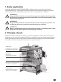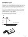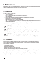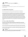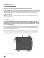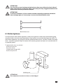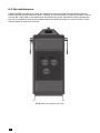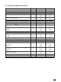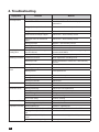
1
INSTRUCTION MANUAL & SERVICE MANUAL ORLAN SUPER 96 kW ORLAN SUPER 130 kW ISO 14001 ISO 9001 USER MANUAL FOR BATCH FED INDEPENDENT WOOD LOG FIRED BOILERS SUPPLEMENTARY INSTALLATION INSTRUCTIONS FOR THE UK MARKET TO BE READ IN CONJUNCTION WITH THOSE IN THE INSTRUCTION BOOKLET READ THE INSTRUCTION BOOKLET AND THESE SUPPLEMENTARY INSTRUCTIONS CAREFULLY BEFORE INSTALLATION These instructions together with those in the instruction booklet cover the basic principles to ensure the satisfactory installation of the boiler, although detail may need slight modification to suit particular local site conditions. In all cases the installation must comply with current Building Regulations, Local Authority Byelaws and other specifications or regulations as they affect the installation of the boiler. If any guidance contained within this manual contradicts advice given in the main manufacturer’s instruction manual then the most stringent advice must apply. It should be noted that the Building Regulations requirements may be met by adopting the relevant recommendations given in British Standards BS 8303, BS EN 15287-1:2007 as an alternative means to achieve an equivalent level of performance to that obtained following the guidance given in Approved Document J. Please note that it is a legal requirement under England and Wales Building Regulations that the installation of the boiler is either carried out under Local Authority Building Control approval or is installed by a Competent Person registered with a Government approved Competent Persons Scheme. HETAS Ltd operate such a Scheme and a listing of their Registered Competent Persons can be found on their website at www.hetas.co.uk. CO Alarms:Building regulations require that whenever a new or replacement fixed solid fuel or wood/biomass appliance is installed in a dwelling a carbon monoxide alarm must be fitted in the same room as the appliance. Further guidance on the installation of the carbon monoxide alarm is available in BS EN 50292:2002 and from the alarm manufacturer’s instructions. Provision of an alarm must not be considered a substitute for either installing the appliance correctly or ensuring regular servicing and maintenance of the appliance and chimney system. HEALTH AND SAFETY PRECAUTIONS Special care must be taken when installing the boiler such that the requirements of the Health and Safety at Work Act (1974) are met. Handling Adequate facilities must be available for loading, unloading and site handling. Fire Cement Some types of fire cement are caustic and should not be allowed to come into contact with the skin. In case of contact wash immediately with plenty of water. Asbestos Page 1 of 7 This boiler contains no asbestos. If there is a possibility of disturbing any asbestos in the course of installation then please seek specialist guidance and use appropriate protective equipment. Metal Parts When installing or servicing this boiler care should be taken to avoid the possibility of personal injury. BOILER PERFORMANCE Refer to the main instruction manual for details of the boiler’s performance. PREPARATORY WORK AND SAFETY CHECKS IMPORTANT WARNING This boiler must not be installed into a chimney that serves any other heating appliance. There must not be an extractor fan fitted in the same room as the boiler as this can cause the boiler to emit fumes into the room. Chimney In order for the boiler to perform satisfactorily the chimney height must be sufficient to ensure an adequate draught of approximately 15 Pa so as to clear the products of combustion and prevent smoke problems into the room. NOTE: A chimney height of not less than 4.5 metres measured vertically from the outlet of the boiler to the top of the chimney should be satisfactory. Alternatively the calculation procedure given in EN 13384-1 may be used as the basis for deciding whether a particular chimney design will provide sufficient draught. The outlet from the chimney should be above the roof of the building in accordance with the provisions of Building Regulations Approved Document J. Because the boiler runs at high efficiencies, the temperature of the flue gases is at times lower than conventional solid fuel appliances. Although it is not classed as a condensing appliance, the low flue gas temperature results in condensation occurring within the flue. Any chimney flue system must therefore be able to withstand the effects of condensate and operate under wet conditions (designation letter W). In addition it should be soot fire resistant and able to withstand the corrosive effects of flue products generated by solid fuels (designation G and 3 respectively). If installation is into an existing masonry chimney then it will require re-lining with a liner meeting the specification described above. Existing concrete or clay lined chimneys are not suitable for this boiler and must be lined as described above. All installations must be in accordance with Building Regulations Approved Document J. Any existing chimney must be clear of obstruction and have been swept clean immediately before installation of the lining system. Where the chimney is believed to have previously served an open fire installation it is possible that the higher flue gas temperature from a closed appliance may loosen deposits that were previously firmly adhered, with the consequent risk of flue blockage. It is therefore recommended that the chimney be swept a second time within a month of regular use after installation. If there is no existing chimney then any new system must be to the designation described above and in accordance with Building Regulations Approved Document J. A single wall metal fluepipe is suitable for connecting the boiler to the chimney but is not suitable for use as the complete chimney. The chimney and connecting fluepipe must have a minimum diameter of 150 mm and its dimension should be not less than the size of the outlet socket of the boiler. Any bend in the chimney or connecting fluepipe should not exceed 45. 90 bends should not be used. Combustible material should not be located where the heat dissipating through the walls of fireplaces or flues could ignite it. Therefore when installing the boiler in the presence of combustible materials due account Page 2 of 7 must be taken of the guidance on the separation of combustible material given in Building Regulations Approved Document J and also in these boiler instructions. If it is found that there is excessive draught in the chimney then a draught stabiliser should be fitted in the chimney above the chimney above the flue pipe connection. Fitting of a draught stabiliser will affect the requirement for the permanent air supply into the room in which the boiler is fitted in accordance with Approved Document J (see also combustion air supply). Adequate provision e.g. easily accessible soot door or doors must be provided for sweeping the chimney and connecting fluepipe. Hearth The hearth should be able to accommodate the weight of the boiler and its chimney if the chimney is not independently supported. The weight of the boiler is indicated in the brochure. The boiler should preferably be installed on a non-combustible hearth of a size and construction that is in accordance with the provisions of the current Building Regulations Approved Document J. The clearance distances to combustible material beneath, surrounding or upon the hearth and walls adjacent to the hearth should comply with the guidance on the separation of combustible material given in Building Regulations Approved Document J and also in these boiler instructions. If the boiler is to be installed on a combustible floor surface, it must be covered with a non-combustible material at least 12mm thick, in accordance with Building Regulations Approved Document J, to a distance of 30 cm in front of the boiler and 15 cm to each side measuring from the door of the combustion chamber. Combustion air supply In order for the boiler to perform efficiently and safely there must be an adequate air supply into the room in which the boiler is installed to provide combustion air. The provision of air supply to the boiler must be in accordance with current Building Regulations Approved Document J. An opening window is not appropriate for this purpose. Connection to chimney All boilers have a flue gas connector that allows connection to either a masonry chimney or a prefabricated factory made insulated metal chimney in accordance with the instructions. This connection should never be reduced in diameter to lower than that of the flue gas connector of the boiler. In some cases it may be necessary to fit an adapter in the connection pipe to increase the diameter to the required minimum diameter of 150 mm for burning wood fuel in accordance with UK regulations. Any connections should be made gastight and sealed with a suitable sealing agent such as fire cement. Connection to the central heating system The boilers may be installed on either open vented or sealed fully pumped systems. The water system must be properly vented and a double-feed indirect cylinder to the current specification in issue BS 1566 Part 1 for double indirect cylinders is necessary where there is a combined hot water and central heating system. During installation caution must be made on the need for a gravity heat-leak radiator or towel rail to dissipate heat when the pump is off and the minimum load for this function. The central heating system must be in accordance with BS EN 14336:2004: Heating Systems in Buildings. Installation and commissioning of water based heating systems. BS EN 12828: 2003; Heating Systems in Buildings. Design of water based heating systems. BS EN 12831: 2003; Heating Systems in Buildings. Method for calculation of the design heat load and BS 6880:1988 Parts 1 to 3, Code of Practice for low temperature hot water heating systems of output greater than 45kW where appropriate. Electrical connections Page 3 of 7 The installation of any electrical services during the installation of this boiler and the associated heating system must be carried out by a registered competent electrician and in accordance with the requirements of the latest issue of BS 7671. Commissioning and handover Ensure all parts are fitted in accordance with the instructions. On completion of the installation allow a suitable period of time for any fire cement and mortar to dry out, before lighting the boiler. Once the boiler is under fire check all seals for soundness and that the boiler and water system are operating correctly. Ensure that the flue is functioning correctly and that all products of combustion are vented safely to atmosphere via the chimney terminal. On completion of the installation and commissioning ensure that the operating instructions for the boiler are left with the customer. Ensure to advise the customer on the correct use of the appliance and warn them to use only the recommended fuel for the boiler. Advise the user what to do should smoke or fumes be emitted from the boiler. The customer should be advised about restricting access to the boiler by children, aged and/or infirm people. Page 4 of 7 USER MANUAL FOR BATCH FED INDEPENDENT WOOD LOG FIRED BOILERS SUPPLEMENTARY OPERATING INSTRUCTIONS FOR THE UK MARKET TO BE READ IN CONJUNCTION WITH THOSE IN THE INSTRUCTION BOOKLET READ THE INSTRUCTION BOOK AND THESE INSTRUCTIONS CAREFULLY BEFORE USING THE BOILER WARNING NOTE Properly installed, operated and maintained this stove will not emit fumes into the dwelling. Occasional fumes from de-ashing and re-fuelling may occur. However, persistent fume emission is potentially dangerous and must not be tolerated. If fume emission does persist, then the following immediate action should be taken: (a) Open doors and windows to ventilate the room and then leave the premises. (b) Let the fire go out. (c) Check for flue or chimney blockage and clean if required (d) Do not attempt to relight the fire until the cause of the fume emission has been identified and corrected. If necessary seek expert advice. The most common cause of fume emission is flueway or chimney blockage. For your own safety these must be kept clean at all times. IMPORTANT NOTES General Before lighting the boiler check with the installer that the installation work and commissioning checks described above have been carried out correctly and that the chimney has been swept clean, is sound and free from any obstructions. As part of the boilers’ commissioning and handover the installer should have shown you how to operate the boiler correctly. Do not light the boiler if there is a possibility that any part of the heating system may be frozen Please make sure the ash-pit door and the hopper lid/charging door are firmly closed at all times whilst the boiler is in operation. CO Alarm Your installer should have fitted a CO alarm in the same room as the appliance. If the alarm sounds unexpectedly, follow the instructions given under “Warning Note” above. Boiler Access Access to the boiler should be restricted for children, aged and/or infirm persons by way of a lockable door to the room in which the boiler is installed. Chimney cleaning The chimney should be swept at least twice a year. It is important that the flue connection and chimney are swept prior to lighting up after a prolonged shutdown period. Where the chimney is believed to have a served Page 5 of 7 an open fire installation it is possible that the higher flue gas temperature from a closed appliance may loosen deposits that were previously firmly adhered, with the consequent risk of flue blockage. It is therefore recommended that the chimney be swept a second time within a month of regular use after installation. In situations where it is not possible to sweep through the boiler the installer will have provided alternative means, such as a soot door. After sweeping the chimney the boiler flue outlet and the flue pipe connecting the boiler to the chimney must be cleaned with a flue brush. Periods of Prolonged Non-Use If the boiler is to be left unused for a prolonged period of time then it should be given a thorough clean to remove ash and unburned fuel residues. Empty the hopper of unburned fuel. To enable a good flow of air through the appliance to reduce condensation and to avoid door seals becoming stuck and subsequently damaged, leave the filling hatch and combustion chamber doors slightly ajar. These actions will reduce the possibility of unnecessary damage and corrosion. Extractor fan There must not be an extractor fan fitted in the same room as the boiler as this can cause the boiler to emit smoke and fumes into the room Aerosol sprays Do not use an aerosol spray on or near the boiler when it is alight. Use of operating tools Always use the operating tools provided when handling parts likely to be hot when the boiler is in use. Chimney Fires If the chimney is thoroughly and regularly swept, chimney fires should not occur. However, if a chimney fire does occur turn off the boiler immediately and isolate the mains electricity supply, and tightly close the doors of the boiler. This should cause the chimney fire to go out. If the chimney fire does not go out when the above action is taken then the fire brigade should be called immediately. Do not relight the boiler until the chimney and flue ways have been cleaned and examined by a professional. Permanent air vent The boiler requires a permanent and adequate air supply in order for it to operate safely and efficiently. In accordance with current Building Regulations the installer may have fitted a permanent air supply vent into the room in which the boiler is installed to provide combustion air. This air vent should not under any circumstances be shut off or sealed. USER OPERATING INSTRUCTIONS Please read the important notices given above before referring to the main instruction book for detailed operating instructions. Frequency of cleaning ash and residues from combustion chamber and ash-box The owner is required to regularly carry out this cleaning operation and the frequency will depend on the heating load. When first put to use the boiler should be checked on a daily basis and experience will show how often this will eventually be required. Remember also that during the main heating season the cleaning interval will shorten as the load on the boiler will be higher. Recommended fuels The boiler is designed to burn wood logs only as detailed in the main instruction book. Under no circumstances should you attempt to burn any other type of fuel. Page 6 of 7 General Maintenance It is important that any glass or other decorative surfaces are kept clean using the appropriate cleaning materials and techniques as to not damage the internal or external finishes of the boiler. Spare Parts For more information on obtaining spare parts, please revert to the specific page of the manufacturer’s original instruction manual or contact details provided. HETAS Ltd Approval This appliance has obtained HETAS Ltd approval for burning wood logs only as specified in the main instruction manual. Approval does not cover the use of other fuels either alone or mixed with the recommended fuel, nor does it cover instructions for the use of other fuels. Page 7 of 7 INSTRUCTION MANUAL Content 1. Boiler application . . . . . . . . . . . . . . . . . . . . . . . . . . . . . . . . . . . . . . . . . . . . . . . . . . . . . . . . . . . . . . . . 3 2. Principle of work . . . . . . . . . . . . . . . . . . . . . . . . . . . . . . . . . . . . . . . . . . . . . . . . . . . . . . . . . . . . . . . . 3 3. Description of the controller . . . . . . . . . . . . . . . . . . . . . . . . . . . . . . . . . . . . . . . . . . . . . . . . . . . . . . 4 3.1. Front panel of EKOSTER 2 . . . . . . . . . . . . . . . . . . . . . . . . . . . . . . . . . . . . . . . . . . . . . . 4 3.2. Main functions of EKOSTER 2 . . . . . . . . . . . . . . . . . . . . . . . . . . . . . . . . . . . . . . . . . . . 4 4. Gasification process . . . . . . . . . . . . . . . . . . . . . . . . . . . . . . . . . . . . . . . . . . . . . . . . . . . . . . . . . . . . . 7 5. Boiler start-up . . . . . . . . . . . . . . . . . . . . . . . . . . . . . . . . . . . . . . . . . . . . . . . . . . . . . . . . . . . . . . . . . . . 8 5.1. Lightning up . . . . . . . . . . . . . . . . . . . . . . . . . . . . . . . . . . . . . . . . . . . . . . . . . . . . . . . . . . . 8 5.2. Fuel stoking . . . . . . . . . . . . . . . . . . . . . . . . . . . . . . . . . . . . . . . . . . . . . . . . . . . . . . . . . . . 8 5.3. Boiler turning off . . . . . . . . . . . . . . . . . . . . . . . . . . . . . . . . . . . . . . . . . . . . . . . . . . . . . . 9 5.4. Optimal boiler’s temperature . . . . . . . . . . . . . . . . . . . . . . . . . . . . . . . . . . . . . . . . . . . . 9 5.5. Power outage and pump failure . . . . . . . . . . . . . . . . . . . . . . . . . . . . . . . . . . . . . . . . . 9 6. Maintenance . . . . . . . . . . . . . . . . . . . . . . . . . . . . . . . . . . . . . . . . . . . . . . . . . . . . . . . . . . . . . . . . . . . 10 6.1. Boiler maintenance . . . . . . . . . . . . . . . . . . . . . . . . . . . . . . . . . . . . . . . . . . . . . . . . . . . 10 6.2. Boiler cleaning . . . . . . . . . . . . . . . . . . . . . . . . . . . . . . . . . . . . . . . . . . . . . . . . . . . . . . . 10 6.3. Boiler tightness . . . . . . . . . . . . . . . . . . . . . . . . . . . . . . . . . . . . . . . . . . . . . . . . . . . . . . . 11 6.4. Fan maintenance . . . . . . . . . . . . . . . . . . . . . . . . . . . . . . . . . . . . . . . . . . . . . . . . . . . . . 12 2 1. Boiler application Orlanski’s gasification boiler ORLAN SUPER is designed to burn wood. As a main fuel it is recommended to use wood logs with moisture content 15-25% and max. length 5 cm shorter than loading chamber depth depending on boiler size; wood log diameter: 15-25 cm. ATTENTION! Using fuel different than the recommended not guarantees optimum boiler operation and achieving parameters featured in technical data. It can also affect durability of the boiler and its components. ATTENTION! Using fuel different than the recommended is treated as wrong boiler operation and resultant performance irregularities cannot be reason for complaint. ATTENTION! Boiler is equipped with controller that enables to operate in right temperature’s range and protects the boiler against overheating by fan activation. 2. Principle of work Gasification boilers utilize process of dry, pyrolitic wood distillation. During wood burning with limited amount of air, wood changes into charcoal. Gasification process creates large amount of wood gases which are directed to ceramic nozzle and burned in flame form in bottom chamber. This method of wood burning efficiently make use of wood as a fuel. STAGE FOUR Exhaust gases at temp. 160°C are emitted through boiler flue STAGE ONE Wood drying and degassing temp. 450°C STAGE TWO Burning of mixed wood gases with secondary air at temp. 560°C STAGE THREE Burning up the flame and heat emission at temp. of 1200°C 3 3. Description of the controller 3.1. Front panel of EKOSTER 2 STOP STOP PUMP’S OPERATION FAN’S OPERATION START FIRING-UP MODE BLOW-THROUGH - INTERNAL TIME BLOW-THROUGH - OPERATING TIME POWER SWITCH Pic.1 Controller’s description. 3.2. Main functions of EKOSTER 2 Application The microprocessor temperature’s controller for central heating boiler is designed to control the air blow in wood-fired boiler and to actuate circulating pump in central heating systems. Controller performs the following functions: • maintaining set temperature of boiler by controlling air blow, • smooth start-up of a blower, • setting the blower power (service mode), • programmable boiler „blow-through”, • automatic control switch-off after boiler burnout (extinguish), • blower interlocking when feeding the boiler, • control of central heating circulating pump depending on its set operating temperature, • „COMFORT SYSTEM” mode, • protection against freezing or overheating of boiler, • signalling of temperature sensor’s damage, • regulating the brightness of display - increased during readout and change of regulator settings, • room thermostat cooperation, • automatic turning off in case of wrong burning up in the boiler, • EKOSTER CONTROL co-operation. 4 Operation description After switching on, controller is in , which is signaled by adequate diode. Operation starts after pressing or automatically, when boiler’s temperature increases above operating threshold – temperature difference between set temperature and DT parameter set in the service menu. Status is automatically activated after 30 minutes since temperature decrease below operating threshold. CONTROL socket which is located at the back panel of the controller is for connection of remote control EKOSTER CONTROL. Buttons and are for setting's changes. During boiler operation, pressing or causes possibility to change desired boiler’s temperature. Pressing and withholding button causes increase of speed of temperature changing. Pressing button causes: • temperature below operating threshold:turning on/off of the controller signaled with diodes or , • at temperature above operating threshold:fan operation blockade signaled by blinking , diode, which makes possible to stoke the boiler. Return to automatic operation after pressing button. TTENTION! A Displaying „Er” on the controller informs about temperature increase above 99 °C, below -9 °C or boiler sensor damage. To secure the boiler till sensor replacement, pump will be automatically activated. COMFORT SYSTEM COMFORT SYSTEM function in controller prevents pump’s rotor from stone deposition. Controller automatically activates pump after heating season for 30 seconds every 14 days. Pump operation in this mode is signaled with flashing PUMP diode. Function activates after 1 minute since controller’s activation. Pump activation in this mode causes that 14 days period is counted from the beginning. Freezing and overheating function Controller enables to turn on circulation pump In case if temperature drops to 4 °C or lower. Exceeding 97°C causes fan to turn off and circulation pump activation. Boiler overheating is signaled with flashing diode. In such a case it is recommended to determine cause of overheating, eliminate and turn on the boiler pressing button. Pump is activated permanently In case of boiler sensor damage. Blow-through • Press and hold for 3 s till diode starts blinking, • Buttons , are for blow-through time setting in seconds, • Press dtill diode starts blinking, • With buttons , set blow- through pause in minutes, • Press . From now on controller at temperatures higher than set one will activate blow-through. 5 TTENTION! A - Setting blow-through on „0” will deactivate blow-through,, - Above 98 °C blow-through is turned off not to overheat the boiler. Remote control Controller is adjusted to install remote control „EKOSTER CONTROL” that enables to control and change the boiler’s temperature, displays of pump condition and mode START-STOP, at the same time remote control can activate alarm in case of temperature sudden increase to alarming level. Remote control with 10 or 15 meters cable is an accessory appliance. Service mode Service mode is for settings changes. To enter service mode: • turn off controller, • turn on and during controller’s software displaying (ex. 3.4) press and hold parameter “HI” will display. button until Controller displays in turn symbol and its value. , buttons enables to change current parameter value and button is for moving on to next parameter: Parameter order: • „HI” temperature’s hysteresis (setting range: 2 – 9 °C) how much temperature must fall from set temperature to turn the fan on. • „Po” temperature of pump activation - pre-set 65°C (setting range: 65-90°C), after room thermostat connection, change temperature below 65°C, till „rP” parameter appears on display– Ekoster based on signal from room thermostat will automatically control pump’s operation. • „DT” temperature’s difference from operation threshold: at what temperature’s difference controller will enter or status (setting range: 10-30°C) for example DT=20, set temperature = 70°C, after falling below 50°C ( temperature decreased below DT parameter) controller will wait 30 minutes and will turn off fan signaling it with diode. • „┌ ┐”: fan power in percentages (3: 30% - 10:100%) TTENTION! A It is recommended to set DT=20 HI=2°C and boiler’s temperature 90°C for connection with accumulation tank. 6 4. Gasification process Gasification boiler ORLAN SUPER must operate in specified conditions. Optimal boiler’s temperature is 85 - 90 °C. At lower temperatures gasification process is not running correctly – boiler cannot reach nominal power and fuel usage is relatively higher. Wood drying in loading chamber is crucial stage in gasification process – at lower temperatures boiler cannot reach right temperature and gasification process is disturbed. Main source of heat in ORLAN SUPER boiler is gas flame created during gasification process, if main conditions won’t be met for proper gasification process, amount and quality of flame will be inadequate. Essential factor influencing right gasification process is quality, moisture content and type of burned wood. The best is hardwood (beech, oak, harnbeam) with moisture content 15-20%. Usage other types of wood like spruce is acceptable, however heat exchanger pollution will increase and time between boiler stoking will decrease. In order to determine proper moisture content it is recommended to use moisture meter (pic. 3) Optimum humidity Appropriate wood assures correct boiler operation. Usage of wood with different parameters other than recommended will affect proper work of boiler. Outside drying - in months Pic.2 Wood humidity chart. Wood humidity [%] Tree’s chopping off Pic.3 Moisture meter 7 5. Boiler start-up Before boiler start-up it is advisable to check tightness of screw connections (leakages), level of water in installation and properly set controller’s parameters. 5.1. Lightning up In order to light up in the boiler: 1. Turn off controller. 2. Push in the chimney flap rod ( 2 combustion ducts open). 3. Open upper door. 4. Put the paper, small pieces of wood and wood logs directly on the nozzles. 5. Light the paper and close the upper door. 6. Half-open bottom door to ensure natural draft. 7. Wait 15-20 minutes to create ember layer ( should be at least 10 cm of ember layer covering whole loading chamber). 8. Fully load the boiler with wood; put the wood logs along the loading chamber. 9. Close hermetically upper and bottom door. 10. Pull chimney flap rod (chimney flaps closed) and turn the fan on. TTENTION! A It is forbidden to turn the fan on with opened upper door. TTENTION! A Take into consideration loading chamber depth while stoking the boiler. Wood dimensions larger than recommended may cause troubles during closing the upper door. It is necessary to avoid closing upper door with force – it may damage the door. TTENTION! A Acceptable wood humidity of 25% is reached after 12 months of drying. Recommended level of 15-20% is reached after 24 months of seasoning (Pic. 2) 5.2. Fuel stoking. Burning period in ORLAN SUPER boilers is 7-12 hours. In order to avoid discomfort with fuel stoking it is recommended to check fuel level each 5-7 hours. To check fuel level and possibly stoke the boiler one should: 1. Turn off the controller. 2. Open the chimney flaps. 3. Open upper door and start stoking fuel. 4. Close upper door, chimney flaps and turn on the controller. Keep in mind that during the fuel stoking some wood parts may get between flue flange and chimney flap which would make impossible to close the flap tightly. During fuel stoking (it is recommended to stoke the fuel after wood fully burned till glow layer) stir with poker ash deposited on the sides of loading chamber. 8 TTENTION! A Lack of fuel in the boiler is signaled with diode. 5.3. Boiler turning off. To turn off the boiler press power switch on the controller or boiler is automatically turn off in case of lack of fuel. 5.4. Optimal boiler’s temperature. Main factor assuring trouble-free boiler operation is to keep right boiler’s temperature. Proper wood gasification process is assured when boiler’s temperature is at least 85°C. During big demand for heat it is possible that return water temperature will decrease. If return water temperature will be more than 20°C lower than hot water from the boiler, loading chamber may partially be cooled, that leads to drop in gasification efficiency. As a result pitch deposits on the sides of boiler in larger amounts. To avoid this issue, boiler installation should have small water circulation. This can be achieved through 4 way valve installation (or 3 way valve with accumulation tank) on the hot water outlet. Four way valve works on principle of hot water mixing with return water from heating installation. Right setting of hot and return water streams flowing through the valve, ensures that return water to the boiler is high enough not to drastically lower temperature in gasification chamber – in this way gasification process proceeds correctly. Temperature’s difference 15-20°C does not strain boiler body, consequently prolonging boiler lifespan. 5.5. Power outage and pump failure. During boiler operation power outage or pump failure may happen. If failure occurs during heating season, it is necessary to stop stoking the boiler. It is forbidden to run the boiler with opened chimney flap. Boiler operation on full draft results in its uncontrolled work that may lead to boiler’s overheating. In case of boiler installation in forced circulation, power outage causes fan and pump turning off. Poor heat collection from heating installation (radiators) may also leads to boiler’s overheating. In order to avoid boiler overheating it is recommended to install additional heat collector ex. water heater, which ensures minimal power output collection ex. 5kW for boiler 25 kW. Thanks to that boiler overheating is avoided. TTENTION! A In order to secure boiler and electric installation against sudden rise of voltage in the grid, it is recommended to use surge protectors like power strips. 9 6. Maintenance 6.1. Boiler maintenance. Boiler needs to be serviced for idle time ( summer season, absence of user). Sides of loading, ash chamber, chimney flap and heat exchanger needs to be cleaned regularly (it is advisable to burn softwood like spruce to remove pitch before summer season). After burning softwood leave the boiler open – in this way damp is not condensing on the sides of boiler. TTENTION! A It is advisable to control the boiler annually in order to prepare it well for the next heating season. 6.2. Boiler cleaning Ash created during wood burning falls down through the nozzle to ash chamber, that’s why it is advisable to remove the ash from bottom chamber. Each time before lightning up the boiler it is recommended to clean loading chamber. Ash needs to be removed through the nozzle. Use the tools supplied with the boiler. Pitch is created during gasification process. Amount of created pitch depends on wood type, humidity and water temperature coming out and into the boiler. It is recommended to clean loading chamber at least once a month. Particles in exhaust gases flowing through the heat exchanger create on their surface deposit. Deposition causes lowering of inner pipes dimension and lowering of heat exchange surface. That is why it is necessary to clean heat exchanger pipes each time after boiler stoking with cleaning mechanism levers which are placed on both sides of boiler at the back. Pic.4 View on cleaning mechanism lever. 10 TTENTION! A It is necessary to use cleaning mechanism levers that are positioned on both sides of boiler each time after stoking the boiler, otherwise pitch may clogged turbulators that affects boiler efficiency and boiler lifespan. TTENTION! A To avoid accumulation of ash in bottom chamber especially at the back side below heat exchanger pipes, it is necessary to remove the ash with boiler tools. Pic.5 Boiler tools. 6.3. Boiler tightness. It is important to assure boiler tightness, mostly door tightness. Leaks cause that exhaust gases escape to boiler room but most importantly it may leads to uncontrolled burning in the boiler. To assure door tightness, rope of upper must be greased at least once a 3 weeks, if finally rope stays hard – it must be replaced. Rope in bottom door must be greased ( at least once a month) with oil or graphite grease. To adjust boiler door one should a) Remove the door b) Loosen screw c) Rotate both hinges 360° d) Screw up the nut. blocking nut TTENTION! A Door adjustment needs to be done on both hinges! 11 6.4. Fan maintenance. ORLAN SUPER is equipped in 3 fans .It is important to keep the fans cleaned. Keeping the fan blades cleaned directly influences boiler lifespan. It is recommended to take off front fan cover to remove ash deposited on fan blades that may lead to fan power decrease and may damage the fan. It is acceptable to clean the fan blades with brush with soft bristle or vacuum cleaner. Clean the fan blades at least once a month. Pic.6 Boiler view without fan cover. 12 SERVICE MANUAL Contents 1. Installation . . . . . . . . . . . . . . . . . . . . . . . . . . . . . . . . . . . . . . . . . . . . . . . . . . . . . . . . . . . . . . . . . . . . . 14 1.1. Boiler-room ventilation . . . . . . . . . . . . . . . . . . . . . . . . . . . . . . . . . . . . . . . . . . . . . . . . 15 1.2. Supply air ventilation . . . . . . . . . . . . . . . . . . . . . . . . . . . . . . . . . . . . . . . . . . . . . . . . . 15 1.3. Exhaust ventilation . . . . . . . . . . . . . . . . . . . . . . . . . . . . . . . . . . . . . . . . . . . . . . . . . . . 15 1.4. Chimney connection . . . . . . . . . . . . . . . . . . . . . . . . . . . . . . . . . . . . . . . . . . . . . . . . . 15 2. Technical data . . . . . . . . . . . . . . . . . . . . . . . . . . . . . . . . . . . . . . . . . . . . . . . . . . . . . . . . . . . . . . . . . . 16 2.1. EKOSTER 2- technical data . . . . . . . . . . . . . . . . . . . . . . . . . . . . . . . . . . . . . . . . . . . . . 16 2.2. EKOSTER 2 – installation recommendations . . . . . . . . . . . . . . . . . . . . . . . . . . . . . 16 2.3. EKOSTER 2 – electric scheme . . . . . . . . . . . . . . . . . . . . . . . . . . . . . . . . . . . . . . . . . 18 2.4. Boiler dimensions . . . . . . . . . . . . . . . . . . . . . . . . . . . . . . . . . . . . . . . . . . . . . . . . . . . . 19 2.5. Technical data of the boiler . . . . . . . . . . . . . . . . . . . . . . . . . . . . . . . . . . . . . . . . . . . . 20 3. Connection of the boiler . . . . . . . . . . . . . . . . . . . . . . . . . . . . . . . . . . . . . . . . . . . . . . . . . . . . . . . . . 21 3.1. Accumulation . . . . . . . . . . . . . . . . . . . . . . . . . . . . . . . . . . . . . . . . . . . . . . . . . . . . . . . . 21 3.2. Boiler thermal protection . . . . . . . . . . . . . . . . . . . . . . . . . . . . . . . . . . . . . . . . . . . . . . 22 4. Troubleshooting . . . . . . . . . . . . . . . . . . . . . . . . . . . . . . . . . . . . . . . . . . . . . . . . . . . . . . . . . . . . . . . . 23 5. Ending . . . . . . . . . . . . . . . . . . . . . . . . . . . . . . . . . . . . . . . . . . . . . . . . . . . . . . . . . . . . . . . . . . . . . . . 24 13 1. Installation Boiler should be installed according to binding rules and norms. The requirements of norm PN 87/B 02411 according building of solid fuel boiler room, norm PN 91/B 02413 according open system boilers’ production and norm PN-B-02414:1999 according to safety appliances in pressurized systems should be taken into account. These norms and rules should be followed, however, caution is required as national rules in countries to which the product is sold may replace above mentioned norms. In case of boiler assembly outside Poland, rules and norms should be followed according to solid fuel boiler assembly in countries in which the boiler is sold. Gasification boiler ORLAN SUPER is adjusted for installations in pressurized systems. 1. Boiler room height should be at least >2,2 m for easier boiler cleaning. 2. Distance from boiler room walls should allow for free access to boiler sides and should be at least as shown on picture „ORLAN SUPER placement”. 3. Boiler room should be free of any electric installation not intended for boiler installation. Pic.1 ORLAN SUPER placement. 14 1.1. Boiler-room ventilation. According to european safety regulations each boiler room should have supply-exhaust ventilation ensuring correct boiler operation and user’s safety . Lack of ventilation or its obstruction is the main reason of incorrect boiler operation (i.e. boiler cannot reach set temperature).Exhaust ventilation removes from boiler room used air and harmful gases. Boiler room with natural draught cannot have installed mechanical ventilation. 1.2. Supply air ventilation. 1. Ventilating duct section should have at least 50% area of chimney’s section and not less than 20 x 20 cm. Duct should be placed 1m above the floor. 2. Ventilating duct should have installed device for air flow control; device shouldn’t limit duct section above 1/5.Ventilating duct should be made of non-inflammable material. 1.3. Exhaust ventilation 1. Exhaust duct should be made of bricks with section of at least 25% of chimney section not less 14 x 14 cm. Inlet hole cannot have any devices that reduce its section. Outlet hole should be placed close to the ceiling led out 1,5 m above the roof. Ventilating duct should be made of non-inflammable material. 2. Height of the boiler room min. 2,2 m. 1.4. Chimney connection Chimney ducts should be installed according to binding rules and norms in countries to which boilers are sold. Part of chimney system connection boiler with chimney is called flue. In order to lower flow resistance of exhaust gases this part should lead as a straight pipe with, if necessary, joints up to 45°. Because of exhaust gases temperature ORLAN SUPER needs to be connected to chimney system protected against condensate soaking. Chimney section should be round or close to square shape because of low flow resistance. Chimney should lead above the roof. Chimney outlet location is dependent on roof slope and its combustibility. Eko-Vimar Orlański Ltd. recommends to install draught regulator which stabilizes chimney draught. Minimal flue diameter should be: 300 mm. It is recommended to use chimney selection diagram acc. to norm DIN 4705: 15 Thrust needed [Pa] Boiler’s power [kW] Internal diameter of chimney flue (mm) Chimney height [m] 2. Technical data 2.1. EKOSTER 2 – technical data 1. Temperatures range -9 °C +99 °C 2. Temperatures settings +60 °C to +97 °C 3. Pump temperatures range +65 °C to +90 °C 4. Blow-through settings 5. Hysteresis 6. Input power: work time 0-90 seconds pause 1-15 minutes Blow-through turn off P-0 from 2 °C to 9 °C fan 100 W pump 100 W 7. Voltage AC 230 V AC, 50 Hz 8. Input volatge 275 VA 9. Fan power in percentages % x 10 (setting range 30 % to 100 %) 10. Relative air temperature ≤95 % 11. Protection class IP 40 12. Insulation class I 13. Ambient temperature 0-40 °C 14. Disconnection type full 15. Electric protection 2 x 3,15 A (fusible) 16 2.2. EKOSTER 2 – installation recommendations 1.Controller is adjusted to cooperate with solid fuel boilers. 2.Controller must be installed by qualified person. 3.Controller cannot work at temperatures higher than 40°C. 4.Controller should be protected against water flooding and steam condensation. 5.Controller should be installed and used according to handling rules with electric equipment. 6.Fuse burning as a result of wrong pump connection is not considered as a warranty matter. 7.It is recommended to check controller’s settings before lightning up of the boiler. 8.Controller is equipped with two 3,15 A fuses 3,15 3,15 Pic.2 Ekoster 2 – back panel view. TTENTION! A It is necessary to unplug controller when pump wires connection or fuse replacement. 17 2.3. EKOSTER 2 – electric scheme. 18 2.4. Boiler dimensions ORLAN SUPER 96kW. 1804 134 85 110 13 209 1441 1845 734 1368 750 714 G 514 313 2" 300 885 828 58 888 1807 G 2" 879 G 2" 1115 G 3/4" G 1/ 2" G 1" 19 2.5. Boiler dimensions ORLAN SUPER 130kW. 1879,5 797,5 872 20 98,4 85 110 134 209 1441 1576 1658 1845 534 741,6 1432 G 1/2 " 750 G2" 300 890 180 20 2.5. Technical data of the boiler. Power Power range Efficiency Boiler class (EN 303-5) Boiler weight Water capacity Volume of loading chamber Loading hole width/lenght Burning period Wood logs lenght Humidity - recommended Power range for every kind of fuel: Billets Fuel usage for power: - nominal - minimal Max working pressure Minimal return water temperature Flow resistance - t = 20 K - t = 10 K Temperatures setting range Protection level of controller Voltage/Frequency Auxiliary power Exhaust gases parameters (at nominal power): - temperature - stream Exhaust gases parameters (at minimal power): - temperature - stream Required chimney draft Min water pressure in cooling coil Cooling coil water temperature Recommended capacity of accumulation tank kW kW % kg dm3 l dm3 l mm h cm % 96 38,4 - 96 90,5 3 1360 340 340 605 605 285/580 7-12 100 15-25 130 52-130 91 3 1500 380 380 605 605 285/580 7-12 100 15-25 kW 38,4-96 52-130 kg/h 20,3 14,6 3 60 24,5 19,5 3 60 V/Hz W 1,5 4,7 60-97 IP 40 230/50 150 1,6 4,9 60-97 IP 40 230/50 150 °C kg/s 170 0,0332 160 0,0332 °C kg/s mbar Pa bar °C l <170 <0,0310 0,22 22 2 10 <160 <0,0332 0,25 25 2 10 bar °C mbar mbar °C 4000-5000 5000-6000 21 3. Connection of the boiler. Necessary part of gasification boiler installation is four way mixing valve ( if boiler is connected without accumulation tank). Hot water supplied from boiler is mixed with return water from installation in four way valve in order to avoid „cold return” and keep stable, high temperature in the boiler – at the same time temperature of water feeding heating installation is high enough to maintain comfort conditions in rooms. Valves can be installed in open or pressurized systems. 1. F our way mixing valve, 2. Circulation pump 3. R oom thermostat 4. O RLAN SUPER boiler with Ekoster 2 5. R adiator 6. W ater heater 7. D ifferential valve 8. P ressurized vessel 9. H ot water outlet 10. Cold water inlet 11. Safety group Pic.3 Connection scheme of ORLAN SUPER boiler with four way mixing valve and water heater. 3.1. Accumulation The most effective way of utilizing gasification process is boiler installation with accumulation tank. Such a installation allows to decrease fuel usage for about 40%. Gasification process ( if proceeds in optimal way) generates huge amount of wood gases, while demand for heat from heating system is changeable. Gasification process is only to some degree controlled, fluctuation in heating system are much more dynamic – possibility to overheat rooms or removal of extra heat (exhaust gases) through the chimney. Installation with accumulation tank allows to collect whole created gas ( after burning) in form of heat in the tank. Heating system is feed with accumulation tank for up to 48 h (depends on accumulation tank capacity and thermal conditions) – on the assumption that 1 kw of installed power = 55 litres of water in tank . Boiler installation with accumulation tank allows to prolong boiler lifespan. 22 1. ORLAN SUPER boiler with EKOSTER 2 controller 2. T hermoregulator 3. Accumulation tank 4. Heater 5. Three-way mixing valve 6. Circulation pump 7. Room thermostat 8. Outlet for heating installation 9. Pressurized vessel 10. h.d.w mixing valve 11. C oil 12. Solar collector 13. S olar pump 14. Safety group Pic.4 Connection scheme of accumulation tank with solar collectors. 3.2. Boiler thermal protection. In connection with thermostatic valve BVTS it protects the boiler from overheating. Cooling coil needs to be connected to cold water installation through thermostatic valve BVTS. Cooling coil outlet should be directed to drains. Cooling coil tappings 3/4'' are located at the sides of the boiler. 1. ORLAN SUPER boiler 2. Pressurized vessel 3. Radiator 4. Thermal valve ex. BVTS 5. Four way mixing valve 6. Safety group Pic.5 Safety valve - BVTS connection to the boiler. 23 4. Troubleshooting Symptom Boiler cannot reach set temperature Smoking from loading door Smoking from door Controller doesn’t work Fan doesn’t work Loud work of fan Weak work of fan Explosions In boiler 24 Reason Action Wrong lightning up Check. 5.1 „Lightning up” Too humid wood Humidity control – use wood with proper parameters Clogged primary air channels Call service – after warranty service Clogged secondary air pipes Call service – after warranty service Polluted heat exchanger’s pipes Call service – after warranty service Unproper mix of air with wood gases Call service – after warranty service Damaged nozzle Replace – after warranty service Smoking from fan gasket Replace – after warranty service Damaged fan Replace – after warranty service Strong wind force exhaust gases into the chimney Consider installation of appliances supporting chimney draft (WKO) Unproper chimney parameters Rebuild chimney, chimneys weeper assistance Leakiness from door Door adjustment according to 6.3. Used rope - leak Rope replacement or call service - after warranty service Damaged door Door replacement No voltage in the grid Check electric installation Damaged fuse Fuse replacement Damaged wire Wire control or replacement Damaged boiler sensor Call service Damaged controller Call service Damaged fan Fan replacement – call service Fan blades blocked Check and clean fan Damaged bearings Call service- fan replacement Damaged condenser Call service – condenser replacement Loosen fixing of fan Fixing control, screw in Polluted fan blades Control, cleaning Pitch in fan casing Control, cleaning Polluted fan blades Control,cleaning Fan flap clogged with pitch Clean or call service Wrong lightning up Check 5.1 “Lightning up“ Too low chimney draft (below 10 Pa) Rebuild chimney. Install exhaust fan WKO Too big chimney draft (above 20 Pa) Install draft stabilizer Too dry wood (humidity below 15 %) Mix with wood with higher humidity content Polluted heat exchanger’s pipes Clean pipes or call service 5. Ending Present appliance is marked according to European Directive 2002/96/EC on waste electrical and electronic equipment. Symbol placed on the components or attached documents means that appliance is not classified as a household waste. Scrapping should take place in special collection point in order to reuse electrical and electronic components. 25 26 27 EKO-VIMAR ORLAŃSKI Sp. z o.o. 48-385 Otmuchów, ul. Nyska 17b POLSKA / woj. opolskie T +48 77 400 55 80-81, 400 55 91 F +48 77 439 05 03, 400 55 96 E [email protected] www.orlanski.pl