1
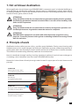
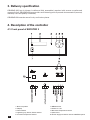
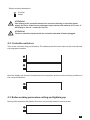
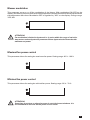
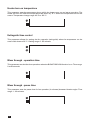
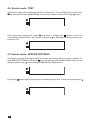
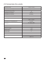
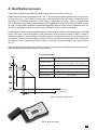
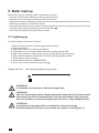
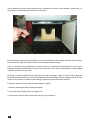
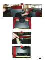
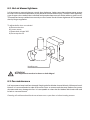
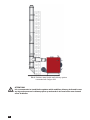
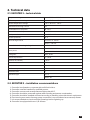
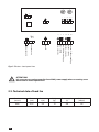
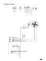
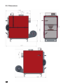
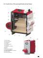
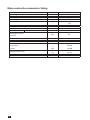
INSTRUCTION MANUAL
& SERVICE MANUAL
HOT AIR BLOWER
ORLIGNO 600
INSTRUCTION MANUAL
Content
1. Hot air blower destination . . . . . . . . . . . . . . . . . . . . . . . . . . . . . . . . . . . . . . . . . . . . . . . . . . . . . . . 3
2. Principle of work . . . . . . . . . . . . . . . . . . . . . . . . . . . . . . . . . . . . . . . . . . . . . . . . . . . . . . . . . . . . . . . . 3
3. Delivery specification . . . . . . . . . . . . . . . . . . . . . . . . . . . . . . . . . . . . . . . . . . . . . . . . . . . . . . . . . . . . 4
4. Description of the controller . . . . . . . . . . . . . . . . . . . . . . . . . . . . . . . . . . . . . . . . . . . . . . . . . . . . . . 4
4.1. Front panel of EKOSTER 3 . . . . . . . . . . . . . . . . . . . . . . . . . . . . . . . . . . . . . . . . . . . . . . 4
4.2. Controller switch-on . . . . . . . . . . . . . . . . . . . . . . . . . . . . . . . . . . . . . . . . . . . . . . . . . . . 4
4.3. Boiler working parameters setting and lightning up . . . . . . . . . . . . . . . . . . . . . . . . 4
4.4. Service mode - OPERATION PARAMETERS . . . . . . . . . . . . . . . . . . . . . . . . . . . . . . 6
4.5. Service mode - LANGUAGE . . . . . . . . . . . . . . . . . . . . . . . . . . . . . . . . . . . . . . . . . . . . 9
4.6. Service mode - TEST . . . . . . . . . . . . . . . . . . . . . . . . . . . . . . . . . . . . . . . . . . . . . . . . . 10
4.7. Service mode - SERVICE SETTINGS . . . . . . . . . . . . . . . . . . . . . . . . . . . . . . . . . . . . 10
4.8. Room temperature controller . . . . . . . . . . . . . . . . . . . . . . . . . . . . . . . . . . . . . . . . . . . 11
4.9. Temperature sensor damage . . . . . . . . . . . . . . . . . . . . . . . . . . . . . . . . . . . . . . . . . . . 11
5. Boiler start-up . . . . . . . . . . . . . . . . . . . . . . . . . . . . . . . . . . . . . . . . . . . . . . . . . . . . . . . . . . . . . . . . . . 13
5.1. Lightning up . . . . . . . . . . . . . . . . . . . . . . . . . . . . . . . . . . . . . . . . . . . . . . . . . . . . . . . . . . 14
5.2. Stoking hot air blower . . . . . . . . . . . . . . . . . . . . . . . . . . . . . . . . . . . . . . . . . . . . . . . . . 14
6. Maintenance . . . . . . . . . . . . . . . . . . . . . . . . . . . . . . . . . . . . . . . . . . . . . . . . . . . . . . . . . . . . . . . . . . . 15
6.1. Hot air blower maintenance . . . . . . . . . . . . . . . . . . . . . . . . . . . . . . . . . . . . . . . . . . . . 15
6.2. Hot air blowers tightness . . . . . . . . . . . . . . . . . . . . . . . . . . . . . . . . . . . . . . . . . . . . . . 17
6.3. Fan maintenance . . . . . . . . . . . . . . . . . . . . . . . . . . . . . . . . . . . . . . . . . . . . . . . . . . . . . 17
2
1. Hot air blower destination
Wood gasification hot air blower type ORLIGNO 600 is commonly used in industrial buildings or
other facilities as: warehouses,workshops, hangars,tents or outbuildings in places where there's
no heating installation. They're also used as a source of hot air in technological purposes in drying
houses of wood, grains, herbs or fruits.
TTENTION!
A
Using fuel different than the recommended not guarantees optimum boiler operation
and achieving parameters featured in technical data. It can also affect durability of the
boiler and its components.
TTENTION!
A
Using fuel different than the recommended is treated as wrong boiler operation and
resultant performance irregularities cannot be reason for complaint.
TTENTION!
A
ORLIGNO 600 is equipped in controller with wide temperature range fit for every
purposes. Controller protects boiler against overheating with blow fan turning off and
back fan activation.
2. Principle of work
Gasification boilers utilize process of dry, pyrolitic wood distillation. During wood burning with
limited amount of air, wood changes into charcoal. Gasification process creates large amount of
wood gases which are directed to ceramic nozzle and burned in flame form in bottom chamber.
This method of wood burning efficiently make use of wood as a fuel.
Heat is transfered through loading, burning chamber's walls and vertical heat exchanger to
circulating cold air between inner and outer ORLIGNO 600 bodies.
Heated air is then blown directly through outlet located in upper part of hot air blower to the
premise.
Stage four
Exhaust gases at temp. 160°C
are emitted through boiler flue
Stage one
Wood drying
and degassing temp. 450°C
Stage two
Burning of mixed wood gases with
secondary air at temp. 560°C
Stage three
Burning up the flame and heat
emission at temp. of 1200°C
3
3. Delivery specification
ORLIGNO 600 hot air blower is delivered fully assembled, attached with screws to pallet and
wrapped in foil. ORLIGNO 600 comes with: set of cleaning tools 3 pcs and documentation (manual,
warranty card and quality certificate).
ORLIGNO 600 must be stored in dry and indoor places.
4. Description of the controller
4.1. Front panel of EKOSTER 3
1. Device symbols
2. Display
3. Failure diode
4. Lightning-up / Pause / Return button
5. Increase temperature button
4
6. MENU button
7. Switch on / off
8. Decrease temperature button
9. 2,5 A fuses
10. Power supply socket for remote CONTROL panel
Display symbols description
front fan
heater
TTENTION!
A
If the display of the controller doesn't turn on after switching on check the power
supply and fuses. If the fuses are damaged replace them both with new 2,5 A ones. If
the display is still off – contact the service.
TTENTION!
A
The fuses should be replaced with the controller switched off and unplugged.
4.2. Controller switch-on
Turn on the controller using on/off switch. The display should show the name of the controller and
the programme number.
Next the display will show the temperature from the sensor and the current working condition of
the connected devices.
4.3. Boiler working parameters setting and lightning up
During boiler operation the display shows the current temperature from the sensor.
5
By pressing
or
, it is possible to adjust the temperature setting of the boiler. Temperature
range from 50 °C to 120 °C .
ATTENTION!
Symbol or symbol on the display inform about the current temperature change
in the boiler means that the temperature is changing toward desired, means that
the temperature is decreasing towards the “HI” parameter.
4.4. Service mode - OPERATION PARAMETERS
Service mode is for setting changes and various parameters of the devices, e.g. fan and
heater operation. Press
for a few seconds to enter service mode. The display will show
WORK PARAM. Further pressing
results in entering settings for various operation
and
buttons to change the selected parameters.
parameters. Use
Fan hysteresis
This parameter shows how much the temperature must fall from set temperature to turn the fan
on. Temperature setting range: 0 °C to 9 °C.
6
Blower modulation
This parameter turns on or off the modulation of the blower. With modulation ON (YES on the
display) the blower will slow down when the temperature reaches the set level and will speed when
the temperature falls down. Modulation OFF is signalled by “NO” on the display. Change range:
YES / NO.
TTENTION!
A
Fan modulation is limited to hysteresis i.e. it works within the range of set boiler
temperature and set hysteresis parameter. Below hysteresis the fan works with
maximum set power.
Maximal fan power control
This parameter allows for setting the maximum fan power. Setting range: 30 % - 100 %
Minimal fan power control
This parameter allows for setting the minimal fan power. Setting range: 30 % - 70 %
TTENTION!
A
Some fans do not turn on when the power is set at the lowest minimum. It is
recommended to increase the fan power in such cases.
7
Heater turn-on temperature
This parameter sets the temperature above which the heater turns on and starts operating. The
heater will turn off when the temperature falls down by 10 °C below the temperature set on the
sensor. Temperature change range: 40 °C to 120 °C.
Extinguish time control
This parameter allows for setting the fan operation (extinguish) when the temperature on the
sensor falls down to 30 °C . Setting range: 0 - 45 minutes.
Blow through - operation time
This parameter sets the fan time operations when the BLOW THROUGH function is on. Time range:
0 to 90 seconds.
Blow through - pause time
This parameter sets the pause time for fan operation (in minutes) between blowthroughs. Time
range: 1 - 60 minutes.
8
TTENTION!
A
Blow through function is activated when the boiler reaches the set temperature.
TTENTION!
A
Blow through will not activate when:
1. The temperature on the sensor will be 10 °C higher than the temperature set for the boiler.
2. The temperature will be lower than set by the “HI” parameter.
TTENTION!
A
Setting the operation time for 0 will turn off the blow through function
Fan pause - stoking
Parameter setting the fan pause time necessary for stoking the boiler. Time range: 0:30 to 9:30
minutes.
4.5. Service mode - LANGUAGE
Service mode is for setting the language of the control panel. To enter the LANGUAGE service
mode press
for a few second until WORK PARAM. shows on the display. Choose the language
(Polish/English/German) using
button.
9
4.6. Service mode - TEST
This function helps with checking the accuracy of connection. To enter TEST service mode press
for a few seconds until WORK PARAM.; shows on the display. Choose TEST using
button.
Each consecutive pressing the button
will result in showing the
symbol by the icon
or , buttons individual devices are
representing individual device: fan / heater. By pressing
turned on / off.
4.7. Service mode - SERVICE SETTINGS
This function cancels all settings entered by the user and returns devices to service settings. To
enter SERVICE SETTINGS mode press
for a few seconds until WORK PARAM. shows on the
display and then using
button change to SERVICE SETTINGS screen.
By pressing
10
button again changes to service settings save screen. To save the changes press
.
4.8. Room temperature controller
It is possible to install room temperature controller which will turn on/off the heater depending on
the temperature in the room. The heater will turn on when the temperature on the sensor reaches
the minimal set level.
To install the room temperature controller:
1. Remove circuit armature from the socket marked
, on the back of the controller.
2. Install the room temperature controller in the socket.
4.9. Temperature sensor damage
If the temperature sensor is damaged the controller will STOP and - will appear on the display
instead of the temperature. The red diode FAILURE will be on .
11
4.10. Technical data of the controller
Temperature range
- 58 °C to + 390 °C
Boiler temperature settings
+ 50 °C to + 120 °C
Heater temperature settings
+ 40 °C to + 120 °C
Smooth blow-through control
Controllable min. fan power
yes
30 - 70 %
Controllable max. fan power
30 - 100 %
Fan hysteresis
0 °C to 9 °C
Heater hysteresis
Blow-through control
10 °C
work time: 0 - 90 sec.
pause: 1 - 60 min.
Controllable boiler extinguishing time
Input power
Voltage AC
0 - 45 min.
fan: 100 VA / 230 V
heater: 100 VA / 230 V
230 V, 50 Hz
Electrical protection
2 x 1,25 A
Relative air humidity
< 95 %
Protection class
Insulation class
Ambient temperature
IP 40
II
0 °C to + 40 °C
Software class
A
Operation type
fan: 1Y
heater: 1B
12
4. Gasification process
Gasification hot air blower ORLIGNO 600 must operate in specified conditions.
Optimal hot air blower temperature is 85 - 90 °C. At lower temperatures gasification process is not
running correctly – hot air blower cannot reach nominal power and fuel usage is relatively higher.
Wood drying in loading chamber is crucial stage in gasification process – at lower temperatures
hot air blower cannot reach right temperature and gasification process is disturbed. Main source
of heat in Orligno 600 is gas flame created during gasification process, if main conditions won’t be
met for proper gasification process, amount and quality of flame will be inadequate.
Essential factor influencing right gasification process is quality, moisture content and type of burned
wood. The best is hardwood (beech, oak, harnbeam) with moisture content 15-20%. Lenght of
wood should be the same as depth of loading chamber. Usage other types of wood like spruce is
acceptable, however heat exchanger pollution will increase and time between boiler stoking will
decrease. In order to determine proper moisture content it is recommended to use moisture meter
(pic. 3)
Appropriate wood assures correct boiler operation. Usage of wood with different parameters other
than recommended will affect proper work of boiler.
Fuel specification
Main fuel
wood logs, wood in halves and quarters
small pieces of wood, shavings, briquettes
must be burned together with wood logs
alternative fuel
Optimum humidity
lenght
Outside drying
- in months
50 cm
diameter
15 - 25 cm
moisture content
15 - 25 %
calorific value
4,1 - 4,4 kW
Wood humidity [%]
Tree’s chopping off
Pic.2 Wood humidity chart
Pic.3 Moisture meter
13
5. Boiler start-up
Before first start-up of Orligno 600 it is advisable to check:
- if there’s no flammable substances close to hot air blower
- tightness of connecting pipe between flue and chimney
- placement of bottom chamber’s firebricks as they must be placed directly under the nozzle hole
- if 230 V power plug is connected to socket
- if front fan is blowing the air to upper chamber through primary air channels located on front left
and right side of upper chamber (fan is activated with
).
- if front fan is blowing air through holes in nozzle
5.1. Lightning up
In order to light up in the hot air blower:
1. Pull in chimney flap lever (exhaust gases duct opened).
2. Open upper door.
3. Put papers, small wood pieces and light up.
4. Close upper door and open bottom one thus creating natural draft.
5. Wait 15-20 minutes to create ember layer covering whole upper chamber.
6. Fully load the chamber with halves of wood logs put along the chamber.
7. Close upper and bottom door.
8. Close chimney flap lever (IMPORTANT!).
9. Turn on fan on the controller by pressing
.
Display will show
informing about lightning up process.
TTENTION!
A
It is forbidden to turn the fan on with opened upper door.
TTENTION!
A
Take into consideration loading chamber depth while stoking the hot air blower. Wood
dimensions larger than recommended may cause troubles during closing the upper
door. It is necessary to avoid closing upper door with force – it may damage the door.
TTENTION!
A
Acceptable wood humidity of 25% is reached after 12 months of drying.
Recommended level of 15-20% is reached after 24 months of seasoning (Pic. 2)
14
5.2. Stoking hot air blower
Burning period in ORLIGNO 600 hot air blower is 7-12 hours. In order to avoid discomfort with fuel
stoking it is recommended to check fuel level each 5-7 hours. To check fuel level and possibly stoke
the blower one should:- Turn the fan off before stoking the boiler by pressing
which is signalled
on the display by along with the countdown to restart. Stoking time is set in the service mode
OPERATION PARAMETERS – see Fan Pause - stoking.
- Open chimney flap lever
- Open upper door and stoke upper chamber.
- Close the door, chimney flap and turn on the fan on the controller
Keep in mind that during the fuel stoking some wood parts may get between flue flange and
chimney flap which would make impossible to close the flap tightly.
During fuel stoking (it is recommended to stoke the fuel after wood fully burned till glow layer) stir
with poker ash deposited on the sides of loading chamber.
6. Maintenance
6.1. Hot air blower maintenance
Boiler needs to be serviced for idle time (summer season, absence of user).
Sides of loading, ash chamber, chimney flap and heat exchanger needs to be cleaned regularly (it
is advisable to burn softwood like spruce to remove pitch before summer season). After burning
softwood leave the boiler open – in this way damp is not condensing on the sides of boiler.
TTENTION!
A
It is advisable to control the hot air blower annually in order to prepare it well for the
next heating season.
15
Ash created during wood burning falls down through the nozzle to ash chamber, that’s why it is
advisable to remove the ash from bottom chamber.
Each time before lightning up the boiler it is recommended to clean loading chamber. Ash needs to
be removed through the nozzle. Use the tools supplied with the boiler.
Pitch is created during gasification process. Amount of created pitch depends on wood type,
humidity and water temperature coming out and into the boiler. It is recommended to clean loading
chamber at least once a month.
Particles in exhaust gases flowing through the heat exchanger create on their surface deposit.
Deposition causes lowering of inner pipes dimension and lowering of heat exchange surface. That
is why it is necessary to clean heat exchanger pipes each time after boiler stoking.
Follow the steps of how to clean heat exchanger’s pipes:
1. Remove back upper heat exchangers panel.
2. Unscrew bolts holding heat exchangers' lid.
3. Clean each of pipes with round tools moving it up and down.
16
1
2
3
17
6.2. Hot air blower tightness
It is important to assure tightness, mostly door tightness. Leaks cause that exhaust gases escape
to boiler room but most importantly it may leads to uncontrolled burning. To assure door tightness,
rope of upper door needs to be controlled and qresed at least once a 2 weeks with any gresce or oil.
This assures that rope adhesives correctly to door frame. Hot air blower tightness can be assured
also by hinges regulation.
To adjust boiler door one should
a) Remove the door
b) Loosen screw
c) Rotate both hinges 360°
d) Screw up the nut.
blocking nut
TTENTION!
A
Door adjustment needs to be done on both hinges!
6.3. Fan maintenance
It is important to keep both fans cleaned. Keeping the fan blades cleaned directly influences hot air
blower. It is recommended to take off front fan cover to remove ash that may leads to fan power
decrease and may damage the fan. It is acceptable to clean the fan blades with brush with soft
bristle or vacuum cleaner.
Cleaning of both fans should be done at least once a year after or before heating season.
SERVICE MANUAL
Contents
1. Installation . . . . . . . . . . . . . . . . . . . . . . . . . . . . . . . . . . . . . . . . . . . . . . . . . . . . . . . . . . . . . . . . . . . . . 19
1.1. Hot air blower-room ventilation . . . . . . . . . . . . . . . . . . . . . . . . . . . . . . . . . . . . . . . . . 20
1.2. Supply air ventilation . . . . . . . . . . . . . . . . . . . . . . . . . . . . . . . . . . . . . . . . . . . . . . . . . 20
1.3. Exhaust ventilation . . . . . . . . . . . . . . . . . . . . . . . . . . . . . . . . . . . . . . . . . . . . . . . . . . . 20
1.4. Hot air blower connection to chimney system . . . . . . . . . . . . . . . . . . . . . . . . . . . 20
2. Technical data . . . . . . . . . . . . . . . . . . . . . . . . . . . . . . . . . . . . . . . . . . . . . . . . . . . . . . . . . . . . . . . . . . 22
2.1. EKOSTER 3 – technical data . . . . . . . . . . . . . . . . . . . . . . . . . . . . . . . . . . . . . . . . . . . . 22
2.2. EKOSTER 3 – installation recommendations . . . . . . . . . . . . . . . . . . . . . . . . . . . . . 22
2.3. Technical data of heater . . . . . . . . . . . . . . . . . . . . . . . . . . . . . . . . . . . . . . . . . . . . . . . 23
2.4. Electric scheme . . . . . . . . . . . . . . . . . . . . . . . . . . . . . . . . . . . . . . . . . . . . . . . . . . . . . . 24
2.5. Dimensions . . . . . . . . . . . . . . . . . . . . . . . . . . . . . . . . . . . . . . . . . . . . . . . . . . . . . . . . . . 25
2.6. Construction of the wood gasification hot air blower . . . . . . . . . . . . . . . . . . . . . . 26
3. Troubleshooting . . . . . . . . . . . . . . . . . . . . . . . . . . . . . . . . . . . . . . . . . . . . . . . . . . . . . . . . . . . . . . . . 28
4. Ending . . . . . . . . . . . . . . . . . . . . . . . . . . . . . . . . . . . . . . . . . . . . . . . . . . . . . . . . . . . . . . . . . . . . . . . 28
1. Installation
Hot air blowers should be installed according to binding rules and norms.
Rules and norms should be followed according to solid fuel boiler assembly in countries in which
the hot air blower is sold.
1. Boiler room height should be at least >2,2 m for easier boiler cleaning.
2. Distance from boiler room walls should allow for free access to boiler sides and should be at
least as shown on picture „ORLIGNO 600 placement”.
3. Boiler room should be free of any electric installation not intended for boiler installation.
Pic.1 ORLIGNO 600 placement
20
1.1. Boiler-room ventilation
According to european safety regulations each boiler room should have supply-exhaust ventilation
ensuring correct hot air blower operation and user’s safety. Lack of ventilation or its obstruction
is the main reason of incorrect hot air blower operation (i.e. hot air blower cannot reach set
temperature). Exhaust ventilation removes from boiler room used air and harmful gases. Boiler
room with natural draught cannot have installed mechanical ventilation.
1.2. Supply air ventilation
1. Ventilating duct section should have at least 50% area of chimney’s section and not less than
20 x 20 cm. Duct should be placed 1 m above the floor.
2. Ventilating duct should have installed device for air flow control; device shouldn’t limit duct
section above 1/5. Ventilating duct should be made of non-inflammable material.
1.3. Exhaust ventilation
1. Exhaust duct should be made of bricks with section of at least 25% of chimney section not
less 14 x 14 cm. Inlet hole cannot have any devices that reduce its section. Outlet hole should
be placed close to the ceiling led out 1,5 m above the roof. Ventilating duct should be made of
non-inflammable material.
2. Height of the boiler room min. 2,2 m.
1.4. Hot air blower connection to chimney system
Chimney system for hot air blower should be installed according to norm EN -13384 and below
recommendations should be taken into account:
- p
ipe connecting hot air blower with chimney should be as short as possible (with minimal
distances to walls acc. to pic. 1) with ascend of at least 5º
- p
ipe diameter connecting hot air blower with chimney must be at least the same as hot air blower
flue
- chimney draft cannot be smaller than the one required in technical data of this manual
- pipe connecting hot air blower with chimney should be made of temperature resistant material
21
Pic.2 Stainless steel double wall chimney system
connected with Orligno 600
ATTeNTION!
It is recommended to install draft regulator which stabilizes chimney draft and in case
too big underpressure in chimney opens up and sucks in air from boiler room instead
of hot air blower.
22
2. Technical data
2.1. EKOSTER 3 – technical data
Temperature range
from - 58 °C to + 390 °C
Boiler temperature settings
from + 50 °C to + 120 °C
Heater temperature settings
from + 40 °C to + 120 °C
Smooth blow-through control
yes
Controllable min. fan power
30 - 70 %
Controllable max. fan power
30 - 100 %
Fan hysteresis
from 0 °C to 9 °C
Heater hysteresis
10 °C
Blow-through control
work time: 0 - 90 sec.
pause: 1 - 60 min.
Controllable boiler extinguishing time
Input power
0 - 45 minute
fan: 100 VA / 230 V
heater: 100 VA / 230 V
Voltage AC
230 V, 50 Hz
Electrical protection
2 x 1,25 A
Relative air humidity
< 95 %
Protection class
IP 40
Insulation class
II
Ambient temperature
0 °C to + 40 °C
Software class
A
Operation type
fan: 1Y
heater: 1B
2.2. EKOSTER 3 – installation recommendations
1.Controller is adjusted to cooperate with solid fuel boilers.
2.Controller must be installed by qualified person.
3.Controller cannot work at temperatures higher than 40°C.
4.Controller should be protected against water flooding and steam condensation.
5.Controller should be installed and used according to handling rules with electric equipment.
6.Fuse burning as a result of wrong pump connection is not considered as a warranty matter.
7.It is recommended to check controller’s settings before lightning up.
8.Controller is equipped with two 1,25 A fuses.
23
7
8
N
230 power supply - neutral
N
N
heater - neutral
N
N
front fan - neutral
N
L
230 power supply - live
L
L
heater - live
L
L
front fan - live
L
T1
ground
hot air sensor
room thermostat
T1
Rys.3 Ekoster – back panel view.
TTENTION!
A
It is necessary to unplug controller from 230V power supply when connecting room
thermostat or fuses replacement.
2.3. Technical data of back fan
24
Rotation
[rot/min]
Power
[kW]
Current
I zn[A]
Weight
[kg]
Power supply
[V]
Noisiness
[dB(A)]*
2800
0,55
4,0
14
230
86
230V~
T1
KA
KM
L
N
N
N
front fan - neutral
heater - neutral
230 power supply - neutral
KA
KM
L
230 power supply - live
front fan
heater
contactor's coil
working contacts of contactor
L
heater - live
T1
front fan - live
ground
hot air sensor
room thermostat
2.4. Electric scheme
25
N
N
N
L
L
L
2.5. Dimensions
26
2.6. Construction of the wood gasification hot air blower
1. Hot air outlet
2. Hot air controller
3. Loading door
4. Front fan
5. Combustion door
6. Firebricks
7. Combustion chamber
8. Nozzle
9. Heater
10. Tube heat exchanger
11. Ceramic moulders
12. Loading (gasification) chamber
13. Chimney flue
14. Chimney flap lever
27
Main construction parameters’ listing
Power
Power range
Efficiency
Boiler class (EN 303-5)
Boiler weight
Volume of loading chamber
Loading hole width/lenght
Burning period
Wood logs lenght
Humidity
- recommended
Fuel usage for power:
- nominal
Temperatures setting range
Protection level of controller
Voltage/Frequency
Exhaust gases parameters (at nominal power):
- temperature
- stream
Required chimney draft
Flow of hot air
Power intake
28
kW
kW
%
kg
dm3
l
mm
h
cm
%
25
7,5 - 25
~ 91
3
546
120
120
260/432
7-12
50
15-25
kg/h
8,2
°C
V/Hz
50-120
IP 40
230/50
°C
kg/s
mbar
Pa
m3
W
170-200
~0,0088
min 0,15
min 15
~1500
620
3. Troubleshooting
Symptom
Hot air blower
cannot reach set
temperature
Smoking from heat
exchanger lid
Smoking from
loading door
Smoking from door
Controller doesn’t
work
Fan doesn’t work
Loud work of fan
Reason
Action
Wrong lightning up
Check. 5.1 „Lightning up”
Too humid wood
Humidity control – use wood with proper
parameters
Clogged primary air channels
Call service – after warranty service
Clogged secondary air pipes
Call service – after warranty service
Polluted heat exchanger’s pipes
Clean with round tool or call service - after
warranty service
Unproper mix of air with wood
gases
Call service – after warranty service
Damaged nozzle
Replace – after warranty service
Smoking from fan gasket
Replace – after warranty service
Damaged fan
Replace – after warranty service
damaged rope
Screw in lid tightly, replace rope or call service
hardened rope
Replace rope - after warranty service
Damaged heat exchanger's lid
Replace lid - call service
Strong wind force exhaust gases
into the chimney
Consider installation of appliances supporting
chimney draft (WKO)
Unproper chimney parameters
Rebuild chimney, chimneys weeper assistance
Leakiness from door
Door adjustment according to 5.2.
Used rope - leak
Rope replacement or call service - after warranty
service
Damaged door
Door replacement
No voltage in the grid
Check electric installation
Damaged fuse
Fuse replacement
Damaged wire
Wire control or replacement
Damaged boiler sensor
Call service
Damaged controller
Call service
Damaged fan
Fan replacement – call service
Fan blades blocked
Check and clean fan
Damaged bearings
Call service- fan replacement
Damaged condenser
Call service – condenser replacement
Loosen fixing of fan
Fixing control, screw in
Polluted fan blades
Control, cleaning
Pitch in fan casing
Control, cleaning
29
Symptom
Weak work of fan
Explosions in hot
air blower
Reason
Polluted fan blades
Action
Control,cleaning
Fan flap clogged with pitch
Clean or call service
Wrong lightning up
Check “Lightning up“
Too small chimney draft (below 10Pa)
Rebuild chimney. Install exhaust fan WKO
Too big chimney draft (above 20 Pa)
Install draft stabilizer
Too dry wood (humidity below 15 %)
Mix with wood with higher humidity content
Polluted heat exchanger’s pipes
Clean pipes or call service
4. Ending
Present appliance is marked according to European Directive 2002/96/EC on waste electrical and
electronic equipment.
Symbol placed on the components or attached documents means that appliance is not classified
as a household waste.
Scrapping should take place in special collection point in order to reuse electrical and electronic
components.
30
31
EKO-VIMAR ORLAŃSKI Sp. z o.o.
48-385 Otmuchów, ul. Nyska 17b
POLSKA / woj. opolskie
T +48 77 400 55 80-81, 400 55 91
f +48 77 439 05 03, 400 55 96
e [email protected]
www.orlanski.pl
IO_ORLIGNO_600_22052013_EN