1
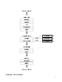
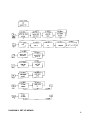
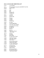
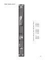
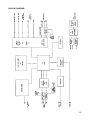
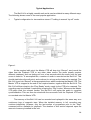
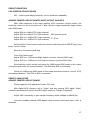
Operator’s &
Service manual
Model 6110
Digital audio lay-off
recorder
Version 1.0
BEL (Digital Audio) Ltd.
Invicta Works Elliott Road Bromley Kent BR2 9NT UK
Tel: +44 (0)20 8460 7299 Fax: +44 (0)20 8460 0499
Email: [email protected]
Web: www.bel-digital.com
BEL 6110 Lay-off Recorder
V1.0
The Version 1.0 BEL 6110 is a CE marked programmable version of the popular
BDE-6000S. It provides for more comprehensive control via an RS422 serial link and allows
various operating parameters to be adjusted. These settings are retained on power down.
This version has further enhancements to the AES digital audio synchronisation facilities
enabling the digital output to be referenced to AES, video or word clock sources.
Contents
DESCRIPTION
5
OPERATION AND FRONT PANEL CONTROLS
5
Input Sensitivity
5
Record Switch
5
Record switch in Serial Mode
6
Play Switch
6
Play Switch in Serial Mode
6
^, Set and Page Keys
6
Serial Control
9
a) JOG, SHUTTLE and DMC
9
b) Cue-up with DATA and Pre-roll
9
c) Transport commands
9
Striping
LCD Display
DIGITAL AUDIO INPUT-OUTPUT
Digital Referencing
9
10
11
11
POWER-UP
11
CONNECTIONS
12
EMC COMPLIANCE
12
REMOTE CONTROL CONNECTOR
13
MEMORY ADDITION
14
POWER ON RESET
14
SPECIFICATION
15
6110 RS422 IMPLEMENTATION LIST
16
DETAIL OF SWITCHES ON FRONT - FIGURE 2
17
DETAIL OF DEFAULT LCD - FIGURE 3
17
REAR PANEL VIEW - FIGURE 4
17
FRONT PANEL LAYOUT
18
3
REAR PANEL LAYOUT
19
BLOCK DIAGRAM
20
TROUBLESHOOTING
21
APPLICATION NOTES
22
Introduction
23
Typical Applications
24
SERVICING INFORMATION CONTENTS
26
4
BEL 6110
Digital Audio Lay-off Recorder
DESCRIPTION
The BEL 6110 is a device that will store audio and time code information in a digital
form. This information can then be replayed synchronised to an incoming time code. The
basic unit contains an 8 Mbyte circular memory which can record up to 42 seconds of
stereo audio. This memory can be increased, to a maximum of 32 Mbyte, providing
recording times of 84 secs and 168 secs respectively. The description below refers to the
8 Mbyte version but it also applies to all versions that differ only in recording times.
The BEL 6110 will initially fill its memory in a linear way and provide a warning on an
LED when the recording is within 5 Seconds of the end of this memory. If recording is
allowed to exceed the memory capacity the unit will enter a circular mode where only the
most recent 42 Seconds of audio is retained. In the follow mode, recording is only allowed
in the presence of a valid time code. When the same time code is subsequently applied to
the unit the audio is replayed in synchronism. The operation of the unit can be controlled
by two push switches. The status of the BEL 6110 is displayed on LED indicators and a
liquid crystal display (LCD). These controls and indicators are duplicated on a remote
control unit. Serial control (RS422) is programmable from the set-up menu.
OPERATION AND FRONT PANEL CONTROLS
There are six front panel controls. From left to right, these are:INPUT SENSITIVITY
This control permits the amplitude of the signal entering the unit to be adjusted. For
unity gain, set this control to the centre position. For other settings, with audio and running
time-code present, press the Record switch and adjust the control to provide the desired
level. The Peak Program indicators to the left of this control give a visual indication of
optimum settings. For normal operation, the yellow LED indicators should be on constantly,
with the green LED indicators flashing on peaks.
RECORD SWITCH
Providing there is time-code present, pressing ÒRecordÓ starts recording new audio
with its corresponding time-code. A second press of ÒRecordÓ returns the unit to Follow
mode as does pressing ÒPlayÓ, or interrupting the time-code for example, by stopping or
searching the edit VT. The red LED above the Record switch indicates ÒRecordÓ mode:this
indicator will flash 5 seconds before the memory is full. The amber LED indicators to the
left and right of the record switch indicate the position of the stored audio relative to the
incoming time-code. When the in-coming time-code is ÒbeforeÓ the stored audio, the left
LED will light, when it is locked both LEDs will light and when it is ÒafterÓ only the right LED
will be lit.
5
RECORD SWITCH IN SERIAL MODE
Depressing the Record switch while in serial mode will start the BEL 6110 recording
at the displayed time code. A second press will stop the recording. This enables the BEL
6110 to record while attached to a play-only editor port. This facility enables editing
equipment with limited numbers of record ports to be used more effectively.
PLAY SWITCH
Pressing ÒPlayÓ retrieves the stored audio from the start of the most recent recording.
Whilst in ÒPlayÓ mode, incoming time-code is ignored. A second press of ÒPlayÓ returns the
unit to the Follow mode.
PLAY SWITCH IN SERIAL MODE
Pressing ÒPlayÓ whilst in serial mode retrieves the stored audio information starting
at the displayed time. Pressing a second time will stop this process.
^, SET AND PAGE KEYS
Refer to the diagrams 1 and 2 for the details of operation.
Basically:The ÒSetÓ key selects the different modes to be changed
The ^ key is used to make a change
The ÒPageÓ key is used to access programmable features within a Set mode.
6
DIAGRAM 1. SET-UP MENUS
7
DIAGRAM 2. SET-UP MENUS
8
SERIAL CONTROL
The BEL 6110 can be controlled by the editing equipment, be sending commands
down a serial communication line. The serial communication protocol must conform to the
RS422 standard as implemented by SONY©. The BEL 6110 memory will appear to the
user exactly like a section of tape which has been pre-striped. The stripe can be set to start
on the hour from 0 to 23 hrs, and the length of recording which can be accommodated will
depend on the size of the installed memory (42, 84, or 168 seconds for stereo). The
ÒWindowÓ provided by the BEL 6110 memory can be recorded and replayed in the same
way as magnetic tape. If recording is attempted outside this window, then no recording will
take place, and no record flags will be returned by the equipment.
The serial mode is selected from the Set-Up menu. The SONY© protocols shown in
Section 7 are accepted by the BEL 6110. The unit will identify itself as a BVW 75 recorder.
This particular tape recorder system was selected because it responds to a set of
commands similar to those supported by the BEL 6110. However, the BEL 6110 does not
exactly mimic this tape recorder. In particular, the BEL 6110 is a purely electronic device,
as such it is not subject to the inertial effects invariably present in any mechanical tape
recorder. To the user, the response of the BEL 6110 appears to be instant. The main
differences in operation can be summarised as follows:a) Jog, Shuttle and DMC
Each time a request to move one frame in either direction is detected, the BEL 6110
will respond by playing a 0.1 second burst of audio in the forward directional normal speed.
This facility eases the precise location of any required sound.
b) Cue-up with DATA and PRE-ROLL
These macro commands operate considerably faster on the BEL 6110 than is
possible on any tape based system. The cue point (or pre-roll point) is found in a maximum
of 60 microseconds from receipt of the relevant command.
c) Transport commands
Commands such as Stop, Rewind, Fast Forward, etc., become effective immediately
they are received. No delay will be apparent, since there is no mechanical inertia in the
system.
STRIPING
The memory in the BEL 6110 is striped when any roll mode is selected. (The stripe
setting is in one hour increments from 0 to 23 Hrs.) Any audio information stored in the
memory at this time is preserved, but the associated time code is over-written.
9
LCD DISPLAY
This is a Supatwist LCD display with LED backlighting. It is a multi-function display,
showing the set-up modes and the current status of the unit:Record
Stop
Play
Locked
=
Ü
Ý
5
Unit in record mode, recording audio and time-code (follow-mode)
No readable code
Unlocked replay of audio
}
Unit locked to time-code in replay
Reading time-code before stored audio
Reading time-code after stored audio
5 seconds before the audio store is full
10
DIGITAL AUDIO INPUT-OUTPUT
The digital interface is AES/EBU compatible at a sampling rate of 48kHz. A sample
rate converter is used on the input allowing the conversion of 32kHz, 44.1kHz digital
sources to 48kHz. The digital REF AES input can be used with sampling rates other than
48kHz but the unit is optimised for 48kHz.
The digital output is always operating concurrently with the analog output. The
source, however, is either analog or digital.
DIGITAL REFERENCING:1)
2)
3)
4)
5)
Audio in - The BEL 6110 locks to incoming AES signal connected to the AES
digital input.
AES - The BEL 6110 locks to the external AES signal connected to the AES
REF digital input. (48kHz)
Word - The BEL 6110 locks to the external word signal connected to the word
input. (48kHz) (TTL levels)
Video - The BEL 6110 locks to the external video signal PAL or NTSC (auto
select) connected to the video input. (1V Pk/Pk)
Internal - The BEL 6110 locks to the internal crystal oscillation. (48kHz
±25ppm)
POWER-UP
On power-up, the LCD will show the Model Number, The Version Number and the
maximum audio memory fitted (either 8, 16 or 32 Mbyte). This display remains for a few
seconds, before resetting to the STOP mode. (A slight flickering of the display is normal
during this time, as the memory is being purged of random data.) The time taken to reset
is dependent on the memory fitted (i.e. longer for the 32 Mbyte version.)
11
CONNECTIONS
The rear panel has twelve connectors, a voltage selector and a combined IEC power
inlet switch and fuseholder. From left to right these are:Switch, Fuse, IEC 3 pin power inlet (combined EMI filter unit)
Mains power voltage selector (115V / 230V)
RS422 Serial Port 9-pin female miniature D-type (lockable)
Remote Control 9-pin female miniature D-type (lockable)
Time-Code Input 3-pin XLR type connector (female) for SMPTE input Balanced
Digital Ref: Word 50½ BNC (4k7½)
Digital Ref: Video 75½ BNC medium impedance (75½ termination link internal)
Digital Output (AES/EBU) male XLR 3-pin (110½)
Digital Input (AES/EBU) female XLR 3-pin (110½)
Digital Ref: AES (48kHz) female XLR 3-pin (110½)
Left and Right Audio Outputs 3-pin XLR type connector (male). Balanced Pin 2 hot.
Left and Right Audio Inputs 3-pin XLR type connectors (female). Balanced Pin 2 hot.
EMC COMPLIANCE
The BEL 6110 was designed and tested to comply with the EMC directive numbers
EN55103, EN55022, EN55082-1 and EN60950 when used as directed.
This unit must be used with an earthed mains lead to comply with the CE low voltage
directive.
CE
12
REMOTE CONTROL CONNECTOR
The pin assignment on the 9-pin miniature D-type connector is as follows:Pin
1
2
3
4
5
6
7
8
9
Function
Record Switch
Play Switch
Record LED
Ahead LED
Behind LED
+5V
Ground
Ground
Chassis
13
MEMORY ADDITION
To add memory to your BEL 6110 you will need to purchase extra memory modules
and an Eprom set.
To upgrade to 16m (84 secs stereo) you will require:1 off BEL 6110 memory module (8 Mbyte)
1 off BEL 6110 Eprom 16m - H
1 off BEL 6110 Eprom 16m - L
On CPU printed circuit board:Add memory module to Bank 1 and replace U22 with -H Eprom and U23 with -L
Eprom.
To upgrade to 32m (168 secs stereo) you will require:2 off or 3 off BEL 6110 memory modules (8 Mbyte) depending on existing memory
1 off BEL 6110 Eprom 32M - H
1 off BEL 6110 Eprom 32M - L
On CPU printed circuit board:Add memory modules to fill ALL banks (0-3) and replace U22 with -H Eprom and
U23 with -L Eprom.
To access CPU printed circuit board - remove power IEC connection and then
remove cover (19 off pozi type screws).
* see Printed Circuit Board layout drawing in service section.
POWER ON RESET
To reset the BEL 6110 to default settings proceed as follows:-
Power unit off
Power unit on and while the LCD display is showing the ÒLOGONÓ message Model/Version
etc, press the ÒSETÓ key and hold for approximately 3 seconds. A reset will now be initiated.
The display will acknowledge this by flashing the message Òpower-on resetÓ in the top left
corner of the LCD.
Default settings are:-
Digital Ref: Audio in
Tracking mode - follow, 1 frame flywheel
Audio Mode - stereo
Audio Source - Analog
LTC editor stripping start 00:00:00:00
LTC editor video system - PAL
14
SPECIFICATION
TV system
Frequency response
Dynamic range
Signal to noise ratio
Distortion
Conversion accuracy
Sampling rate
Inputs
Outputs
Digital I/O
Reference
RS422 serial port
Supply Voltages
Supply Currents
Fuse Ratings (semi delay)
PAL or NTSC
20Hz - 20kHz ± 1dB
96dB
-94dB. r.m.s. 20 - 20kHz
less than 0.015% at 1kHz
A/D 18 bit Delta Sigma
64 x oversampled
D/A 20 bit 8 x oversampled
48 kHz. (Internal reference)
Electronically balanced 25kW
Electronically balanced 50W
Max. drive capability +22dBu
(factory set for +18dBu)
Input AES/EBU 32 - 48kHz (nominally 48kHz)
Output AES/EBU 48kHz
1. Internal crystal (48kHz)
2. Audio Input - Locks to AES Input frequency
3. External AES/EBU (48kHz)
4. External Word Clock (48kHz) (TTL)
5. External video PAL/NTSC auto select (1Vpk-pk)
38.4 kbaud, 8 data bits 1 stop bit no parity
SONY© protocol
110-120VAC and 220-240VAC 50/60Hz
300MA @ 115VAC, 150MA @ 230VAC
500MA @ 115VAC, 250MA @ 230VAC
15
BEL 6110 RS3422 IMPLEMENTATION LIST
00.0C
00.11
00.1D
20.00
20.01
20.02
20.04
20.05
2X.11
2X.12
2X.13
20.20
2X.21
2X.22
2X.23
20.30
24.31
20.54
20.55
20.60
20.61
20.64
20.65
44.04
44.05
40.10
40.11
41.30
44.31
44.32
41.33
41.34
41.35
41.36
61.0A
61.0C
60.10
60.11
61.20
60.30
60.31
60.36
Local Disable
Device Request responds with BVW-75 (21.25)
Local Enable
Stop
Play
Rec
Standby Off
Standby On
Jog Fwd
Var Fwd
Shuttle Fwd
Rewind
Jog Rev
Var Rev
Shuttle Rev
Pre-Roll
Cue-Up With Data
Anti-Clog Timer Disable
Anti-Clog Timer Enable
Full EE Off
Full EE Off
Edit Off
Edit On
Time Code Preset
U-Bit Preset
In Entry
Out Entry
Edit Preset
Pre-Roll Time Preset
Tape/Audio Select
Servo Ref. Select
Head Select
Colour Frame Select
Timer Mode Select
TC Gen. Data Sense
Current Time Sense
In Data Sense
Out Data Sense
Status Sense
Edit Preset Sense
Pre-Roll Time Sense
Timer Mode Sense
16
DETAIL OF SWITCHES ON FRONT
Figure 2
DEFAULT LCD
Figure 3
REAR PANEL VIEW
Figure 4
17
Standard
Option 1
Option 2
42.24 Secs
84.48 Secs
168.96 Secs
8 Mbyte
16 Mbyte
32 Mbyte
Audio Store Memory Options - Maximum in Stereo
FRONT PANEL LAYOUT
18
REAR PANEL LAYOUT
19
BLOCK DIAGRAM
20
TROUBLESHOOTING
The Bel 6110 is designed and constructed to ensure a long and fault free life, but if
a problem does occur the following guidelines are provided.
The unit is constructed using 2 main printed circuit boards and 7 sub assembly
boards.
The 2 main PCBÕs carry the processor/DSP circuits (CPU) and the analog/digital
input output systems (ADAREF). Seven smaller PCBÕs carry:1.
The keyboard interface
2.
The LCD interface
3.
A system power supply
4.
ÔAnalogÕ I/O - Protection and EMC suppression
5.
Digital AES/EBU I/O protection and EMC suppression
6.
Time-code, remote and RS422 protection and EMC suppression
7.
Memory module or modules
All of these printed circuit boards can be rapidly replaced. (see servicing section)
If the outline fault finding suggestions which follow are unsuccessful, contact your
BEL distributor, or the main BEL distributor, who will advise you and arrange for the unit to
be repaired or provide replacement PCBÕs.
Fault
ÔDeadÕ unit
Only fan or
backlight on
No record
No audio output
Noisy digital
Distorted output
Noisy output
analog or digital
Remote control
inoperative or
intermittent
Causes
Power supply
fault PCB
Power supply
fault
In follow mode
with no
timecode input
No recording
made no audio
at inputs digital
input selected
with no input
(AES)
No digital REFAES selected
Headroom
Loose or
misaligned
memory module
Remote connection not fully pushed in on rear panel
broken wires in
remote cable
Action
Check fuses in the IEC and supply connector then
check fuses & connectors on the power supply
Check fuses on the power supply PCB
Check if in follow mode there is valid timecode at
timecode input on rear panel
Check audio is present at the inputs (PPI indicators)
ensure the required input mode digital or analog is
selected. Check input sensitivity control (front panel)
Ensure that an AES reference is connected (48kHz)
to the unit if AES REF is selected
Adjust input sensitivity control
Check all memory modules are fitted correctly
Check remote connection is fully pushed in and lock.
Check cable for damage.
21
BEL 6110
Lay-off recorder
Application Notes
22
BEL 6000S
Introduction
The Bel Òlay-offÓ recorder or ÒBel BoxÓ as it is known throughout the broadcast
industry, has become the industry standard for audio Òlay-offÓ operations in VT editing. The
initial idea for the Bel 6000 came from Jeff Baker of the BBC during the AES Convention in
Hamburg back in 1989. It was a ÒwouldnÕt it be great if...Ó kind of idea, but this was enough
for Doug Russell and Mick Barnard of Bel Digital Audio to begin development. The BBC
received their prototype unit soon after, and the first production units were delivered in
January 1990.
The primary reason for the immediate acceptance of the Bel 6000 by the broadcast
industry, and the considerable numbers now in daily use, is simple - the unit is so fast and
easy to use that is saves time and hence costs.
An easy way of understanding the operation of the Bel 6000 is to think of it as a 3
track tape recorder such as the Nagra T (which it has largely replaced as a Òlay-offÓ recorder
in VT editing) which records audio signals in solid-state memory rather than tape, with two
tracks for audio and the third for timecode.
The Bel 6110 is the latest CE marked version of the widely used ÒBel BoxÓ.
The principle of laying-off audio with the Bel 6110 is similar to that of a conventional
tape recorder, but there are many advantages. For example:¥ 16 bit digital audio ensuring little or no degradation of sound quality
¥ AES/EBU standard digital format I/O with video, AES/EBU or word clock
reference
¥ Simple two-button remote operation or external automatic editor control
¥ Instant timecode lock
¥ Constant updating of recording last n seconds of programme always available
¥ No moving parts to clean or replace
¥ No tapes to purchase, load or rewind
¥ No inertia instant start/stop/lock
¥ No generation loss
¥ Small physical size standard 1U rack-mounting case with multifunction display
23
Typical Applications
The Bel 6110 is a highly versatile unit and is used worldwide in many different ways.
The following shows some of the most popular application.
1.
Typical configuration for two-machine stereo VT editing in manual Òlay-offÓ mode.
Figure 1.
At the required edit point, the Master VTR will drop into ÒRecordÓ, and record the
video from the Playback VTR or any other video source. The audio usually requires
different treatment, such as fading out over a few seconds while the audio from the new
scene is faded in. To accomplish this, a section of audio is recorded on the Bel 6110. This
should start before the edit point, and continue for as long as the fade-out is required. The
Bel 6110 is put into ÒRecordÓ at the appropriate time, whilst monitoring the Master VTR. The
Master VTR is stopped at the end of the required section, together with the Bel 6110. The
Bel 6110 will then drop into the ÒPlay ReadyÓ mode, ready for the VTR to be rewound. The
recording may be checked if required by pressing the ÒPlayÓ button. Whenever the Master
VTR plays back the relevant section, the Bel 6110 will replay the audio in complete
synchronisation. This can then be mixed with the new audio from the Playback VTR and
re-recorded onto the Master VTR.
The memory of the Bel 6110 can be recorded and replayed in the same way as a
continuous loop of magnetic tape. When the installed memory is full, recording may
continue indefinitely. However, only the last section of programme prior to the ÒStopÓ
command will be available for playback. The duration of this section depends upon the
amount of memory installed in the unit.
24
2. Configuration for use under editor control.
Figure 2.
Under RS422 control, the Bel 6110 uses SONY© protocol and identifies itself as a
BVW-75 VTR. The recorded memory of the Bel 6110 appears to the user exactly like a
section of conventional tape which has been pre-striped. The stripe start can be set 0 - 23
Hrs, and the length of the recording will depend on the size of the installed memory (42, 84
or 168 Secs in stereo). The ÒwindowÓ provided by the Bel 6110 can be recorded and
replayed in the same way as magnetic tape. If recording is attempted outside of this
window, then no recording will take place and no record flags will be returned by the
equipment.
Figure 3.
The Bel 6110 is not only an editing tool, but may also be used for audio dubbing for
example, in the making of television trailers. As the diagram shows any number of units can
be locked to a common timecode source, and then used in a similar way to a multi-track
tape machine.
25
SERVICING INFORMATION CONTENTS
Preset resistors
27
Preset capacitors
27
To remove CPU and ADAREF printed circuit boards
28
To Remove power supply
29
26
PRESET RESISTORS
CPU PRINTED CIRCUIT BOARD
RVI - Liquid crystal display contrast - set for maximum readability.
ADAREF PRINTED CIRCUIT BOARD (INPUT/OUTPUT GAIN SET)
With +6db measured at the input (analog) XLR connectors (single ended), the
sensitivity control on the front panel set to Max, and the output connectors single ended
with 600½ loads:Adjust
Adjust
Adjust
Adjust
RV8
RV9
RV3
RV4
for
for
for
for
+9dB at TP9 (right channel)
+9dB at TP10 (left channel) A/D input levels set
+12dB at TP3 (right channel) E - E set
+12dB at TP4 (left channel)
Set the Bel 6110 into ÒfollowÓ mode and connect valid timecode to SMPTE input, and
press ÒrecordÓ switch.
Record for full memory and stop.
Press Play Switch and:Adjust RV5 for +17dB across Right output connector (across 600½ load).
Adjust RV6 for +17dB across Left output connector (across 600½ load).
Set sensitivity control on the front panel for +6dB across 600½ loads on the output
connectors and check for channel balance. Trim RV8 and RV9 as necessary.
Check for +6dB across 600½ loads on the output connectors when in ÒrecordÓ (E-E)
and channel balance. Trim RV3 or RV4 if necessary.
PRESET CAPACITORS
ADAREF PRINTED CIRCUIT BOARD
Please capacitor C82 adjustment (video PLL lock).
With digital AES reference set to ÒVideoÓ and any external AES digital ÒVideoÓ
reference disconnected, monitor the AES digital output for ÒSample FrequencyÓ.
Adjust C82 if necessary to give sample frequency within ±25ppm of 48kH±(Fs).
Connect a suitable external (AES digital) video reference and check that a ÒlockÓ is
achieved.
27
TO REMOVE MAIN PRINTED CIRCUIT BOARDS (CPU AND ADAREF)
Proceed as follows:1)
Remove cover screws (19) and cover
2)
Remove rear panel screws (9). 2 on each end and 5 on underside.
3)
Remove the 3 centre plate/heatsink screws from the underside.
4)
Gently ease the rear panel away from the main printed circuit boards,
disconnecting the 3 header plugs.
5)
Remove all ÔCPUÕ and ÔADAREFÕ printed circuit fixing screws (10).
6)
Remove the 2 power supply connectors PL1 and PL3 and CPU keyboard and
LCD connectors PL4 and PL5
7)
Lift out of the chassis - ADAREF + CPU + centre plate.
8)
To separate the ÔADAREFÕ and ÔCPUÕ printed circuit boards - cut the cable tie
holding the ADAREF power cable on the underside of the ÔCPUÕ printed circuit board and
pull ADAREF board away from CPU board disconnecting PLI/SKI and PL2/SK2.
9)
To re-assemble follow the above in reverse order firstly pushing the CPU and
ADAREF boards together and fitting a cable tie holding the ADAREF power cable in
position.
NOTE: Care should be taken not to trap the ADAREF power cable under the centre plate
when re-fitting to chassis. (Locate in cutout provided in centre plate).
* After board changes it may be necessary to reset the CPU Board to obtain correct
operation (this will reset parameters to factory set values). Power-on and while the ÒlogonÓ
information is displayed, i.e. Model No etc. Press the set key. The unit will then reset to
default settings.
28
TO REMOVE POWER SUPPLY
The power supply can be removed with all other boards in place, proceed as follows:1)
Remove power supply fixing screws (4) 3 on the chassis side and 1 on the
underside of chassis (see drawing).
2)
off).
Disconnect all connectors from the power supply printed circuit board. PL1-PL5 (5
3)
Tilt power supply towards the chassis side and lift out.
4)
Re-assemble in reverse order making sure the spacer under the power supply
chassis heat sink is properly located. (see drawing)
29