1
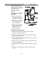
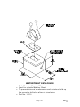
Destroy any previous versions of this manual!!!
Rev.A 8/99
MATHERS CONTROLS INC.
Technical Manual
Mathers ClearCommand MS546-11729
System Serial Number
3074
Destroy any previous versions of this manual!!!
Rev.A 8/99
Destroy any previous versions of this manual!!!
Mathers Controls Inc.
Technical Manual
August 1999
Vessel Specifications
Power:
Twin Screw
Cummins
Water Jet:
Hamilton
291 Jet Pump
Stations:
One Station
ClearCommand Specifications:
Control Processor
MS546-11729
System Serial Number: 3074
Sales Order Number
63316
Drawing Number
11228, 4 pages
Rev.A 8/99
Destroy any previous versions of this manual!!!
Rev.A 8/99
Destroy any previous versions of this manual!!!
Rev.A 8/99
TABLE OF CONTENTS
1. Theory of Operation ...............................................................1
1.1 This Manual........................................................................1
1.2 MS546-11729 ClearCommand System ....................................1
2. OPERATOR INSTRUCTIONS .....................................................2
2.1 DC Power On......................................................................2
2.2 Engine Start .......................................................................3
2.3 Control Head Tones .............................................................3
2.4 Water Jet Command ............................................................4
2.5 Throttle Command ..............................................................4
3. REQUIRED PARTS AND TOOLS.................................................4
3.1 Processor...........................................................................4
3.2 Control Head ......................................................................5
3.3 Electric Cable .....................................................................5
3.4 Tools Required For Installation ..............................................5
3.5 Engine Stop Switch..............................................................6
3.6 Control System Power..........................................................6
3.7 Push-Pull Cable...................................................................6
3.8 Hydraulic Servo Pressure Switch............................................7
4. PLAN THE INSTALLATION........................................................7
4.1 Control Processor Location....................................................7
4.2 Remote Control Head Location ..............................................8
4.3 DC Power Source (Refer to Figure 2) ......................................8
4.4 Hydraulic Servo Pressure Switch............................................9
5. INSTALLATION ......................................................................9
5.1 Eight-Conductor Cable .........................................................9
5.2 Processor...........................................................................9
5.2.1 Station Connection ....................................................... 10
5.2.2 Power Cable ................................................................ 11
5.2.3 Start Interlock ............................................................. 11
5.3 Control Heads................................................................... 13
Destroy any previous versions of this manual!!!
Rev.A 8/99
5.3.1 Install ........................................................................ 13
5.3.2 Cable Connection ......................................................... 13
5.4 Engine Stop Switch............................................................ 14
5.5 Hydraulic Servo Pressure Switch.......................................... 14
5.6 Push-Pull Cable................................................................. 14
6. ADJUSTMENTS and tests (secured to dock).............................. 16
6.1 Control Head (Engines Stopped) .......................................... 16
6.2 Water Jet Cable Adjustment (Engines Stopped)...................... 16
6.3 Water Jet Rate Adjustment (Engines Stopped) ....................... 18
6.4 Throttle Push-Pull Cable Adjustment (Engines Stopped) .......... 18
6.5 Start Interlock Test and Adjustments (Engines Stopped) ......... 19
6.6 Engine Stop Switches Test (Engines Running)........................ 20
7. Adjustments Underway......................................................... 20
7.1 Full-Speed Setting - Engine RPM.......................................... 20
8. CONTROL OPTIONS.............................................................. 21
8.1 Alarm Capability ............................................................... 21
9. MAINTENANCE .................................................................... 21
9.1 Control Processor .............................................................. 21
9.2 Control Head .................................................................... 21
Table of Figures
Figure 1 - Processor ................................................................... 4
Figure 2 - Power Source ............................................................. 6
Figure 3 - Processor Dimensions .................................................. 7
Figure 4 - Plug Removal and Cable Grip Installation .......................10
Figure 5 - Terminal Connection ...................................................10
Figure 6 - Start Interlock Connections ..........................................12
Figure 7 - Universal Mounting .....................................................14
Figure 8 - Push-Pull Cable Connection ..........................................15
Appendix A
Page ii
Destroy any previous versions of this manual!!!
Watertight Enclosure
Bonding
References
Parts Source
Checkout & Sea Trial Report
Appendix B
UE [H100 Series] Pressure Switch Data Sheet
Appendix C
Drawing. No. 11228, 4 pages
Page iii
Rev.A 8/99
Destroy any previous versions of this manual!!!
Page iv
Rev.A 8/99
Destroy any previous versions of this manual!!!
Rev.A 8/99
1. THEORY OF OPERATION
1.1 THIS MANUAL
The purpose of the ClearCommand System manual is:
Ø Operation
Ø Adjustments (Section 6)
Ø Trouble Shooting Reference
(Section 2)
Ø Installation
(Section 5)
(Appendix B)
Keep this Manual on the vessel for future reference.
Throughout the manual special attention should be paid to the
following boxes:
NOTE: Contains Helpful Information
CAUTION:
Disregarding these messages may cause damage to the equipment.
WARNING: Disregarding these messages may result in personal injury.
1.2 MS546-11729 CLEARCOMMAND SYSTEM
The Control Processor (hereafter referred to as Processor) is
designed specifically for:
Ø Mechanical command of Hamilton Water Jet
Ø Mechanical command of throttle
This system includes the following features:
Ø Station-in-Command
Indication (Section 2.1)
Ø Hydraulic Servo Pressure
Switch (Section 3.8)
Ø Start Interlock (option)
Ø ClearCommand Failure
Alarm Contact (optional)
(Section 2.2)
Ø ClearCommand System
Fault Indication (Section
(Section 8.1)
2.3)
System Requirements
(Refer to Section 3):
Ø One Dual lever Control
Head with no detents for
Ø One Dual lever Control Head
Engine Governor
with detents for Water Jet
command.
command.
Ø One Processor per engine
Page 1
Destroy any previous versions of this manual!!!
Rev.A 8/99
Ø One Engine Stop Switch per Ø One Two-conductor
remote station
electric cable for Start
Interlock connection
Ø Two Eight-conductor
Ø One Hydraulic Servo
electric cables for each
Pressure Switch per
Control Head
Processor
Ø One 33C push-pull cable for
each Water Jet connection. Ø One Two-conductor
electric cable per
Ø One 33C push-pull cable for
Hydraulic Servo Pressure
each Engine Governor
Switch for connection to
connection.
Processor
Ø One Two-conductor electric
cable for power connection
of the Processor
During Installation and Testing, take special care to verify all
wiring is to specifications, terminations are correct, and that all
Notes in Appendix C Drawing Notes are followed.
2. OPERATOR INSTRUCTIONS
2.1 DC POWER ON
When control system DC power is turned ON:
Ø Intermittent tone will sound at all remote stations
indicating that no station has command. (refer to Section 2.3)
To take command at a remote station:
Ø Water Jet Control Head lever may be in any position.
Ø Throttle Control Head lever must be in the Idle position.
Ø Operator must depress either the Water Jet or Throttle
Control Head station transfer button for at least 1/2
second.
The tone will stop at all remote stations and the red indicator
light on the Control Heads will be lit indicating station has taken
command.
Page 2
Destroy any previous versions of this manual!!!
Rev.A 8/99
2.2 ENGINE START
There are three features related to main engine start:
Start Interlock to block the engine start signal if the DC
power has not been turned ON.
Start Interlock to block the engine start signal if no station
has command.
Start Interlock to block the engine start signal if Throttle
Control Head lever is more than 10% of travel.
The engine Start signal will be connected through the Processor
to the starter solenoid or relay. Refer to Section 5.2.3 for Start
Interlock connection.
2.3 CONTROL HEAD TONES
Ø Low Repetition Rate Tone is normal when DC power is first
applied to ClearCommand. This tone indicates the Processor
is ready and the operator can take command at a remote
station.
If this tone occurs during operation, refer to Appendix B
Trouble Shooting Section.
Ø Steady Tone signals a voltage problem or a component has
failed. Confirm the voltage is steady between 12 and 24
volts DC, and that there is not a momentary voltage drop.
Ø Steady Tone may also occur if the cross-bar in the Processor
is unable to attain the Idle position.
If tone continues, refer to the Appendix B Trouble Shooting.
Ø Steady Tone is used to show a Throttle position feedback
error.
If tone continues, refer to the Appendix B Trouble Shooting.
Ø High Repetition Rate Tone is used to signal a jam condition of
the push-pull cable. The Processor has stopped when this
tone is heard. Moving the Control Head lever away from the
position that the tone was encountered will usually stop this
tone. The cause of the excessive push-pull cable load MUST
be found.
If tone continues, refer to the Appendix B Trouble Shooting.
Page 3
Destroy any previous versions of this manual!!!
Rev.A 8/99
2.4 WATER JET COMMAND
The Processor, on command from the Water Jet Control Head
lever, provides infinite position output to the Hamilton Water Jet
lever via push-pull cable connections.
On the Water Jet Control Head there is a detent at the vertical
position that corresponds to ZERO thrust. (Refer to System
Drawing in Appendix C) Thrust will correspond to Control Head
lever position command, regardless of how fast thrust is called
for.
A Normally Open (N.O.) pressure switch with a working
pressure rating greater than the relief valve settings on the
Water Jet System interlocks thrust command.
2.5 THROTTLE COMMAND
The Processor, on command from the Throttle Control Head
lever, provides control of speed that corresponds to Control
Head lever position via push-pull cable connections.
The Throttle Control Head’s Idle position is with the lever aft.
(Refer to System Drawing in Appendix C)
Forward movement of the Control Head Lever to the vertical
position corresponds to 50% throttle, with continued movement
forward to achieve 100% throttle.
3. REQUIRED PARTS AND TOOLS
3.1 PROCESSOR
Ø One Processor required per
engine (refer to Figure 1)
Ø Mounting Hardware is
installer supplied.
Ø Included with the Processor:
[ Wago Tool
[ Anti-Static Wrist Strap
10986
Figure 1 - Processor
[ Spare Fuse
Page 4
Destroy any previous versions of this manual!!!
Rev.A 8/99
3.2 CONTROL HEAD
Refer to Appendix C System Drawing for dimensional
information.
Ø Included with the Control Head:
[ Gasket
[ Terminals
[ Mounting screws
[ Watertight cable grip for the cable entrance on the Processors
[ Control Head Dimensions Variations & Installation Sheets
NOTE: Retrofit applications may require planning for an adapter pad to cover the
old Control Head cutout. A variety of adapter and cover pads are available
from Mathers Controls Inc.
3.3 ELECTRIC CABLE
Eight-Conductor
Cable (Control Head to Control Processor)
Shielded 20 AWG, 300V, PVC Insulated: -20 degrees C to +80 degrees C.
UL VW-1 PVC Jacket. Color Coded.
Two Conductor Power Cable
(Processor to DC Power Supply)
14 AWG, 300V, PVC Insulated: -20 degrees C to +105 degrees C
UL VW-1 PVC Jacket. Red with purple stripe and black.
Two Conductor Start Interlock Cable (Starter Switch to Processor
to Starter Solenoid)
16 AWG, 300 V, PVC Insulated: -20 degrees C to +105 degrees C
UL VW-1 PVC Jacket. Yellow with red stripe.
3.4 TOOLS REQUIRED FOR INSTALLATION
Ø Wago Tool (provided)
Ø Screwdriver –
Ø Anti-static Wrist Strap
Ø Screwdriver – med. straight slot
(provided)
Ø Screwdriver --
Ø Wire cutter (Recommend
med. Phillips #2
small straight slot
Ø Hole saw -- 1 inch
Thomas & Betts WT-2000)
Ø Drills -- 9/32 inch
Ø Wire stripper (Recommend
7/32 inch
Thomas & Betts WT-2000)
Ø Saw
Ø Wire crimper
(25,4mm)
(7,2mm)
and
(5,6mm)
(appropriate type of saw for
cutting material Control Head will be
mounted on)
(Recommend
Thomas & Betts WT-2000)
Page 5
Destroy any previous versions of this manual!!!
Rev.A 8/99
3.5 ENGINE STOP SWITCH
It is mandatory for an Engine Stop Switch to be located at each
remote station.
WARNING: An Engine Stop Switch at each station is an absolute requirement, and
will cancel warranty if not installed.
3.6 CONTROL SYSTEM POWER
The Processor requires
(Refer to Figure 2):
Ø A battery source of 12 or 24 volts DC
Ø A 10 ampere circuit breaker with manual reset
The power for the Control System should come from the same
power distribution panel as the other required engine functions.
(Refer to Appendix C Drawing Notes)
10460-0647
Figure 2 - Power Source
3.7 PUSH-PULL CABLE
Use Type 33C push-pull cable from the Processor to the
Hamilton Water Jet Gate levers. Hamilton recommends the
Morse 33C Supreme (low friction) cable. (Refer to the Hamilton
Jet Installation and Service Manual).
Use Type 33C push-pull cable from the Processor to the
engines.
Page 6
Destroy any previous versions of this manual!!!
Rev.A 8/99
When measuring cable length, measure cable from end of
thread to end of thread.
Many engines are delivered with factory push-pull cable
mounting kits. If mounting kit is not included, contact the
engine dealer for a Factory Cable Connection Kit or refer to the
Universal Mounting Figure in the Engine Push-Pull Cable
Installation Section of this manual.
3.8 HYDRAULIC SERVO PRESSURE SWITCH
The purpose of the Hydraulic Servo Pressure Switch is to inform
the Control Processor when hydraulic oil pressure is present.
The Processor will only control thrust when hydraulic pressure is
available. This switch must be used.
Refer to Appendix B - Manufacturer Data Sheets for information
on the switch.
4. PLAN THE INSTALLATION
4.1 CONTROL PROCESSOR LOCATION
Considerations:
10.71
Ø Refer to Figure 3 for
dimensions.
(272mm)
6.70
Ø The Processor is spray
proof but cannot be
immersed.
(170,2mm)
2.69
(68,3mm)
2.70
Ø Bulkhead mount preferred
for ease of access for
wiring and adjustments.
Mount the Processor in
any attitude easily
accessible for electric
connections. (See System
Drawing for mounting
dimensions.)
(68,6mm)
3.20
(81,3mm)
10.40
(264,2mm)
Ø Do not mount to the
engine, or transmission,
or any location that will
allow excessive vibration.
Page 7
4.75
(120,7mm)
10.25
11001-
(260.4mm)
Figure 3 - Processor Dimensions
Destroy any previous versions of this manual!!!
Rev.A 8/99
Ø ClearCommand uses electronic circuits that can be influenced
by strong magnetic fields, and static charges. Allow 4 feet
(1,2m) of clearance between the Processor and alternators or
electric motors.
Ø Locate away from heat sources, such as engine exhaust
manifolds.
Ø Mounting Hardware is installer supplied.
Ø Locate the Processor such that the push-pull cable to the
Engine and the push-pull cable to the Hamilton Jet Bucket
lever has large radius bends, with the least total degrees of
bend and moderate length.
NOTE: EXAMPLE: Minimum bend radius 10-inches (254mm) for total degrees of
bends of less than 270 degrees. Push-pull cable lengths should not exceed
20 feet (6m).
CAUTION:
It is mandatory the Processor power source is bonded (connected) to
the hull. See Section on Bonding.
4.2 REMOTE CONTROL HEAD LOCATION
Refer to Appendix C Control Head sheet for specific information
on a Control Heads.
When properly mounted on a console, the Control Head is
watertight from the top. An adhesive gasket must be used to
seal the Control Head to the mounting surface. However, below
the mounting surface the Control Head needs protection from
water or spray.
NOTE: If a Control Head is mounted weather exposed from the underside, consider
using a Watertight Enclosure. Reference Appendix A Watertight Enclosure
for specific information.
See Appendix C Control Head sheets for mounting dimensions.
4.3 DC POWER SOURCE (REFER TO FIGURE 2)
It is important to keep the length of power cable short to reduce
voltage drop. The power cable should not exceed 20 feet (6m).
If individual wires are used for supply (+) and return (-) then
the total wire length should not exceed 40 feet (12m).
Page 8
Destroy any previous versions of this manual!!!
CAUTION:
Rev.A 8/99
It is important that the wire size from the battery to the circuit breaker
panel is large enough to keep voltage drop due to current flow, to less
than 3 percent. The DC return to the battery must be large enough to
supply all current requirements with a voltage drop of less than 3
percent.
4.4 HYDRAULIC SERVO PRESSURE SWITCH
Refer to Appendix B - Manufacturers Data Sheets for specific
information relating to the pressure switch dimensions and
location requirements.
5. INSTALLATION
NOTE: Before starting the actual installation of ClearCommand, make sure you have
the correct parts and tools on hand. See Section 3. Read ALL the
instructions pertinent to each part before beginning the installation of that
part.
CAUTION:
Static electricity can destroy electronic components. Anytime the
Processor cover is off, use the anti-static wrist strap provided and
connect it to the Processor frame. This will drain any static charge you
may have on your person.
5.1 EIGHT-CONDUCTOR CABLE
A) Install the eight-conductor electric cable between each
Control Head and the appropriate Processor.
B) Label each eight-conductor cable at both ends with the
station it connects, and Port or Starboard for Twin Screw
applications.
When installing the eight-conductor cable, support the cables
using clamps or straps not more than 18 inches (0,5m) apart,
unless contained in a conduit.
Install each cable so it is protected from physical damage.
5.2 PROCESSOR
A) Secure the Processor using 1/4 inch or M6 fasteners.
B) Remove the Processor cover.
C) Connect the wrist strap to your person, and the ground
connector to the Processor frame.
CAUTION:
When not working on the Processor, keep the cover in place to prevent
damage to circuits.
Page 9
Destroy any previous versions of this manual!!!
Rev.A 8/99
D) Install the watertight cable grips needed for cable entrance.
Refer to Figure 4.
Start Interlock
Station 1
Processor
Watertight
Cable Grip
Nut
Gate Control
Servo
DC Power
Cable
Throttle
Servo
Body
Seal
Cable Grip
Body
Watertight
Cable Grip
Power
Cable Hole
Plug Entrance
11096-
Push
Figure 4 - Plug Removal and Cable Grip Installation
5.2.1 Station Connection
A) Insert cable through the appropriate watertight cable
grip.
B) Strip the PVC jacket and shielding back approximately
3 inches (75mm).
C) Stagger wire lead length to match the correct Station
terminal strip.
CAUTION:
Wire leads must not touch frame.
D) Strip the wire insulation 3/8inch (9,5mm) on each wire.
E) Locate the WAGO Tool that is
taped to the relay on the
circuit board in each
Processor. Use this tool to
depress the spring lock for
the individual wire
connections to the terminal
strip. (See Figure 5)
Page 10
Figure 5 - Terminal
Connection
Destroy any previous versions of this manual!!!
Rev.A 8/99
F) Connect colors to the station terminal strips as shown
on System Drawing in Appendix C.
G) Connect the shielding drain wire (bare wire) to
Terminal 8 on the station terminal strip.
CAUTION:
The shielding drain wire MUST NOT touch any other components.
H) Feed through a little slack cable, and tighten the cable
grip on the eight-conductor cable.
NOTE: Bring the other station's eight-conductor cables in the same way, and
connect to the appropriate station terminal strips. (Refer to Drawing in
Appendix C)
I) Tie wrap the station cable to the Processor frame.
CAUTION:
A jumper is required between terminals 5 and 6 on all unused station
terminals on the circuit board. Refer to Drawing Notes in Appendix C.
5.2.2 Power Cable
WARNING: When connecting the DC power cable to the Processor be sure the
power is OFF.
A) Run the length of two-conductor power cable between
the DC Power Supply and the Processor.
B) Install the power cable grip in the Processor enclosure.
(refer to Figure 4)
C) Connect the two-conductor cable to the Processor.
Refer to the Drawing in Appendix C for power
connection points.
D) Feed through a little slack cable and tighten the cable
grip.
E) Tie wrap the power cable to the Processor frame.
NOTE: Repeat for all Processors. Ensure all connections are as indicated on the
Drawing in Appendix C.
5.2.3 Start Interlock
CAUTION:
The Processor is designed for a maximum of 30 amperes, maximum 50
volt, start signal current. Greater current will damage the interlock
circuit.
Page 11
Destroy any previous versions of this manual!!!
Rev.A 8/99
Run the length of twoconductor start interlock
cable between the Starter
Solenoid and the
Processor. (Refer to
Figure 6)
Connections at Starter
Solenoid:
A) Remove the remote
start switch lead from
the Starter Solenoid.
B) Strip and connect one
start interlock cable
wire to this lead.
C) Strip and connect the
second start interlock
cable wire to the
Starter Solenoid
Figure 6 - Start Interlock
Connections
Connections at Processor:
A) Install the start interlock grip in the Processor
enclosure. (refer to Figure 4)
B) Run the two-conductor start interlock cable through
the watertight cable grip.
C) Strip insulation off of each wire 3/8-inch
install crimp terminals.
(9,5mm),
then
D) Connect the two-conductor cable as indicated on the
Drawing in Appendix C.
E) Feed through a little slack cable and tighten the cable
grip.
F) Tie wrap the start interlock cable to the Processor
frame.
Page 12
Destroy any previous versions of this manual!!!
CAUTION:
Rev.A 8/99
The most common source of trouble is loose wiring connections. Verify
wiring connectors are properly crimped and cannot be pulled out.
Crimps and connections must be made to the wire, not to the wire
insulation. Verify all screwed wire connections are secure.
5.3 CONTROL HEADS
See Appendix C Control Head sheet for location of cutout and
mounting holes for the Control Heads.
5.3.1 Install
A) Drill the screw holes and the corner cutout holes.
B) Saw between the corner cutout holes.
C) Check that the four mounting screws will start into the
Control Head.
D) Remove the Control Head.
E) Strip the adhesive cover from the gasket and apply the
adhesive side to the console.
5.3.2 Cable Connection
A) At the Control Head, strip back the PVC jacket on the
eight-conductor cable approximately 2-1/2 inches
(63,5mm).
B) Strip and cut off the shielding and drain wire flush with
the end of the PVC jacket.
CAUTION:
Do not connect the drain wire at the Control Head to ground.
C) Strip 3/8-inch (9,5mm) insulation off each wire, then install
crimp terminals.
CAUTION:
Connections 5 and 7 at the terminal block are direction sensitive. The
connections must be as follows:
Bucket Port Lever:
Terminal 5 Blue
Terminal 7 Yellow
Throttle Starboard Lever:
Terminal 5 Yellow
Terminal 7 Blue
D) Connect the Throttle Control Head and the Water Jet
Control Head as shown on the Appendix C – System
Drawing, Control Head Sheet.
Page 13
Destroy any previous versions of this manual!!!
Rev.A 8/99
5.4 ENGINE STOP SWITCH
The Installer supplies the Stop Switches. Refer to the
information supplied with the Stop Switches for installation
specifications.
WARNING:
Each remote station must have some method to stop the engine.
Warranty canceled if requirement not followed.
5.5 HYDRAULIC SERVO PRESSURE SWITCH
Locate the Hydraulic Servo Pressure Switch at a higher elevation
and within 5 feet of the Hamilton Jet Pump.
Refer to Appendix B - Manufacturers Data Sheets for specific
information relating to the pressure switch.
Refer to System Drawing for details on connection of the
pressure switch to the Processor.
5.6 PUSH-PULL CABLE
The Processor interconnects by push-pull cable with the engine
governor and the Jet Pump. The nominal load rating is 30
pounds force and 3 inches (76,2mm) maximum movement of the
push-pull cable.
WARNING: Take care to verify that push-pull cable installation is correct, as
misadjusted cables may cause damage to the engine governor and the
Jet Pump.
A) Verify installation
of push-pull cable
brackets on the
engine governor
and Jet Pump. If
the brackets are
not installed,
fabricate brackets
as shown in Figure
7
B) Remove the jam
nut and the two
rubber seals from
the push-pull
Fabricate
Bracket to match
dimensions shown
3/16" (4,8mm) Diameter
Push-Pull
Cable
TYP
7/32"
7-3/8" (187mm)
90
Shim
Cable Clamp 31638
31509
(5,8mm)
Diameter
1/4"
(6,4mm)
Diameter
Selector
Lever
Jam Nut
Ball Joint
2-3/4" (70mm)
31126 Maximum Movement
1" (25,4mm)
10246
1/4" - 28 UNF Stud
Figure 7 - Universal Mounting
Page 14
Destroy any previous versions of this manual!!!
Rev.A 8/99
cable end that is to connect to the Processor. Discard the
seals.
C) On the Processor housing, remove one screw from the cable
retainer clip for the cable.
D) Loosen the remaining screw and swing the cable retainer clip
away from the entry hole.
E) Insert the push-pull cables through the entry hole.
CAUTION:
Ensure that the push-pull cable for the engine enters the Processor
through the Throttle Servo opening. Ensure the Water Jet push-pull
cable enters the Gate Control Servo opening. Refer to Figure 4.
F) When the push-pull cable end is visible within the Processor
interior, reinstall the jam nut.
G) Connect the push-pull cable to the hex nut (See Figure 8,
Detail I). Use a 7/16-inch socket to turn the hex nut onto
the cable rod end until there is approximately 5/16 inch
(7,9mm) of thread showing beyond the jam nut.
Control Processor Housing
See Detail I
7/16" Socket
Jam Nut
Tighten
Hex
Nut
5/16"
(8mm)
Push-Pull Cable
(not Supplied)
1/4" Mounting Hardware
(not Supplied)
Detail I
0658
Figure 8 - Push-Pull Cable Connection
H) Tighten the jam nut to the hex nut.
I) Reinstall the cable retainer clip to secure the push-pull cable
to the Processor housing.
J) Do not connect the push-pull cable at the engine or the
Water Jet at this time.
Page 15
Destroy any previous versions of this manual!!!
Rev.A 8/99
6. ADJUSTMENTS AND TESTS (SECURED TO DOCK)
6.1 CONTROL HEAD (ENGINES STOPPED)
A) Turn the power ON to the control system.
WARNING: Keep hands and tools clear of the Processor when power is ON. Turn
OFF the control system power before disconnecting from the batteries.
Do not disconnect battery terminals when engine is operating.
B) The Control Head at each station will produce an intermittent
tone.
C) Take command at a remote station.
D) Move each Throttle Control Head lever from Idle to Full
Speed. Ensure the Port Processor reacts to Port lever
movement and the Starboard Processor reacts to the
Starboard lever.
NOTE: This will check that the Control Head lever is operating the correct
Processor. Push-pull cable direction will be tested later.
6.2 WATER JET CABLE ADJUSTMENT (ENGINES STOPPED)
NOTE: Hydraulic pressure MUST be available to move propeller.
A) Manually move the Jet Pump lever from the required Ahead
thrust to the required Astern thrust. Choose a radius on the
Jet Pump lever that will result in a push-pull cable movement
of greater than 2 inches (51mm) and less than 2.90 inches
(74mm).
B) Take command at the remote station.
C) Leave the Water Jet Control Head lever in the Zero Thrust
position.
D) Manually move the Jet Pump lever to the Zero Thrust
position.
E) Adjust the push-pull cable ball joint to match the Jet Pump
lever in the Zero Thrust position. Do not connect push-pull
cable to the Jet Pump lever at this time.
NOTE: The push-pull cable should form a right angle (90 degrees) with the Jet
Pump lever in the Zero Thrust position.
Page 16
Destroy any previous versions of this manual!!!
Rev.A 8/99
F) Manually move the Jet Pump lever to the Full-Ahead position.
G) Move the Water Jet Control Head Lever to Full-Ahead Thrust.
H) Verify the push-pull cable moves the correct direction to
move the Jet Pump lever to the Full-Ahead Thrust position.
Ø If correct, continue with the adjustments.
Ø If incorrect, change Jumper 4 on the Processor circuit
board to the correct direction setting. Refer to Appendix C
– System Drawing Notes.
I) Adjust trim pot R7 to match the push-pull cable to the Jet
Pump Full-Ahead Thrust position. Refer to Appendix C –
System Drawing for trim pot location.
NOTE: Before the Processors are shipped, the trim pots are set for minimum cable
movement.
J) When you have achieved the required movement for FullAhead thrust, then verify Full-Astern thrust.
Ø If Full-Astern is incorrect, a combination of Dip Switch
settings can be set to increase the portion of the cable
movement from Zero Thrust to Full-Ahead and decrease
movement Astern. Refer to Appendix C – System Drawing
Notes for Offset settings.
Ø If Full-Astern is correct, continue with the adjustments.
K) Verify all three positions; Full-Ahead Thrust; Zero Thrust;
and Full-Astern Thrust.
Ø If cable movement is correct at all three positions,
continue with the Adjustments and Tests.
Ø If cable travel is incorrect, review steps A) through K),
making the necessary adjustments.
L) Connect the thrust push-pull cable to the Jet Pump lever.
M) Confirm the Processor does not jam the Jet Pump lever
against its stops, and that Zero thrust is correct.
Ø If cable movement is correct at all three positions,
continue with the Adjustments and Tests.
Page 17
Destroy any previous versions of this manual!!!
Rev.A 8/99
Ø If cable travel is incorrect, the Processor jams the Jet
Pump lever against its stops, or Zero Thrust is incorrect,
review steps A) through M), making the necessary
adjustments.
6.3 WATER JET RATE ADJUSTMENT (ENGINES STOPPED)
NOTE: Hydraulic pressure MUST be available to command thrust.
A) Time how long it takes the Jet Pump lever to move it’s full
range by manually moving the Jet Pump lever.
B) A combination of Dip Switch settings adjust the thrust pushpull cable maximum travel time. Refer to the System
Drawing Notes for specific switch setting.
NOTE: Configure the Dip Switches to meet the closest time. If time cannot be
matched exactly, choose the setting the for the slightly slower time.
6.4 THROTTLE PUSH-PULL CABLE ADJUSTMENT (ENGINES STOPPED)
A) Locate trim pot R8 on the Processor Circuit Board.
B) Verify potentiometer R8 is fully in the counterclockwise
position, as shipped from the factory.
CAUTION: Turning too hard against the stop can damage Potentiometers.
B) Leave the throttle push-pull cable disconnected at this time.
C) Measure the throttle movement of the engine governor
selector lever from Idle to full-speed. It must be within the
Processor range of 2-inch (51mm) to 3-inches (76mm).
Ø If the throttle movement is less than 2-inch (51mm) or
greater than 3-inches (76mm), the lever radius must be
changed to be within range.
Ø If possible, throttle movement should be 2-1/2-inches
(64mm) from Idle to full-speed.
D) Ensure engines are stopped.
E) Take command at the remote station.
F) Manually move the throttle selector lever on the governor to
the Idle position.
Page 18
Destroy any previous versions of this manual!!!
Rev.A 8/99
G) Move the Throttle Control Head lever from Idle to full-speed.
Verify the throttle push-pull cable moves the correct direction
to move the engine governor selector lever to the full speed
position.
Ø If correct, continue with the adjustments.
Ø If incorrect, change Jumper 3 on the Processor circuit
board to the correct setting. Refer to Appendix C –
System Drawing Notes.
H) Place the Throttle Control Head lever to the Idle position.
I) Manually move the engine throttle lever to the Idle-speed
stop.
J) Adjust the throttle cable ball joint at the engine to match the
throttle selector lever at the Idle position.
K) Leave the cable disconnected at this time.
L) Place the Throttle Control Head lever to the full-speed
position.
M) Manually move the engine throttle lever to the full-speed
position.
N) Gradually turn potentiometer R8 on the circuit board
clockwise until the push-pull cable ball joint, when
connected, will exert a slight amount of pressure against the
full-speed throttle stop.
O) Recheck from Idle to full-speed.
Ø If incorrect, repeat step F) through N) until correct.
Ø If correct, connect the push-pull cable ball joint to the
throttle selector lever.
6.5 START INTERLOCK TEST AND ADJUSTMENTS (ENGINES
STOPPED)
NOTE: If any of the following tests fail, verify Start Interlock Installation and Start
Interlock connections as shown on the Drawing in Appendix C and in Figure
6.
A) Turn the ClearCommand DC power OFF.
Page 19
Destroy any previous versions of this manual!!!
Rev.A 8/99
B) Verify that the engine(s) will not start.
C) Turn the ClearCommand DC power ON.
D) Accept command at the remote station.
E) Place the Throttle Control Head Lever to 50% speed.
F) Verify engine(s) will not start.
G) Place Throttle Control Head Lever in the Idle position.
H) Verify engine(s) will start in this position.
6.6 ENGINE STOP SWITCHES TEST (ENGINES RUNNING)
A) Start engine(s).
B) Verify that all Engine Stop Switches function correctly at all
stations.
Refer to information supplied by engine manufacturer or switch
supplier for set-up and adjustments.
CAUTION:
An Engine Stop Switch at each station is an absolute requirement, and
will cancel warranty if not installed.
WARNING: Do not attempt to continue tests until Engine Stop Switches function
correctly.
7. ADJUSTMENTS UNDERWAY
WARNING: DO NOT attempt to operate ClearCommand away from the dock with any
system abnormality. Verify that all the above tests are completed and
are correct.
CAUTION:
Start slowly and learn to appreciate that the ClearCommand System
provides a light touch that is fast and accurate.
7.1 FULL-SPEED SETTING - ENGINE RPM
In open water gradually move the Throttle Control Head Lever
to full-speed. Engine(s) should be running at full rated RPM.
Consult the engine operator's manual for additional RPM
adjustments.
Page 20
Destroy any previous versions of this manual!!!
Rev.A 8/99
8. CONTROL OPTIONS
8.1 ALARM CAPABILITY
ClearCommand offers a single alarm connection that OPENS
with a system power failure or circuit malfunction.
The Processor's alarm connection point is a single connection
block on each Processor Circuit Board. The alarm circuit in the
Processor operates an alarm system supplied by others.
The control failure alarm is rated for a maximum of 200 mA. Do
not exceed this rating. Normal operation is 21 ohms to DC
return, high impedance indicates Alarm Condition.
It is the Shipyard’s responsibility to utilize the alarm connection
in an appropriate alarm circuit that has the same common mode
voltage.
9. MAINTENANCE
9.1 CONTROL PROCESSOR
The ClearCommand Processor requires the following annual
checks:
Ø Check all terminal connections for signs of corrosion or loose
connections.
Ø Check mechanical connections within the Processor, and at the
engine and Water Jet System.
Ø Check mechanical movement of the selector levers. Ensure that the
push-pull cable does not jam.
Ø Cycle the Processor and if lead screws are noisy, apply a light
coating of silicone grease to the stainless steel lead screw.
9.2 CONTROL HEAD
Verify once a year that Control Head terminals are secure and
free of corrosion. Apply a light coating of Teflon grease, or
corrosion block, to the contacts.
Page 21
Destroy any previous versions of this manual!!!
Page 22
Rev.A 8/99
Appendix A
Table of Contents
WATERTIGHT ENCLOSURE ......................................................... 3
BONDING
A.B.Y.C. 46 CFR 111.05 ........................................... 5
REFERENCES ........................................................................... 7
PARTS SOURCE ........................................................................ 8
CHECKOUT & SEA TRIAL REPORT ................................................ 9
WATERTIGHT ENCLOSURE
•
•
•
•
Deck Mount or Exposed Mount
Ideal for outside Weather Mount
To prevent internal condensation and moisture build up
the mount is drilled to allow air circulation.
Part No. 12110
Page 1 of 1
MMC-279
1/97
BONDING
A.B.Y.C. 46 CFR 111.05
All boats equipped with a permanently installed electrical system
shall also be equipped with a bonding system. The negative
terminal of all batteries should be connected at only one point, the
DC common, and from DC common to bond system or hull.
Metal - Hull Vessels
The hull of a metal - hull vessel may serve as the common bonding
conductor. Any item to be bonded not in contact with the hull
requires a bonding conductor to the hull.
Page 13
Page 14
REFERENCES
AMERICAN BOAT & YACHT COUNCIL
(ABYC)
Box 806
Amityville, NY 11701
E-1 Bonding of Direct Current Systems
E-3 Wiring Identification on Boats
E-9 DC Electrical Systems on Boats
H-2.4e or 32.4g Ambient Temp. 50 degrees C
CODE OF FEDERAL REGULATIONS
33
33
33
33
33
33
33
46
CFR 183 Subpart I - Electrical Systems
CFR 183, 410 Ignition protection
CFR 183, 415 Grounding
CFR 183, 425 Conductors: General
CFR 183, 430 Conductors in circuit of less than 50 Volts
CFR 183, 445 Conductors: Protection
CFR 183, 455 Over-current and Protection: General
CFR 111.01 - 15(b) Ambient Temp.
Machinery Spaces 50 degrees C
46 CFR 111.05- System Grounds
SOCIETY OF AUTOMOTIVE ENGINEERS
400 Commonwealth Drive
Warrendale, PA 15096
J1171 External Ignition Protection
J1428 Marine Circuit Breakers
J378 Marine Engine Wiring
NATIONAL MARINE MANUFACTURERS ASSOCIATION
401 North Michigan Avenue
Chicago, IL 60611
UNDERWRITERS LABORATORIES
Page 15
PARTS SOURCE
Anti-Static Wrist Strap Part No. 517
Fuse
Part No. 1030
WAGO Tool
Part No. 397
Page 16
[Thomas & Betts (Part No. AWCC)]
[Bussman (Part No. GDC-1A)]
[WAGO (Part No. 236-332)]
MicroCommander/ClearCommand
Checkout &Trial Report
Vessel Name:
Mathers Controls, Inc.
675 Pease Road
Burlington WA 98233-3103
U.S.A.
Tel: 360-757-6265
Fax: 360-757-2500
e-mail: [email protected]
ClearCommand SSN:
Trial Date:
Owners Name:
Address:
Tel/Fax/e-mail:
Contact Name:
APPLICATION:
A: Boat Builder
Model
Original Equipment
Retrofit
Size
Year
Type of Controls Replaced
B: Single or Twin Screw
Engine Make
Model
Horsepower
RPM
Engine Hours
Reduction Gear/Drive
Model/Ratio
Trolling? Yes
Type of Service (Pleasure, Fishing, Rental, Etc)
C: Number of Control of Stations
Port Actuator/Control
Starboard Actuator/
S/N
Processor: Model
Trolling Actuator:
Model
S/N
Control Processor: Model
S/N
Synchronizer: Yes
Type of Input Signal (tach gen, mag pick-up, etc.)
No
Control Station Location(s) and Model(s)
Before Running Engine:
Port
Stbd
1. Voltage at the Battery Terminals.
VDC
VDC
2. Voltage at the Actuator/Control Processor.
VDC
VDC
3. Warm-up Indicator Light blinks in 'Ahead'. All Stations.
Yes
No
Yes
No
4. Electric Cables are supported every 18 inches.
Yes
No
Yes
No
5. Cable connections are tight at the Actuator/Control Processor and
Control Heads.
Yes
No
Yes
No
6. Engine Shutdown
operational.
Yes
No
Yes
No
Yes
No
Yes
No
Switches
at
EACH
Remote
Station
are
7. Check push-pull cable match. Disconnect push-pull cables at the
clutch and throttle. Check that cables travel in the correct
direction. Check the cable movement, insure that it matches
clutch and throttle.
F-226 Rev1/99
No
Port
Dock Side Tests (Running):
1. Voltage at the Battery Terminals.
Stbd
VDC
2. Does Engine 'Start' when Controls are 'OFF'?
3. Low Idle RPM.
Yes
No
RPM
4. High Idle RPM (optional).
RPM
VDC
Yes
No
RPM
RPM
5. Check Warm-Up Mode.
Yes
No
Yes
No
6. Check shift in both directions.
Yes
No
Yes
No
Sea Trials:
Port
1. Check that Twin Screw
throughout speed range.
Levers
match
position
and
RPM
Yes
Stbd
No
Yes
No
2. Set maximum engine RPM as required.
RPM
RPM
3. Adjust Full Speed Reversal Delay.
SEC.
SEC.
4. Is Synchronizer operational?
Yes
No
Yes
No
5. Is Trolling Valve operational?
Yes
No
Yes
No
5
6
SW 1 Switch Settings:
1
2
PORT
3
4
5
6
7
1
ON
ON
OFF
OFF
PORT
JMPR 3
JMPR 4
STBD
PUSH
PUSH
PULL
2
JMPR 3
JMPR 4
PULL
STBD
3
4
PUSH
PULL
PUSH
PULL
Comments (Please use additional paper as necessary):
General Installation Condition:
Any Irregularities:
ARE THE MANUALS ON BOARD?
Yes
IS THE OPERATOR CARD ON BOARD?
INSPECTOR
MAIL COMPLETED COPY TO:
Mathers Controls Inc.
675 Pease Road
Burlington, WA 98233
No
Yes
No
DATE
OR FAX TO:
360-757-2500
F-226 Rev1/99
7
Appendix B
Appendix C


![3830 - SO02471 [96202 SW15623_0H Dwg13068A] Donovan](http://vs1.manualzilla.com/store/data/005999028_1-10b082f35c5d7c0c53e968105ce08056-150x150.png)