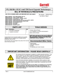
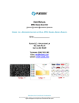
1
Ford Mustang GT - Garrett Tuner Turbo Kit
Bill of Materials & Precautions
Ford Mustang GT Twin Turbo
Part Number: 768674-0001
4.6l V8
Parts List
Item
Required Other Items
Qty
Description
1
2
3
4
5
6
7
8
Exhaust Manifold R (765380-0004)
1
Exhaust manifold L (765382-0004)
1
Fluid line Kit (779931-0001)
1
Gasket kit (716909-0046)
2
Left Downpipe Upper (774802-0001)
9
Turbo Assy (739548-5001s)
10
Fastener Kit (769959-0001)
1
1
1
2
1
11
Installation Instructions (737639-0033)
1
Left Downpipe Lower (777849-0001)
Right Downpipe (765386-0001)
•Hi Volume Fuel Pump (we used Ford Racing P/N M-9407-GT05)
•Hi Flow Fuel Injectors (We used Ford Racing 42lb/hr)
•Ford Exhaust Pipe Studs (Ford P/N W707747S431)
•Ford Exhaust Gasket (4 req’d) (Ford P/N 3L329448A)
•Proper Heat Range Spark Plugs (We used Autolite HT)
•Battery Relocation Kit (We used Summit SUM-G1231-K)
•MAF Sensor (We used PMAS- 30T)
•ECU Tuning Device (We used SCT Livewire)
•Tial Blow-off Valve
• NOTE: This is not meant to be an endorsement of
the above brands or products and no claims of
suitability are made.
Recommended Other Items
•
•
•
•
•
•
•
Factory Service Manual
Safety glasses
Catch basins for engine coolant and engine oil
Engine coolant (quantity per service manual)
Anti-seize compound
Oil filter
Oil (quantity per service manual)
IMPORTANT INFORMATION - PLEASE READ CAREFULLY
We recommend that this turbo kit be installed by a qualified automotive technician. If you have
any doubts as to your ability to install this turbo upgrade kit, consult with a local automotive
repair company. Please be sure to carefully read all of the attached instructions prior to
starting the installation process. If you have any questions about the enclosed parts or the
instructions, call the distributor that you purchased the kit from for clarification.
Prior to the Garrett Turbo Kit installation, be sure that the vehicle is parked on a level surface
and the engine is cool. Engine fluids and components can be extremely hot following normal
vehicle operation. Avoid direct contact of engine fluids or components with your skin which
may cause personal injury.
NOTE: It is recommended that the oil and oil filter are changed prior to running the
Garrett turbocharger. This will provide clean oil to the new turbocharger. To
ensure optimal performance, always follow oil and filter change intervals per the
Factory Service Manual.
Doc. 737639-29 (Rev A)
www.TurboByGarrett.com
1
Chevrolet Cobalt – Garrett Alpha Turbo Kit
Part Number: 766621-0001
IMPORTANT INFORMATION - PLEASE READ CAREFULLY
Return Policy
Only unused and complete merchandise will be accepted for return subject to inspection and
acceptance by Honeywell Turbo Technologies. No goods will be accepted without prior return
authorization from Honeywell Turbo Technologies. No returns are accepted after thirty (30) days
from original ship date from The Garrett Garage. All accepted returns are subject to a 20%
restocking charge - NO EXCEPTIONS.
Damaged Shipments
The customer must file a claim with the shipping company if goods arrive in a damaged condition.
The customer must also notify Honeywell Turbo Technologies with pertinent information.
Refused Shipments
Sending a shipment back to The Garrett Garage (or Honeywell) does not automatically give rise to a
complete refund or credit. Honeywell Turbo Technologies may, at its sole discretion require different
payment means for any shipment refused and then reshipped. It is the customer’s responsibility to
make all arrangements with Honeywell Turbo Technologies for disposition of refused shipments.
Shortage or Discrepancy Claim
Shortage or Discrepancy claims must be reported within forty-eight (48) hours of receipt of goods.
Honeywell Turbo Technologies will either issue a credit or send a replacement(s) at no charge.
Please contact [email protected] for instructions on how to address shortages or
discrepancies.
Limited Warranty
Honeywell Turbo Technologies warrants to the original purchaser of its Turbocharger Products that
such Turbocharger Products will, for a period of 1 year from date of shipment and subject to the
Limitations on Warranty, be free from defects in materials and workmanship. For approved warranty
claims Honeywell Turbo Technologies will, at its sole discretion, either credit the original purchaser
in an amount equal to the original purchase price, or replace the applicable Turbocharger Product
free of charge, within 60 days of Honeywell Turbo Technologies’ approval. This is purchaser’s sole
and exclusive remedy and provides the complete financial responsibility of Honeywell Turbo
Technologies for a warranty claim.
To be eligible for reimbursement, Customer must (a) submit all warranty claims to Honeywell Turbo
Technologies within 30 days of the discovery of the alleged Turbocharger Product defect; and (b)
complete and return a Returned Material Authorization Form. This form may be obtained from
Honeywell Turbo Technologies at [email protected].
When Honeywell Turbo Technologies requires the examination of a failed part, Honeywell Turbo
Technologies will promptly notify Customer and will await receipt of the failed part before further
processing the warranty claim. If Honeywell Turbo Technologies ultimately determines that the
failed part is covered under the Limited Warranty, Honeywell Turbo Technologies will reimburse
Customer for the actual cost of ground shipment for any part found to be defective.
Doc. 737639-29 (Rev A)
www.TurboByGarrett.com
2
Chevrolet Cobalt – Garrett Alpha Turbo Kit
Part Number: 766621-0001
IMPORTANT INFORMATION - PLEASE READ CAREFULLY
Limitations on Warranty
The Limited Warranty does not apply to any parts: (a) not used in accordance with Honeywell Turbo
Technologies’ written instructions (b) for which no fault is found; (c) that have been modified in any
manner not specifically approved by Honeywell Turbo Technologies; (d) for which an inspection
indicates that reasonable and proper installation and/or preventative care and maintenance has not
occurred; (e) that have been subject to damage attributable to or caused by misuse, abuse or
vandalism; mishandling, improper shipping or other transit related damage; acts of god or
insurrection; foreign object entry; any part not supplied by Honeywell Turbo Technologies; any repair,
maintenance or service by anyone other than Honeywell Turbo Technologies; or any other acts that
are beyond Honeywell Turbo Technologies’ reasonable control; or (f) attributable to parts not
supplied by Honeywell Turbo Technologies. Honeywell Turbo Technologies expressly disclaims any
and all warranties relative to the foregoing circumstances.
Honeywell Turbo Technologies shall not be liable to Customer under any circumstances for
any special, incidental or consequential damages, including without limitation, damage to or
loss of property other than for Turbocharger Products; damages incurred in installation,
repair or replacement; lost profits, revenue or opportunity; loss of use; losses resulting from
or related to downtime of Turbocharger Products; the cost of replacement transportation,
power, or compression; the cost of substitute products; or claims of third parties for such
damages, howsoever caused, and whether based on warranty, contract, and/or tort (including
negligence, strict liability or otherwise).
The Limited Warranty is the only warranty made by Honeywell Turbo Technologies for any of
its turbochargers and related parts and/or services, and is in lieu of and excludes all other
warranties, expressed or implied, including warranties of merchantability or fitness for a
particular purpose. Honeywell Turbo Technologies hereby disclaims all other warranties not
expressly set forth. Some jurisdictions do not allow for the exclusion of implied warranties, so
the above exclusions may not apply to you, however if implied warranties do apply they are
limited to the original purchaser and for a period of one (1) year from the date of shipment.
Diagnosing Your Vehicle
Do not rely on diagnostic software without seeking the advice of an ASE certified mechanic.
Diagnostic software should only be used as a general guideline to help you facilitate the repair of
your car. If you experience or suspect any malfunction of vital safety equipment, such as your brakes,
exhaust, motor, transmission, fuel delivery system, your car’s structural integrity or any other
potentially life threatening malfunction, cease driving your vehicle immediately and seek professional
help. Always consult your owner’s manual.
Vehicle Modification Notice
Any modifications to your car are AT YOUR OWN RISK. You should consult the owner’s manual and
service manual. You should also contact your car’s manufacturer to determine what effects
modifications may have on your safety, warranty, performance, etc. Please also contact your local
authorities to determine whether your intended modifications will make your car illegal to drive on
public roads. A vehicle modified by the use of competition parts may not meet the legal requirement
for use on public roads. It is your responsibility to comply with federal, state, and local laws prior to
driving your vehicle on public roads.
Doc. 737639-29 (Rev A)
www.TurboByGarrett.com
3
Chevrolet Cobalt – Garrett Alpha Turbo Kit
Part Number: 766621-0001
IMPORTANT INFORMATION - PLEASE READ CAREFULLY
ECU Reprogramming Notice
Turbocharger Kits require that the Vehicle’s Engine Control Unit (ECU) be reprogrammed before
operation. Failure to properly recalibrate the operating parameters can result in severe engine
damage.
TUNER KIT
This kit is sold as a “tuner kit”, meaning that some further fitment and fabrication is required to
complete the installation. This is done to allow maximum flexibility for the installer to optimize the kit
to meet the customer’s requirements. Depending on how the kit is to be customized, some of the
installation steps in this document may need to be completed in a different order, deleted, or new
steps added to complete the installation. These instructions are intended only a guide to assist the
mechanic’s judgment.
OTHER PRECAUTIONS
Observe all safety precautions and warnings contained in the installation instructions. Wear eye and
ear protection and appropriate protective clothing. When working under or around the vehicle support
it securely with jack stands. Use only the proper tools. Exercise extreme caution when working with
flammable, corrosive, and hazardous liquids and materials.
LEGAL INFORMATION
The Garrett turbo kits are for use off the public roadways. Federal law restricts the removal or
modification of any part of a federally required emission control system on motor vehicles. Also,
many states have enacted laws which prohibit tampering with or modifying emission or noise control
systems. Vehicles which are not operated on public roadways may be exempt from certain
regulations, however the buyer is strongly urged to check all applicable local and state laws and is
ultimately responsible for compliance with the applicable laws and regulations.
Honeywell Turbo Technologies Contact Information
Please contact Honeywell Turbo Technologies at [email protected] for any questions
regarding this Shipping/Returns/Cancellation Policy, for notifications to Honeywell Turbo
Technologies, and for instructions on processing damaged shipments and authorized returns.
Honeywell Turbo Technologies
Garrett Independent Aftermarket
Honeywell International Inc.
3201 W. Lomita Blvd.
Torrance, CA 90505
www.TurboByGarrett.com
Doc. 737639-29 (Rev A)
www.TurboByGarrett.com
4
Ford Mustang GT – Garrett Tuner Turbo Kit
Part Number: 768674-0001
Installation Instructions
Battery
1. Remove the battery and battery tray –
(Fig.1) Disconnect the negative lead first,
then the Positive lead. Remove the battery
heat shield. Remove the bolt and battery
hold down clamp and remove battery.
Remove 3 bolts and the battery tray.
Relocate the battery to the trunk using a
Battery Relocation Kit.
2. Drain oil and water – drain the engine oil and
engine coolant.
3. Remove the Air Filter Assy – Disconnect the
crankcase vent tube (Fig. 2) from the intake
air duct. Loosen the 2 clamps and remove
the intake air duct. Disconnect the mass air
flow (MAF) sensor electrical connector (Fig.
3). Remove the air cleaner assembly bolt and
gently pull the air filter assy from the vehicle.
CAUTION: COVER THE THROTTLE BODY
WITH A RAG TO KEEP FOREIGN OBJECTS
OUT!
Fig.1
Vent Tube
Fig.2
MAF Sensor
4. Remove the Exhaust Manifolds - PERFORM
THE FOLLOWING WORK ON A COLD
VEHICLE ONLY
a.
Raise and support vehicle. The use of a floor
hoist is recommended. If you do not have
access to one, use a hydraulic floor jack and
jack stands to raise and support the vehicle.
a.
Caution: Jack stands must be
used on a level surface and be
securely seated. Failure to do
so may result in personal injury
or vehicle damage.
b.
Disconnect the oxygen sensor and wiring
retainer (1 per side).
c.
Disconnect Catalyst Monitor Sensors located
on the catalytic converter (1 per side).
Doc. 737639-29 (Rev A)
Fig.3
www.TurboByGarrett.com
5
Part Number: 768674-0001
Ford Mustang GT – Garrett Tuner Turbo Kit
Installation Instructions
d.
Remove exhaust manifold to H-pipe nuts (2 per side).
e.
Loosen exhaust coupler clamps located between H-pipe and tailpipe.
f.
Remove lower exhaust manifold nuts and studs (4 per side accessible from
underneath).
g.
Remove H-pipe.
h.
Remove steering column pinch bolt at rack and disconnect the steering coupling.
DO NOT ALLOW THE STEERING WHEEL TO ROTATE WHILE THE STEERING
COLUMN INTERMEDIATE SHAFT IS DISCONNECTED OR DAMAGE TO THE
CLOCKSPRING CAN RESULT.
i.
Remove dipstick and tube from the drivers side of the engine by removing one
bolt on the cylinder head.
j.
Remove upper exhaust manifold nuts and studs (4 per side).
k.
Remove the exhaust manifolds from below.
l.
Remove the oxygen sensor from the drivers side exhaust manifold. Set it aside, it
will be re-installed in step 7.c.4.
m.
Install Garrett manifolds with new exhaust gaskets. Install
exhaust studs and nuts and torque to
34Nm (25 lb-ft) (8 per side). On the driver’s side, it will be
necessary to trim the upper front stud by 1/4” (6mm) to
clear the manifold (Fig. 4).
n.
o.
p.
Shorten this stud
Install the dipstick and tube, and torque the bolt to 9Nm (80 lb-in).
Fig.4
Install steering column on rack and tighten pinch bolt to 25Nm (18 lb-ft).
Install the manifold support brackets as shown (Fig. 5a&b). Attach each bracket to
the manifold with an included M8 x 12 6-point bolt at one end and with an existing
fastener on the block at the other end. Torque the manifold bolt to 25Nm (18 lbft) and the existing fastener to 12Nm (100 lb-in)
Support
bracket
Driver-side
Passenger-side
Fig.5a
Doc. 737639-29 (Rev A)
Fig.5b
www.TurboByGarrett.com
6
Ford Mustang GT – Garrett Tuner Turbo Kit
Part Number: 768674-0001
Installation Instructions
5. Turbocharger Preparation –
•
a.
Test fit the turbos to the manifolds to determine
the proper compressor and turbine orientation.
Orientation can be adjusted by loosening the
clamp bolts that hold the compressor and
turbine housings to the center housing and
rotating the housing to the desired location. The
center housing oil drain must point down. Use
the supplied adjustable actuator brackets and
rod ends to position the actuator so that the
actuator rod lines up with the wastegate crank
and does not rub the lower actuator
housing during operation (Fig 6).
Prepare the turbos for installation – install the
oil inlet fitting, the oil drain fitting, water inlet
fitting, heat shield bracket and the down pipe
prior to installing the turbocharger (Figure 7):
No Rub here
Fig.6
Oil Inlet fitting
Water
fittings
Heat Shield
Bracket
1) On both turbos install the -3 oil inlet fitting.
2) On both turbos install the water inlet and
outlet fittings with the supplied copper crush
washer.
Fig.7
3. On both turbos install the oil drain fitting
using the two (2) 12-point bolts supplied
(Fig. 8). Make sure the o-ring is in place.
A spare o-ring is provided in the gasket kit.
4) On both turbos install the heat shield
bracket by removing the turbine housing
bolt pictured. Install the bracket and torque
the bolt to 200 lbf-in.
5) On the passenger-side turbo install two (2)
M8 studs in the turbine housing outlet flange
as shown (Fig. 9a).
Oil drain flange
Fig.8
Passenger-side studs
6) On the driver-side turbo, install one (1) M8
stud in the turbine housing outlet flange as
shown. (Fig. 9b) (next page)
Fig.9a
Doc. 737639-29 (Rev A)
www.TurboByGarrett.com
7
Part Number: 768674-0001
Ford Mustang GT – Garrett Tuner Turbo Kit
Installation Instructions
6. Install and route the oil and water lines –
a.
Oil Supply:
Driver-side stud
1. Disconnect the engine oil pressure sensor
electrical connector located on the oil filter
adapter.
2. Remove the oil pressure sensor and clean
any sealant from the threads.
3. Take the supplied multi-port oil feed fitting
and, using a light coating of thread sealant
paste on the threads, thread it into the
pressure sensor port and torque to 20Nm
(15lb-ft). Mark the two most accessible holes
with a marker. You may need to turn the
fitting slightly one way or the other to get
two holes to be optimally positioned.
Fig.9b
Unmarked
holes with
plugs
installed
Oil
Pressure
sensor
goes
here
4. Now remove the fitting and install the four
supplied plugs into the holes without the
marks. Re-install the multi port oil feed fitting
and tighten to the same position as in the
previous step.
Marked
holes with
fittings
installed
5. Install the two supplied -3 fittings into the
two marked holes, and torque to 20Nm
(15lb-ft). (Fig 10)
6. Apply new thread sealant paste to the
threads and install the oil pressure sensor
into the multi-port hole and, holding the
multi-port fitting to prevent it from moving,
torque the oil pressure sensor to 20Nm (15lbft) (sensor connector may need to be
modified to fit) .
b.
Coolant Supply: Remove the plug on the
block (driver’s side rear). Trapped coolant in
the block will drain out. Apply thread sealant
to the adapter and install as shown. Tighten
to 25Nm (20lb-ft). Now fit the Tee swivel
fitting and position the fitting as shown (Fig.
11) and torque to 25Nm (20 lb-ft).
Doc. 737639-29 (Rev A)
www.TurboByGarrett.com
Fig.10
Block plug
location
Adapter
and Tee
fitting
installed
Fig.11
8
Part Number: 768674-0001
Ford Mustang GT – Garrett Tuner Turbo Kit
Installation Instructions
c.
Coolant Return: Remove the plug on the
intake manifold water passage (Fig. 12) and
install the supplied banjo fitting, crush
washers, and bolt. Position as shown (Fig.
13) and torque to 67Nm (50lb-ft).
d.
Oil Drain: This step will require removal of
the oil pan and will be covered later in step
10.b.
Remove this plug
Fig.12
Banjo fitting and bolt installed
e.
Oil Feed Hose Routing
1. Passenger-side turbo: Take the longest
supplied steel braided hose and attach to
the multi-port oil feed fitting as shown (Fig.
14). Route along lower block and shown
(Fig 15 & 16).
2. Drivers-side turbo: Using the shorter
supplied steel braided hose, route as shown
(Fig. 15).
Fig.13
*Use supplied clamps and be sure to
carefully route the lines. The braided
stainless line is very abrasive and will quickly
wear through anything it is allowed to rub
against.
Passenger-side
feed line
Driver-side
feed line
Fig.14
Passenger-side oil
feed
Passenger-side oil
feed (back of block)
Fig.16
Doc. 737639-29 (Rev A)
Driver-side oil feed
(shown alongside
coolant line).
Fig.15
www.TurboByGarrett.com
9
Ford Mustang GT – Garrett Tuner Turbo Kit
Part Number: 768674-0001
Installation Instructions
7. Mounting the Turbochargers –
a.
For both turbos: Install four (4) M8 studs on
the turbine inlet flange of each manifold .
Place the turbine inlet metal gasket on the
exhaust manifold studs. Install the
turbocharger and drop it onto the studs.
Start all four (4) nuts before tightening any
of them. Tighten all nuts to 25Nm (18 lb-ft).
(it may be helpful to temporarily remove the
compressor housing to access difficult to
reach fasteners. Be careful to prevent
damage to the exposed compressor wheel
blades)
8. Mounting the Downpipes a.
For the passenger-side turbo:
1. Fit an exhaust flange gasket over the studs
on the turbine housing. Take the cast
downpipe and pass it down along the firewall
and fit the slots in the flange over the studs
mounted in the turbine housing. Install M8
nuts on the studs and M8 bolts in the
remaining three (3) holes. Tighten all
fasteners to 25Nm (18 lb-ft).
2. From below, install the exhaust pipe studs
into the downpipe exhaust flange Tighten
studs to 45Nm (33 lb-ft).
c.
For the driver-side turbo:
1. Fit an exhaust flange gasket over the stud
on the turbine housing. The driver-side
downpipe is a 2-piece fabricated tube (upper
downpipe and lower downpipe) held together
with a spherical clamp. Before getting
started, install the exhaust pipe studs into
the lower downpipe exhaust flange and
tighten studs to 45Nm (33 lb-ft).
Doc. 737639-29 (Rev A)
www.TurboByGarrett.com
10
Ford Mustang GT – Garrett Tuner Turbo Kit
Part Number: 768674-0001
Installation Instructions
d.
Move and/or relocate any tubing or
components on the driver-side of the engine
bay to gain clear access for the downpipe
installation.
e.
With a twisting motion feed the lower
downpipe towards the bottom of the engine
bay towards the exhaust pipe.
f.
Install the O2 sensor that was removed in
step 4-m. Tighten to 48Nm (35 lb-ft).
g.
Install the H-pipe and slide clamps into place,
but do not tighten yet.
h.
Fit the lower downpipe exhaust flange studs
into the exhaust pipe and start the nuts on
the threads, but do not tighten. This will help
to align the lower down pipe properly. Slide
the spherical joint clamp over the spherical
flange, leaving the clamp loose.
i.
Install the upper downpipe onto the single
stud on the turbine housing outlet flange,
making sure that the gasket is in place.
Thread on a nut and use bolts in the other 4
holes and tighten to 25Nm (18 lb-ft).
j.
Lift the lower downpipe to engage the
spherical joint with the upper downpipe and
slide the spherical clamp into place. Tighten
the clamp with the head of the bolt facing
the driver-side fender for best wrench
access. Tighten to 25Nm (18 lb-ft).
k.
Now install and tighten both the driver-side
and passenger-side downpipe to exhaust
nuts to 40 Nm (30 lb-ft).
l.
Position the h-pipe clamps and tighten to
48Nm (35 lb-ft).
Doc. 737639-29 (Rev A)
www.TurboByGarrett.com
11
Part Number: 768674-0001
Ford Mustang GT – Garrett Tuner Turbo Kit
Installation Instructions
9. Install the water lines –
The water lines consist of two push-on fittings and a
length of hose. Trim the hose to fit.
P/N SP1173-045 Driver-side inlet
Driver-side Water
Outlet Line
P/N SP1173-047 Driver-side outlet
P/N SP1173-044 Passenger-side inlet
P/N SP1173-046 Passenger-side outlet
Suggested routing as per the photos: Use supplied
tube clamps to hold the hoses in place.
Install turbocharger heat shields onto the brackets
after fitting all fluid lines. Torque the supplied
bolts to 6.8Nm (60lb-in)
Fig.17
Passenger-side
Water Outlet Line
Fig.18
Passenger-side
Water Inlet Line
Driver-side Water
Inlet Line
Fig.19
Passenger-side
Water Inlet Line
Driver-side Water
Inlet Line
Fig.20
Doc. 737639-29 (Rev A)
Fig.21
www.TurboByGarrett.com
12
Ford Mustang GT – Garrett Tuner Turbo Kit
Part Number: 768674-0001
Installation Instructions
10. Install the oil drain fittings on the oil pan –
a.
Attach the oil drain lines to the turbochargers,
routing the oil drain along the block so that
the end of the line is adjacent to the oil pan.
Install the oil drain pan mount fittings to the
oil drain line. While ensuring that the oil line is
routed to keep it away from the hot exhaust
manifold and not kinked, hold the drain fitting
to the oil pan and mark the drain and bolt hole
locations on each side of the oil pan.
b.
The next step requires removal of the oil pan.
Since this is an involved procedure it is
recommended that a detailed shop manual
and professional mechanic be consulted to
ensure that the job is completed correctly.
c.
After the pan is removed, verify that the
markings are accurate and then drill a 13mm
or ½ in hole for the oil drain hole and two
7mm or 9/32 in holes for the bolts. Ensure
that the sheet metal around the holes is as flat
as possible for the best seal.
d.
Install the oil drain fittings on each side of the
oil pan. Coat the gaskets with a thin coat of
sealant to prevent leakage. Install the stat-oseals onto the M6 bolts and apply threadlock
to the end of the thread. Sandwich the gasket
between the fitting and the outside surface of
the pan, and starting from inside the pan,
pass the bolts through the pan and gasket and
thread into the fitting and tighten to 12Nm
(105 lb-in).
e.
Re-install the oil pan on the engine.
f.
Connect the oil drain line to the fittings and
tighten securely.
Doc. 737639-29 (Rev A)
www.TurboByGarrett.com
Mark fitting in this
position
Fig.22
13
Ford Mustang GT – Garrett Tuner Turbo Kit
Part Number: 768674-0001
Installation Instructions (cont’d)
11.
Compressor Discharge Plumbing –
This part is left to the installer to customize the compressor discharge and
intercooler installation, but a few tips are in order:
a.
Ports for the wastegate actuators should be located before the throttle body to
keep the actuators from seeing manifold vacuum. The actuators are not designed
for vacuum.
b.
A blow-off valve is recommended to prevent the compressor from operating in
surge during sudden throttle closing. If using a draw-through MAF, it will need to
be a recirculating style valve that returns the flow the compressor inlet after the
MAF sensor. If using a blow-through MAF, a non-recirculating style valve can be
used and must be placed before the MAF.
c.
For our test car, we used 2 inch compressor discharge pipes that join into a 3” pipe
ahead of the intercooler, and a 3 inch pipe from the intercooler to the throttle body.
d.
Minimum recommended intercooler core size is 10.5 x 24 x 3.
e.
Minimum recommended air filter area is 2.2 ft2 per turbo. (We used KN RF1039)
12.
Refill the engine fluids.
13.
Check for fuel leaks - Turn the ignition key on to energize the fuel pump. Check
for fuel leaks around the fuel injectors.
14.
Prime the oiling system. Disconnect the oil drain lines from the oil pan fittings
and place a suitable drain container in place below the lines. Remove the electrical
connectors from all eight fuel injectors to prevent the engine from starting. Crank
the engine with the starter and watch for oil to drain from each line. Do not crank
the engine for more than 15 seconds at a time and allow a one minute pause
before cranking again.
15.
Engine Control Unit (ECU) Tuning – The ECU will need a recalibration by a
qualified tuner prior to initial startup. Failure to do so can result in serious engine
damage.
16.
After initial recalibration and with engine running, check for engine coolant and
oil leaks. Once a leak free system has been confirmed, you are ready to complete
the calibration.
NOTE: After handling the exhaust components, it is not uncommon for the components to
smoke as the engine heats up. Once the initial oil film is burned off, there should
be no more smoke.
Doc. 737639-29 (Rev A)
www.TurboByGarrett.com
14